Milling Insert
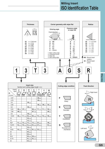
ISO Identification Table Thickness
Corner geometry with wiper flat Entering angle
Radius
Clearance angle on wiper flat
Feed direction 4
02 03 T3 04 05 06 07 09
A 45° D 60° E 75° F 85° P 90° Z - Others
s = 2,38 mm s = 3,18 s = 3,97 s = 4,76 s = 5,56 s = 6,35 s = 7,94 s = 9,52
3
A 3° B 5° C 7° D 15° E 20° F 25° G 30° N 0° P 11° Z - Others
1. Major cutting edge 2. Chamfered corner 3. Wiper flat 4. Side cutting edge
T
Insert size Symbol and cutting edge length
3 2
3 (mm)
A
G
Cutting edge condition
02 04 08 12 16 20 24
S
R Feed direction
Right hand
IC d (mm) 3,97 06 (6,9) 4,76 08 (8,2)
F Sharp
5,0 05 (5,0) 5,56 09 (9,6) 09 (9,7) 03 (3,8) 6,0 06 (6,0) 6,35
06 (6,4) 07 (7,7) 06 (6,35) 11 (11,0) 11 (11,1) 04 (4,3)
7,94
08 (8,0) 07 (7,94) 05 (5,4)
8,0 08 (8,0) 9,525 09 (9,7) 11 (11,6) 09 (9,525) 09 (9,525) 16 (16,5) 16 (16,6) 06 (6,5) 10 10 (10,0)
E Rounded
12 (12,9) 15 (15,5) 12 (12,7) 12 (12,7) 22 (22,0) 08 (8,7)
15,875 16 (16,1) 19 (19,4) 15 (15,875) 15 (15,875) 27 (27,5) 10 (10,9) 16 16 (16,0) 19,05
19 (19,3) 19 (19,05) 19 (19,05) 33 (33,0)
Neutral
T Chamfered
12 12 (12,0) 12,7
0,2 mm 0,4 0,8 1,2 1,6 2,0 2,4
M0 - Round insert (metric) 00 - Round insert (inch)
Insert type
r= r= r= r= r= r= r=
Milling Cutters
1
1
S Rounded and chamfered
Left hand
20 20 (20,0) 25 25 (25,0) 25,4 25 (25,4) 25 (25,4) 31,75 31(31,75) 31(31,75) 32 32 (32,0)
G5