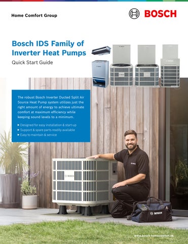
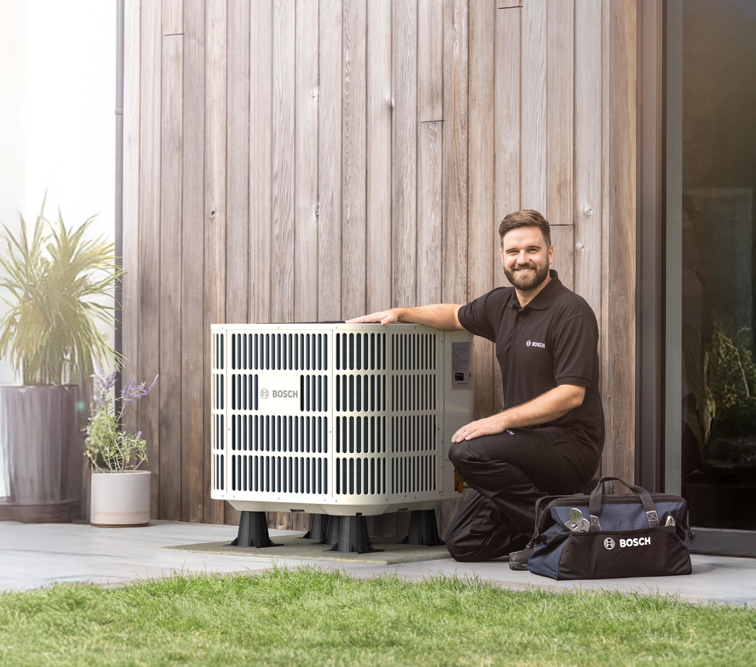
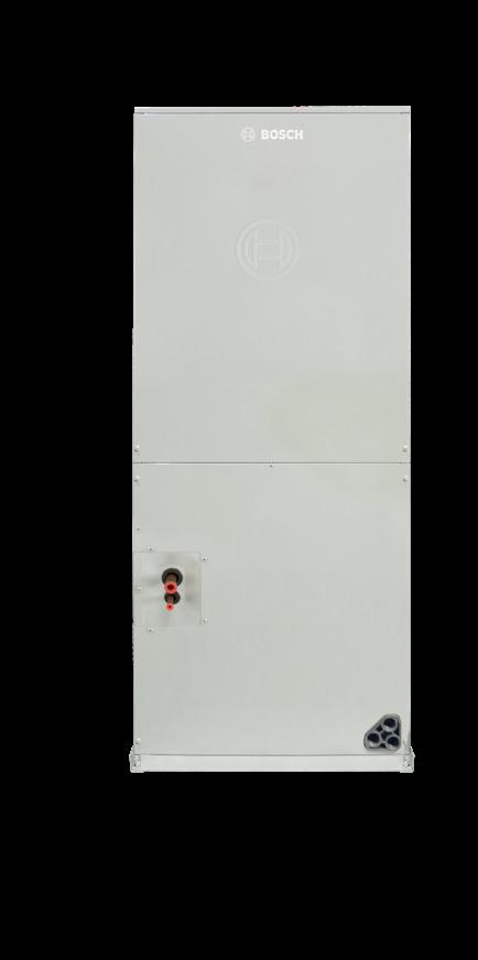
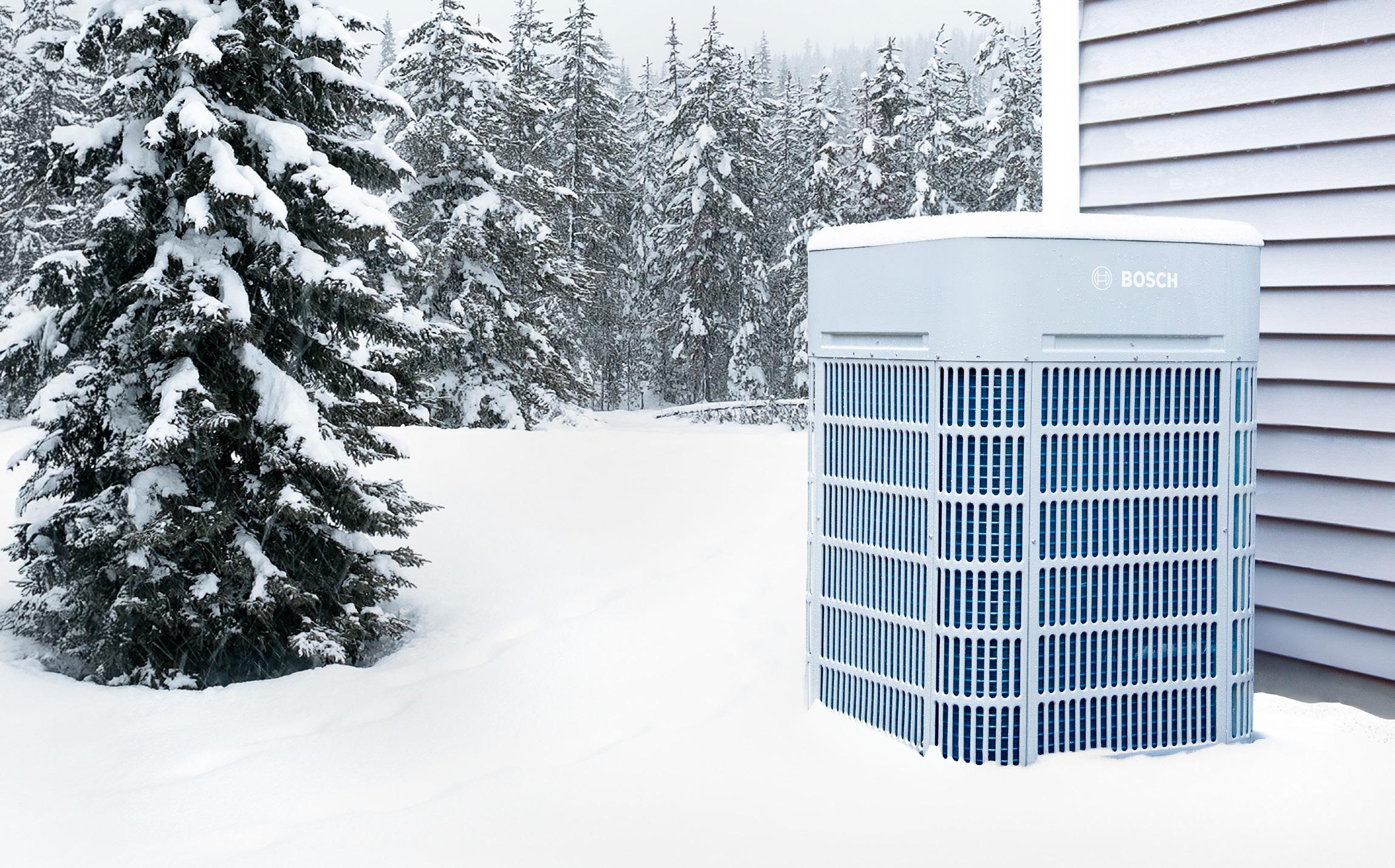
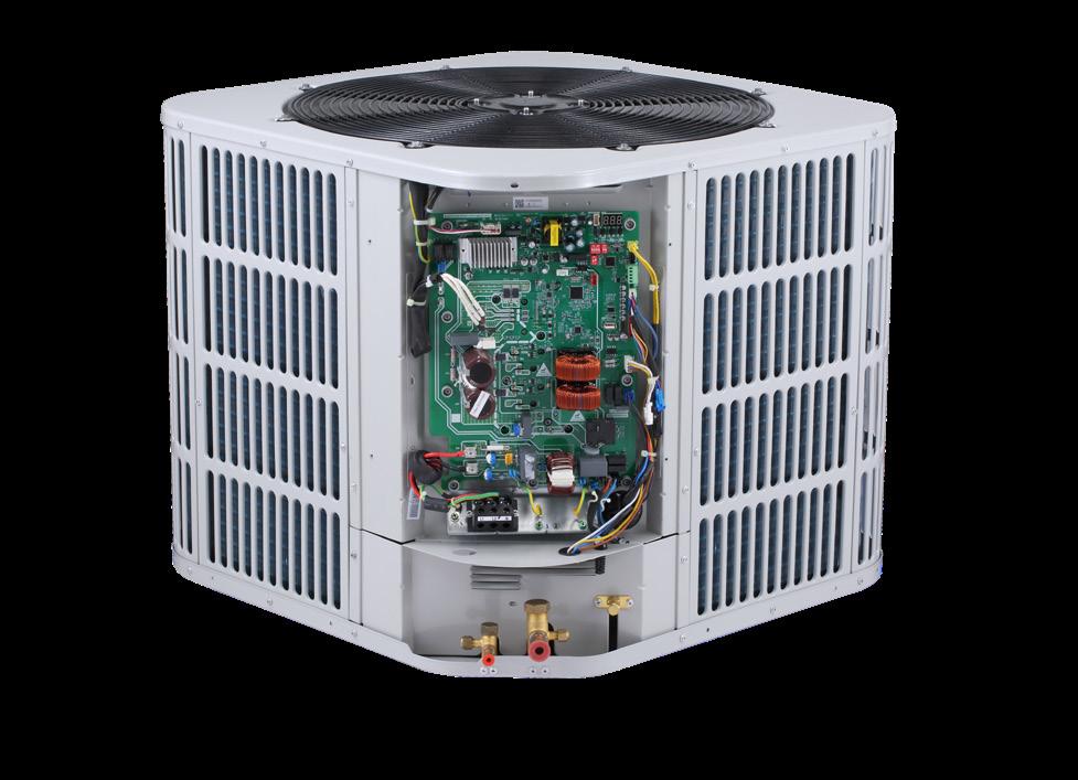
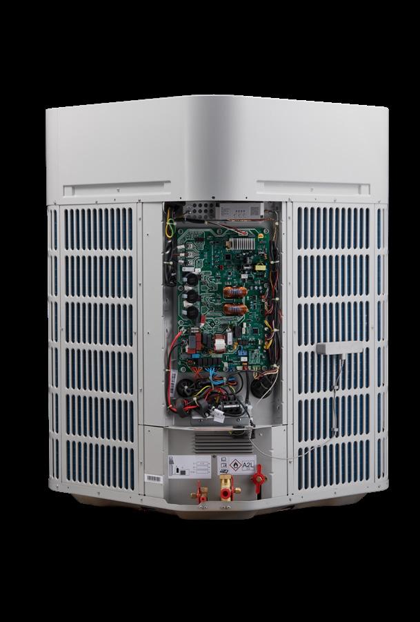
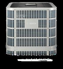
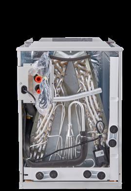
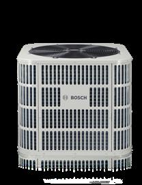
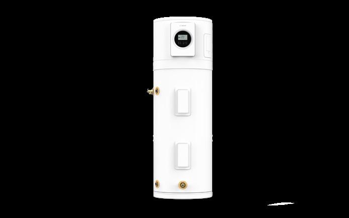
The robust Bosch Inverter Ducted Split Air Source Heat Pump system utilizes just the right amount of energy to achieve ultimate comfort at maximum efficiency while keeping sound levels to a minimum.
▶ Designed for easy installation & start-up
▶ Support & spare parts readily available
▶ Easy to maintain & service
Bosch IDS Family
Smarter Comfort, Greater Efficiency, Every Season!
The Complete Lineup of Bosch IDS Inverter Ducted Split Systems
Give your customers what they want: quiet, reliable, energy-efficient comfort all year long. From entry-level to advanced connected solutions, the Bosch IDS Family delivers options for every home, every climate, and every budget.
Versatile Lineup
Four systems ranging from 15 to 20 SEER2, covering 24K to 60K BTU capacities.
Inverter Technology
Fully modulating compressors use only the energy needed, reducing wear and extending system life.
Quiet Operation
With sound levels as low as 56 dBA, homeowners enjoy peace and comfort.
Cold Climate Ready
IDS Ultra provides heating down to -13°F.
Strong Warranty Protection
10-year residential limited warranty on parts plus coverage for connectivity components on select models.
Smart Connectivity
Premium Connected and Ultra models offer remote monitoring, troubleshooting, and easy warranty registration through the Bosch EasyAir app.
Dual Fuel Solutions
Pair with the Bosch BGH96 Furnace for maximum efficiency and peace of mind in harsh winters.
Installer Friendly
Compact footprint, intuitive controls, in-app installation guides, and easy service access save you time on the job.
Trusted Bosch Engineering
Durable all-aluminum coils, corrosion-resistant cabinets, and Bosch’s rigorous testing standards
IDS Light
Entry-Level Efficiency
▶ Up to 15.2 SEER2 / 8.5 HSPF2 for energy savings
▶ Quiet operation as low as 59 dBA
▶ Compact footprint for easy installation in tight spaces
▶ Compatible with most 24V thermostats
▶ Bosch inverter technology for steady comfort and reduced energy use
▶ Dual fuel capable with Bosch BGH96 Gas Furnace
▶ All-aluminum coils for durability and reduced leak risk
▶ Backed by a 10-year residential limited warranty
IDS Plus
Enhanced Performance at a Great Value
▶ Up to 18 SEER2 / 8.5 HSPF2 for affordable efficiency
▶ Ultra-quiet operation as low as 56 dBA
▶ Two-stage ECM blower motor for better humidity control
▶ Fully modulating inverter drive for precise comfort
▶ ENERGY STAR® rated for rebates and incentives
▶ Simple, installer-friendly design with onboard diagnostics
▶ Dual fuel pairing for optimal comfort in colder climates
▶ 10-year parts warranty for peace of mind
IDS Premium Connected
Smart, High-Efficiency Comfort
▶ Up to 20 SEER2 / 9.5 HSPF2 — Bosch’s highest efficiency
▶ Bosch EasyAir app for remote monitoring and troubleshooting
▶ Wireless connectivity for fast setup and diagnostics
▶ Sound levels as low as 60 dBA
▶ Variable-capacity inverter compressor adapts between 35% and 138% output
▶ Qualifies for maximum rebates and incentives
▶ Dual fuel ready with Bosch BGH96 Gas Furnace
▶ 10-year limited warranty plus connectivity component coverage
IDS Ultra
Cold Climate Champion
▶ Cold climate performance: 100% heating capacity at 5°F, reliable to -13°F
▶ Up to 19 SEER2 / 10.0 HSPF2 for maximum year-round comfort
▶ DOE Cold Climate Heat Pump Challenge approved
▶ Enhanced Vapor Injection (EVI) compressor for powerful low-temp heating
▶ Bosch EasyAir app for remote monitoring and fast troubleshooting
▶ Quiet operation with sound isolating mounts and blade technology
▶ Dual fuel capability for added peace of mind in extreme cold
▶ 10-year parts warranty plus EasyAir connectivity coverage
Engineered for Performance. Built
for Contractors. Trusted by Homeowners.
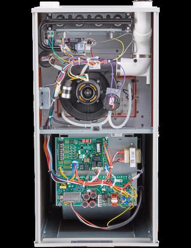
Every component of the Bosch IDS Family is designed with precision engineering to deliver reliable comfort, simplified installation, and long-lasting efficiency.
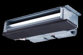
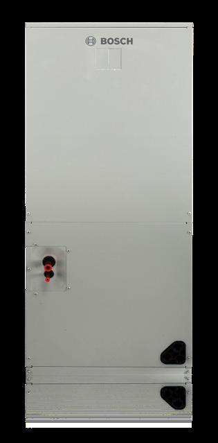
The Bosch Inverter Ducted Split (IDS) Family sets a new standard for heating and cooling. From high - efficiency condensers to space - saving air handlers, every system is engineered for comfort, quiet performance, and easy serviceability.
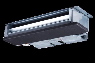
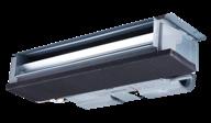
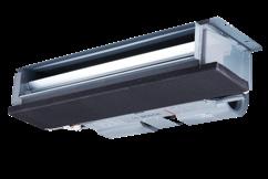
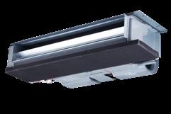
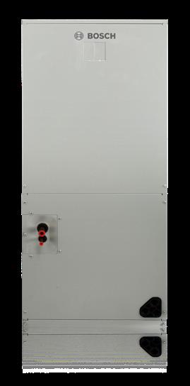
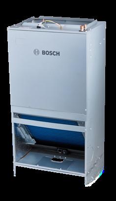
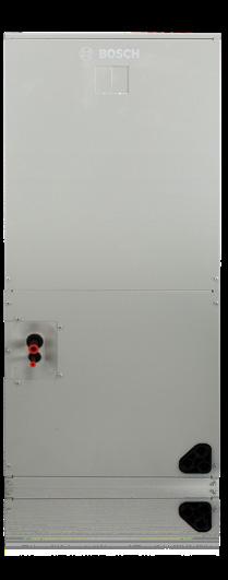
With durable all-aluminum coils, precision inverter compressors, and smart control boards, Bosch delivers lasting reliability and efficiency. Multiple air handler options, traditional, wall- mounted, or ceiling - mounted, make it easy to meet any home’s needs.
Installer-friendly features like intuitive controls, onboard diagnostics, and in -app support help you save time, reduce callbacks, and deliver the comfort homeowners expect.
IDS Components Features & Benefits
Intelligent Control Features
Automatically adjust system output to maintain consistent comfort and humidity control year-round.
High-Efficiency Inverter Compressor
Modulates in precise increments for maximum efficiency and energy savings.
Smart Connectivity (Premium Connected & Ultra)
Wireless setup, remote monitoring, troubleshooting, and warranty registration via the Bosch EasyAir app.
PSC / ECM / Constant Torque Motors
Efficient, reliable blower options to match system performance needs.
Electric Heat Capability
Easily accommodate electric heat strips for additional comfort on demand.
All-Aluminum Coil
Superior heat transfer and durability with reduced risk of refrigerant leaks.
Advanced ECM Blower Motor (Ultra)
Four-stage motor provides enhanced comfort, superior humidity control, and energy savings.
Control Board Pocket
Protected location shields the control board from moisture, extending its lifespan.
Integrated Drain Pan
Corrosion-resistant, sloped design reduces standing water and ensures long-term reliability.
Filter Rack
Factory-installed for easy serviceability and improved indoor air quality.
Corrosion-Resistant Cabinets
Rugged galvanized steel tested for durability and long-lasting performance.
The Complete & Highly Efficient Dual Fuel Heating and Cooling
System For Your Home
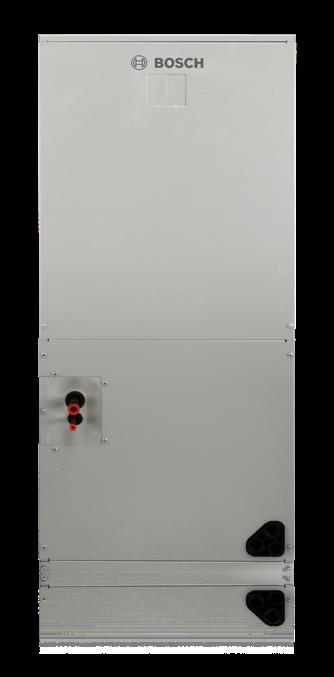
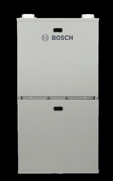
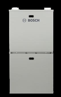
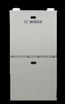
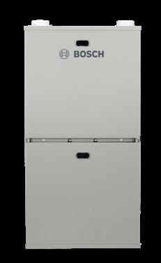
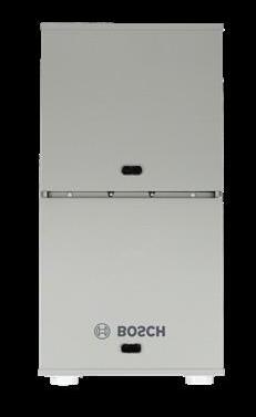
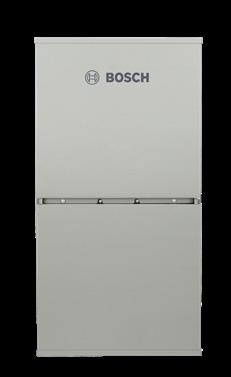
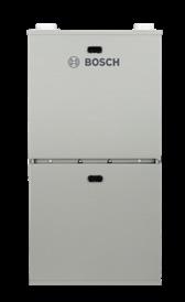
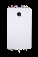
Bosch BGH96 96% Furnace*
The BGH96 Gas Furnace offers up to 96% efficiency, a two-stage gas valve, and a multi-speed blower and a blower built with constant air flow technology. This ENERGY STAR rated furnace offers premium comfort and energy savings, it is the perfect solution to efficiently heat your home. Compatible with R-454B heat pump systems.
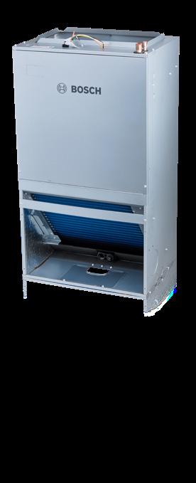
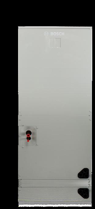
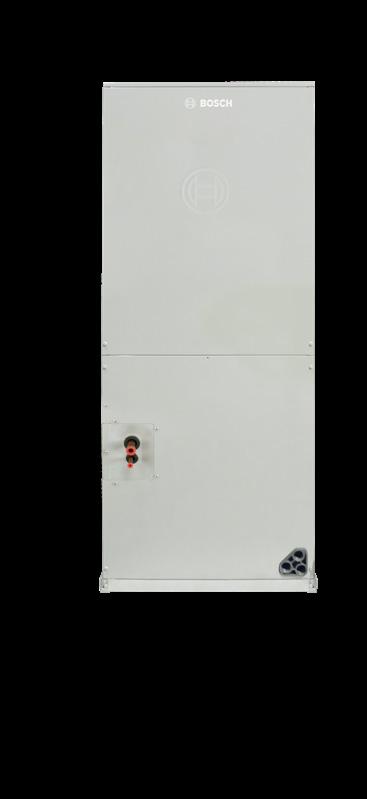
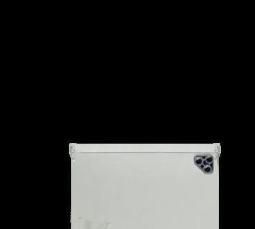
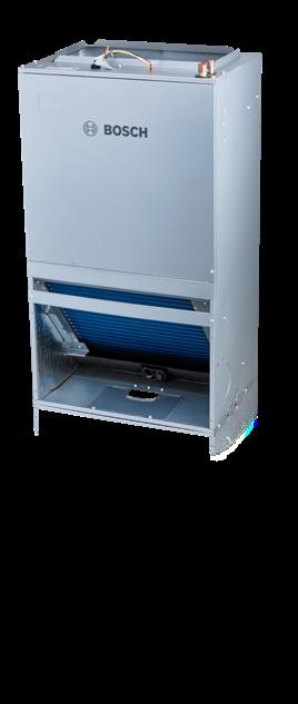
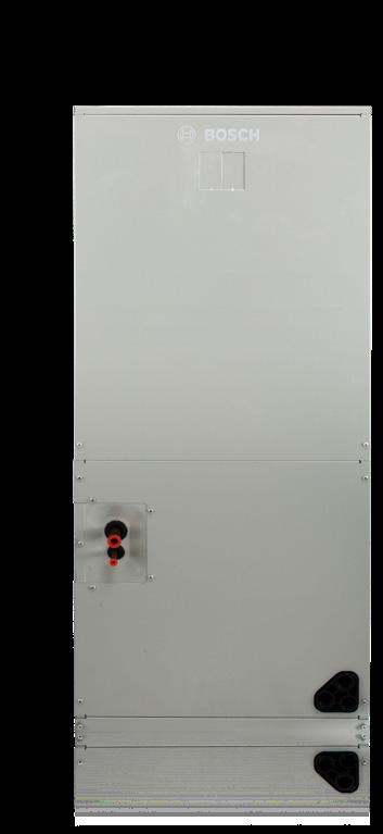
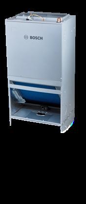
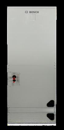
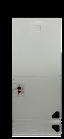
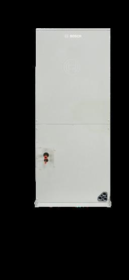
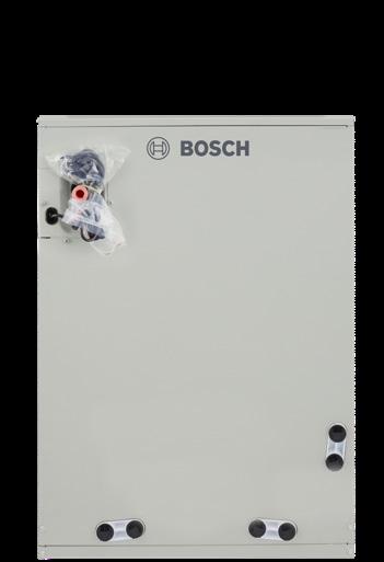
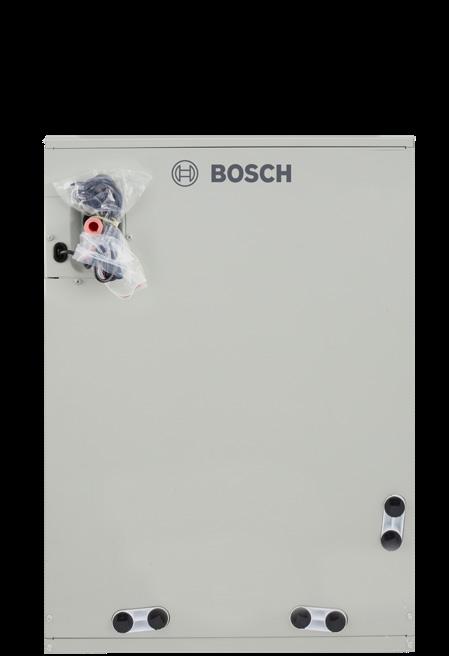
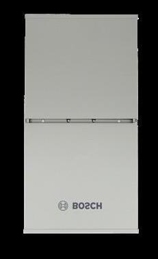
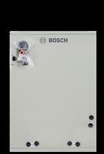
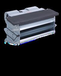
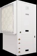
Bosch BMAC Cased Coil*
The Inverter Ducted Split Cased Coil, when paired with a Bosch Furnace and IDS outdoor condensing section, delivers some of the best comfort levels and efficiency on the market today. Bosch offers a complete range of cased coils to fit your needs.
C
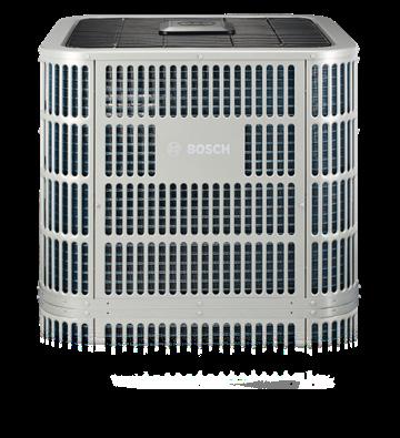
LGWP IDS
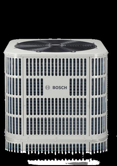
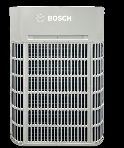
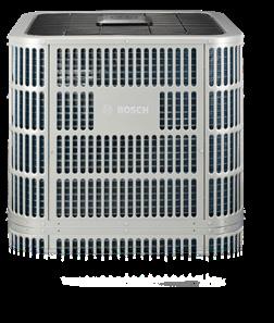
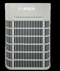
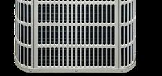
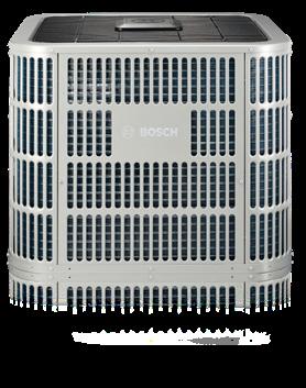
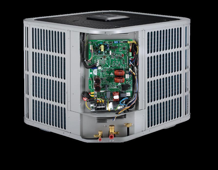
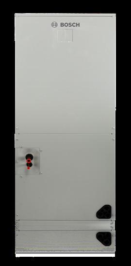
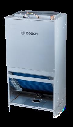
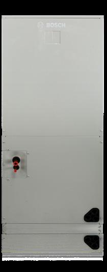
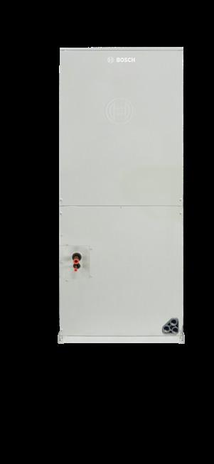
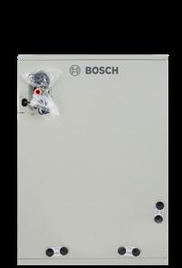
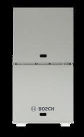
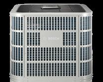
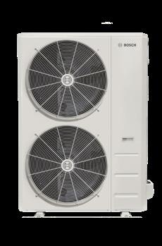
Outdoor unit*
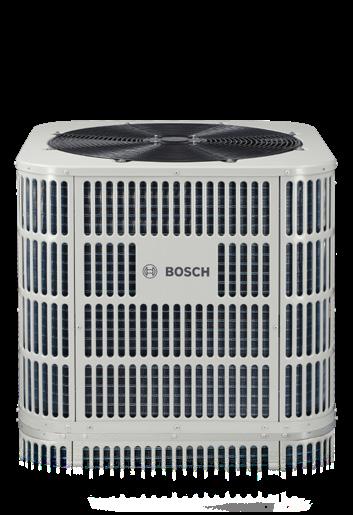
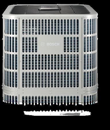
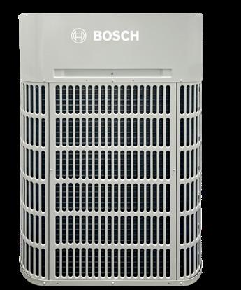
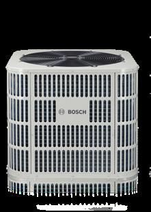
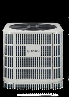
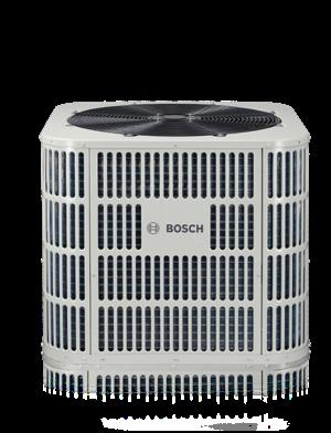
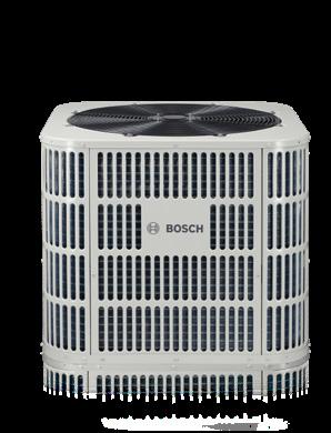
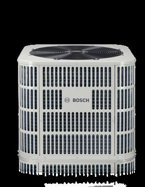
The robust Bosch Inverter Ducted Split Air Source Heat Pump system utilizes just the right amount of energy to achieve ultimate comfort and maximum efficiency while keeping sound levels to a minimum. Choose from one of three options
D
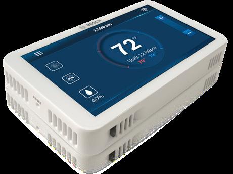
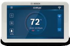
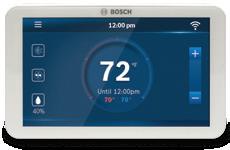
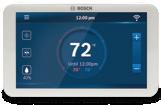
Bosch BCC110 Wi-fi Thermostat*
The BCC110 is a sleek, internet-connected thermostat that offers easy all-in-one control for your heating and cooling systems. It can be controlled using the Bosch EasyAir app and is compatible with most 24VAC HVAC equipment on the market.
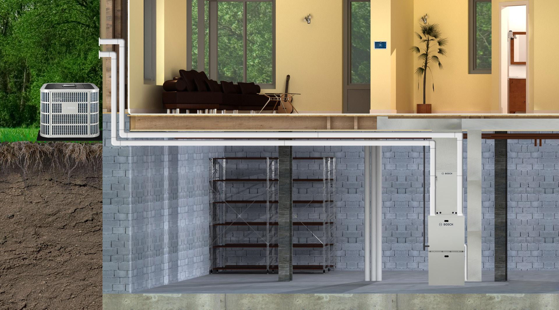
Bosch IDS Dual Fuel Provides Optimal Comfort Every Season!
An Ideal Solution to Maximize Comfort & Efficiency
Bosch offers a complete dual fuel heating and cooling system for your home. Dual fuel systems are the ideal solution to maximize comfort and efficiency. In the summer, the Bosch IDS efficiently cools and dehumidifies your home. In the colder months, the system senses when it is more economical for the heat pump to shut off and the Bosch BGH96 gas furnace to take over. Installing a Bosch matched dual fuel system is the best choice to optimize both savings and comfort.
Bosch Dependable and Multi-Positional Cased Coils
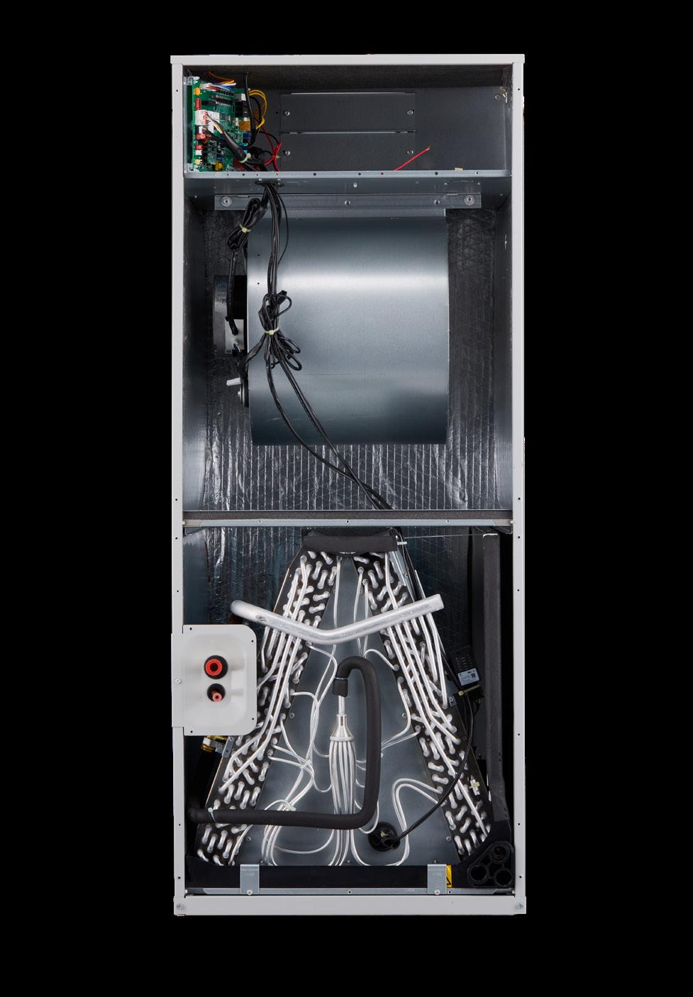
The Inverter Ducted Split Evaporator Coil, when paired with a furnace along with an IDS outdoor condensing section, will deliver some of the best comfort levels and efficiency on the market today. Bosch offers a complete range of cased evaporator coils to fit your needs. Have peace of mind knowing that all Bosch cased coil models include a 10-year parts residential warranty.§
Cased Evaporator Coil
The cased evaporator coils include easy-to-clean foil-back insulation which helps to ensure against energy loss through the cabinet as well as keeping the unit quiet. Bosch offers a complete range of 10 evaporator coil models from 2 through 5 ton sizes, in all orientations including upflow, downflow and horizontal to fit all duct sizes and meet your needs. Bosch cased coils can be easily installed for retrofit or new contruction applications using the simple slide-out feature. The cased evaporator coils are constructed from all-aluminum fins with aluminum tubing to help prevent formicary corrosion while maintaining high heat transfer efficiency thereby increasing longevity and cost savings.
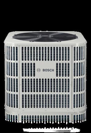
Choose Your Heat Pump Different Options & Price Points
u First 15-SEER Inverter on the market
u Inverter system at a price point you’ll love!
u Robust design
u Small footprint
u Quiet sound levels
u Compatible with most 24V thermostat
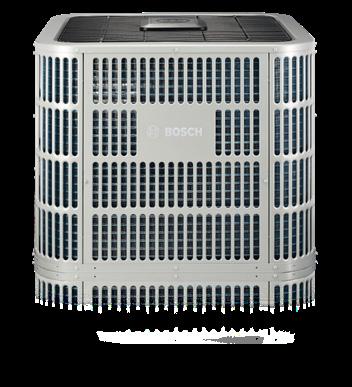
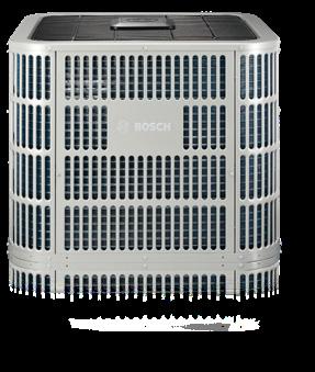
u premium 20-plus SEER energy efficiency
u Features wireless connectivity
u Compatible with Bosch EasyAir app
u Robust design
u Small footprint
u Quiet sound levels
u Compatible with most 24V thermostat
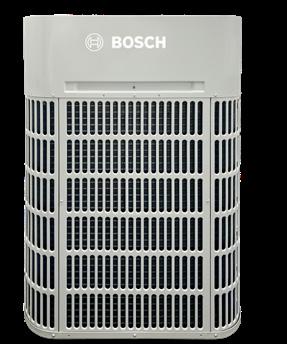
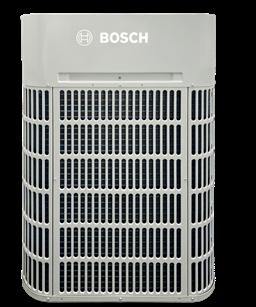
u Cold Climate Heat Pump
u 100% heating capacity down to 5°F
u DOE Challenge approved
u Gateway communication to Cloud
u Robust Design
u Small footprint
u Quiet sound levels
u Compatible with most 24V thermostat
8733965435
8733965436 BGH96M100D5C 8733965437
BGH96M120D5C 8733965438
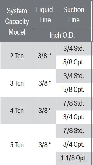
Line Sets and Charging
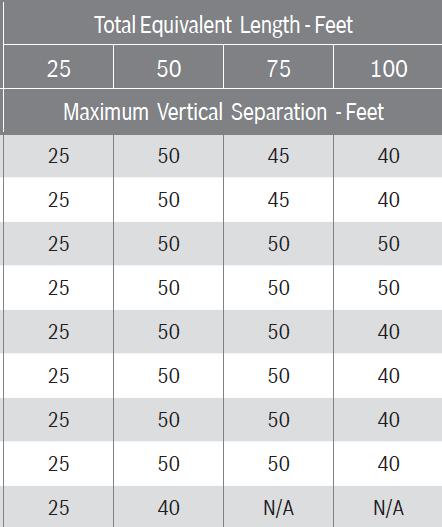
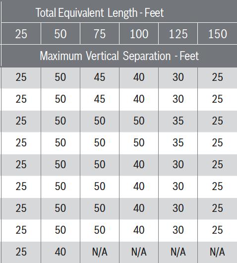
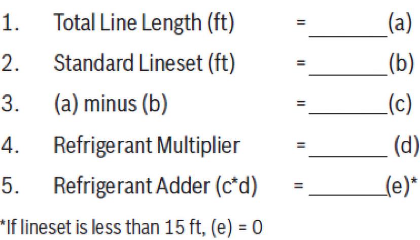
The Bosch condensers come factory pre-charged (R-454B) for 25’ of standard size line set. For the BOV*20, up to 150’ of line set is allowed with a maximum of 50’ lift (refer to Figure 2.1). For the BOVA15 and BOVB18, up to 100’ of line set is allowed with a maximum of 50’ lift (refer to figure 2.2). Any Application with line set length of more than 25’ would require an additional 0.6 oz/ft for each additional foot of line set (refer to Figure 2.2), this can be done by one of two methods: (1) Charge by Weight, (2) Charge by Subcooling.
(1) Charge by Weight
Can be used at any time and is the recommended way to charge an IDS system (especially for initial installs). This method can be used when power is not available to the equipment site or when operating conditions are not in range to verify the charge based on subcooling. It is recommend to verify charge and adjust as necessary by subcooling. (Refer to Figure 2.4 for subcooling and superheat requirements.)
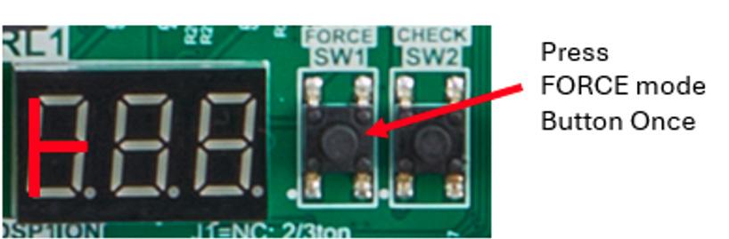
(2) Adjusting charge based on Subcooling & Superheating (AC Mode)
Outside temperature must be between 55° and 120°F and indoor temperature must be between 70° and 80°F to charge by subcooling. After starting the system in cooling mode, short press “FORCE” button (see Figure 2.3), “ ” symbol Appears, and operate the system for a minimum of 20 minutes. (Refer to Figure 2.4 for subcooling and superheat requirements.)
Check the superheat and select correct subcooling according to superheat, refer to "Final Subcooling table". It is recommended to keep the superheat at 10-18°F if a third party indoor unit is used.
Figure 2.3
Figure 2.2
*From 15 ft to 25 ft N/A: Application not recommended
Figure 2.1
Figure 2.4
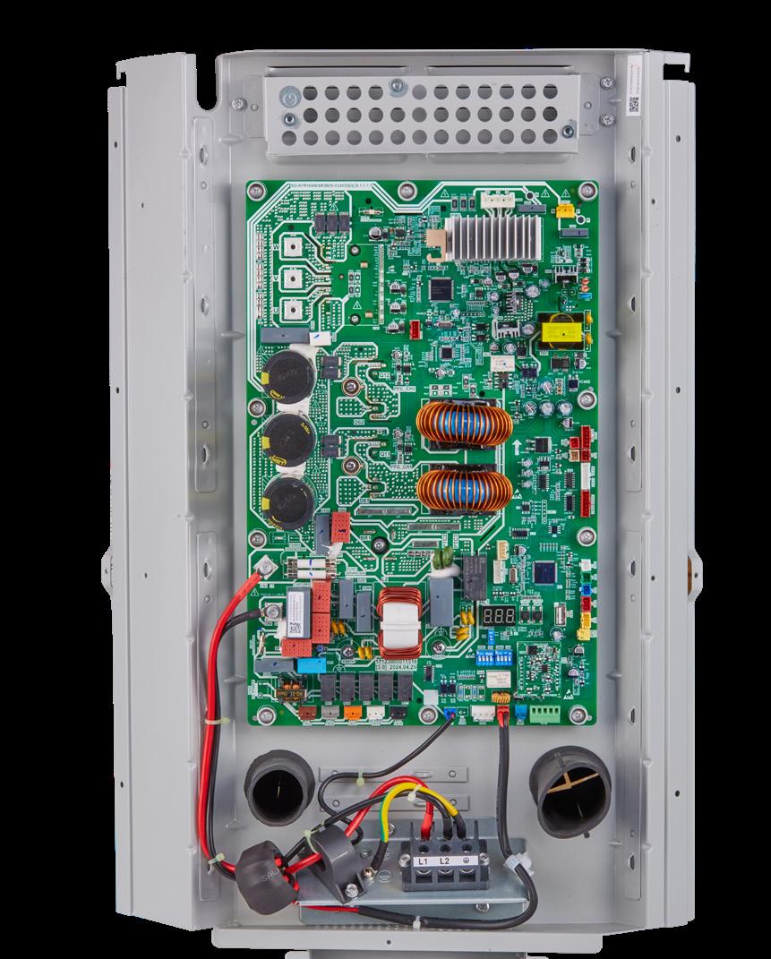
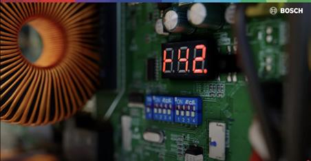
Onboard Parameter Check & Diagnostics
1. Press “Check” button to index through parameters.
2. After first pressing on the “Check” button, it will display the sequence, and after 1 second it will display the value of the parameter.
3. After 20 seconds on same parameter, display will revert back to normal status.
4. If a system protection is active, first digit will display “status code.”
Check Mode Button
Manual/Force Defrost
1. System must have a call for heat and have been operating for a minimum of 8 minutes.
2. Press “FORCE” button on inverter board for 6 seconds to begin forced defrost.
3. Wait Approximately 40 seconds for defrost to initiate.
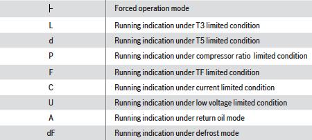
4. Once defrost initiates the display will indicate “dF”.
5. Defrost test will terminate automatically after which the display will indicate running speed.
6. Repeat steps after 5 minutes if second test is required.
System Protection Codes Figure 4.5
Check Mode Button
Force Button
CODE
FAULT DESCRIPTION
Atl Ambient Temperature Limited (T4)
b1 Temperature sensor fault in Indoor Unit (T1)-ULTRA UNIT ONLY
b2 Temperature sensor fault in Indoor Unit (T2)
b3 R454B refrigerant Sensor hardware fault in Indoor Unit
b4 R454B refrigerant sensor communication (wiring) fault in Indoor Unit
b5 Communication fault between Indoor unit and Outdoor unit
b6 Power consumption sensor fault in indoor unit
b7 R454B refrigerant leakage protection in indoor unit
b8 R454B refrigerant sensor over service life in indoor unit
c3 The coil sensor is seated fault in cooling (T3)
E41 Temperature sensor fault (T3)
E42 Temperature sensor fault (T3L)
E43 Temperature sensor fault (T4)
E44 Temperature sensor fault (T5)
E45 Temperature sensor fault (Th)-PREMIUM & LIGHT UNIT ONLY
E46 Temperature sensor fault (T6A)-ULTRA UNIT ONLY
E47 Temperature sensor fault (T6B)-ULTRA UNIT ONLY
E48 Temperature sensor fault (T7)-ULTRA UNIT ONLY
E49 Baseplate heating fault-ULTRA UNIT ONLY
E51 Outdoor unit high/low input voltage
E52 Outdoor unit high/low DC bus voltage protection
E7 Compressor discharge sensor is seated fault (T5)
E81 EEVA coil fault
E82 EEVC coil fault-ULTRA UNIT ONLY
EA Control program does not match drive program in outdoor unit
F1 High pressure switch fault (HPS)
F2* 5 Times (P2) protection in 100 minutes, system lockout
F4 Pressure transducer fault (PT)-LIGHT UNIT ONLY
F41 High pressure sensor fault-ULTRA & PREMIUM UNIT ONLY
F42 Low pressure sensor fault-ULTRA & PREMIUM UNIT ONLY
H01 Drive chip communication fault in outdoor unit
H04 Power consumption sensor communication fault in outdoor unit-ULTRA UNIT ONLY)
H14 Power consumption sensor fault in outdoor unit-ULTRA UNIT ONLY
J00-JCF Compressor drive fault
n00-nCF Outdoor fan motor driver fault
P0 Compressor IPM temperature protection
P1 High pressure switch protection (HPS)
P11 High pressure protection in cooling/heating (Pc)
P21 Low pressure protection in cooling/heating (Pe)
P31 Outdoor init input over current protection
P32 Compressor over current protection
P4 High compressor discharge temperature protection (T5)
P5 Condenser coil temperature protection in cooling (T3)
Pb1 Hyper-Link (M1 M2) over current protection -ULTRA UNIT ONLY
PH Low discharge superheat protection
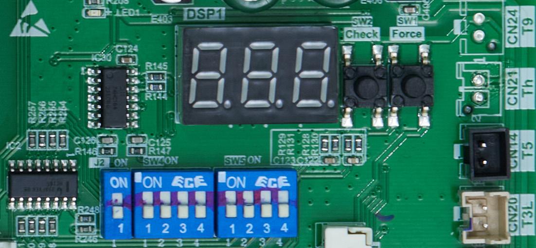
Control Board Display
Figure 4.1
Figure 4.4
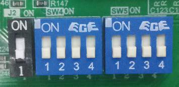
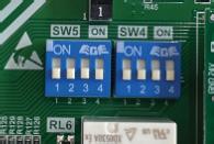
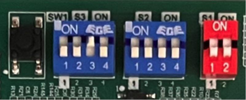
Control Board & Dip Switch Functions
In most scenarios, it is recommended to keep all outdoor unit board dip switch positions in their manufacturer default positions. There are some specific scenarios when it makes sense to change dip switch settings.
Dip Switch SW4
SW4-1 and SW4-2 are not used and should remain in the factory default position at all times. SW4-3 and SW4-4 give you coil temperature and modulation control.
SW4-3 Function
Default is OFF position (enabled), allows for coil/ condenser target temperature to drift +/- 4°F based on previous hour of operation in an attempt to optimize run time. If dip switch is changed to ON, software requires a “hard” target for coil temperature and does not drift to optimize runtime. Reason to change from default: In zoning Applications but only as needed as a result of customer expectations and/ or performance.
SW4-4 Function
Default is OFF position, system uses the default target coil temperatures. If dip switch is changed to ON, reduces target coil temperature by 4°F in cooling and increases target coil temperature by 4°F in heating. Reason to change from default: Recommended to be used only as-needed as a result of customer expectations and/or performance (i.e. not getting enough capacity, or not dehumidifying well enough).
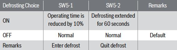
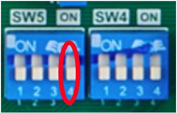
SW5-1 Function
Default is OFF position, uses default defrost operating time (maximum of 8 minutes). If dip switch is changed to ON, the default operating time before a unit goes into defrost is reduced by 10%. Reason to change from default: Can be used in colder climates to have the unit go into defrost more often.
Dip Switch SW5
Demand Defrost Adjustments
SW5-2 Function
Default is OFF position, uses default defrost operating time (maximum of 8 minutes). If change dip switch to ON, default defrost time is increased by 1 minute. Reason to change from default: Can be used in colder climates, where it make take more time than usual to defrost the outdoor coil.
J2 Function
Default is ON, which leaves the compressor capacity at default (3 or 5 ton depending on the model). Regardless of if the matching air handler is 2 ton or 3 ton (when paired with the 3 ton condenser), or matching air handler is 4 ton or 5 ton (when paired with 5 ton condenser), the J2 jumper can be left at default position. The compressor will ramp to required coil temperature regardless of paired air handler size. Reason to change from default: If you want (or need) to minimize maximum condenser capacity from 3 to 2 tons (3 ton condenser model) OR 5 to 4 tons (5 ton condenser model).
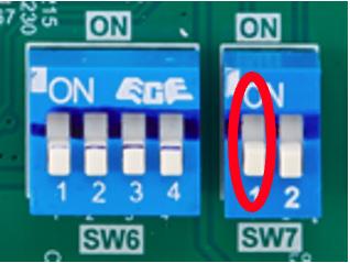
Communicating Dipswitches (SW7-1 & SW5-4)
Factory Default SW7-1 & SW5-4 is “ON” and must be turned “OFF” for non-communicating 24VAC connections.
IDS Light & Plus (BOVA15)
17 System Operation and Troubleshooting
17.1
Control Logic Description
Control Board & Dip Switch Adjustments
17 System Operation and Troubleshooting
• The variable speed system adopts the same 24VAC control as any by the unit's pressure transducer. To ensure stable and adequate capacity,
Control Logic Description
heating operation. The target pressure can automatically adjust based on compressor operation so optimal capacity can be achieved. Target pressure can be manually adjusted (SW4) to achieve improved dehumidification and
17.2 Sensors (Thermistors/Pressure Transducer)
• T3 = Outdoor Coil Temperature (Table 26)
◦ High/Low temperature protection
◦ Outdoor fan control (cooling mode)
SW4-1 ON Unused OFF Must be set at "OFF" position
Description
SW4-1 ON Unused OFF Must be set at "OFF" position
SW4-2 ON Unused OFF Must be set at "OFF" position
SW4-2 ON Unused OFF Must be set at "OFF" position
SW4-3 ON Adaptive Capacity Output Disable OFF Adaptive Capacity Output Enable*
• Defrost Termination Settings (SW5) offers different defrost termination options for enhanced defrost for different geographical and outdoor conditions.
SW4-3 ON Adaptive Capacity Output Disable OFF Adaptive Capacity Output Enable*
• Defrost Termination Settings (SW5) offers different defrost termination options for enhanced defrost for different geographical and outdoor conditions.
SW4-4 ON Accelerated Cooling/Heating OFF Normal Cooling/Heating*
Table 21
SW4-4 ON Accelerated Cooling/Heating OFF Normal Cooling/Heating*
Table 21
*Factory Default
*Factory Default
•
• Adaptive capacity function is a "self-learning function" which allows a range of target coil temperatures to adapt for better unit operation and reduced short cycling.
17.2 Sensors (Thermistors/Pressure Transducer)
◦ Defrost control (heating mode)
• T3 = Outdoor Coil Temperature (Table 26)
• T4 = Ambient Temperature (Table 26)
◦ High/Low temperature protection
◦ Operating condition permission
◦ Outdoor fan control (cooling mode)
◦ Defrosting condition permission
◦ Defrost control (heating mode)
◦ Outdoor fan control (heating mode)
• T4 = Ambient Temperature (Table 26)
• T5 = Compressor Discharge Temperature (Table 27)
◦ Electronic Expansion Valve (EEV) control (heating mode only)
• Pressure transducer
◦ High pressure protection (heating mode)
◦ Compressor frequency control
◦ Low pressure protection (cooling mode)
◦ Electronic Expansion Valve (EEV) control (heating mode only)
◦ High pressure protection (heating mode)
◦ Low pressure protection (cooling mode)
17.3 Pressure Equalizer Valve (PEV)
Used to balance the pressure in the system before compressor start up.
17.3 Pressure Equalizer Valve (PEV)
Used to balance the pressure in the system before compressor start up.
17.4 Defrost Description
17.4 Defrost Description
17.6 Reversing Valve Operation
• The Demand Defrost Control (DDC) monitors the ODU coil temperature using thermistor (T3). A second thermistor (T4) monitors outdoor ambient temperature. Based on these parameters, as well as accumulative run time and high pressure, the DDC calculates proper initiation of defrost.
Installation and Operating Instructions
• Any one of the below three conditions is required to enter defrost:
17.6 Reversing Valve Operation
• Reversing valve energizes during heat mode and de-energizes in cool mode. The input voltage of reversing valve is 220V.
• Reversing valve energizes during heat mode and de-energizes in cool mode. The input voltage of reversing valve is 220V.
• Any one of the below three conditions is required to enter defrost: 1. The calculated temperature difference between the outdoor temperature (T4) and the coil temperature (T3) is called Delta T. After Delta T is achieved and continues for 3 minutes.
1. The calculated temperature difference between the outdoor temperature (T4) and the coil temperature (T3) is called Delta T. After Delta T is achieved and continues for 3 minutes.
◦ T4 ≥ 39°F, Delta T = 18°F
◦ T4 ≥ 39°F, Delta T = 18°F
◦ T4 ≥ 30°F, Delta T = 16°F
• Adaptive capacity function is a "self-learning function" which allows a range of target coil temperatures to adapt for better unit operation and reduced short cycling.
During a heat call on first time operation the unit will run about 1 minute in cooling to build up pressure for the reversing valve to change.
◦ T4 ≥ 30°F, Delta T = 16°F
◦ T4 ≥ 19°F, Delta T = 14°F
◦ T4 ≥ 19°F, Delta T = 14°F
During a heat call on first time operation the unit will run about 1 minute in cooling to build up pressure for the reversing valve to change.
17.7
◦ When T4 < 19°F, T3 < 9°F, accumulative compressor run time ≥ 80 minutes.
Protection Functions
◦ When T4 < 19°F, T3 < 9°F, accumulative compressor run time ≥ 80 minutes.
• Accelerated cooling/heating function changes the initial target coil temperature to provide "enhanced comfort" by increasing unit capacity.
• Accelerated cooling/heating function changes the initial target coil temperature to provide "enhanced comfort" by increasing unit capacity.
• Manual Defrost:
17.7
Protection Functions
• Outdoor coil temperature protection (T3)
• Outdoor coil temperature protection (T3)
2. After “Minimum Run Time” (MRT) is achieved. MRT is based on outdoor ambient temperature (T4), for example:
i. If T3 ≥ 147.2°F, compressor is de-energized.
2. After “Minimum Run Time” (MRT) is achieved. MRT is based on outdoor ambient temperature (T4), for example:
◦ MRT is 4 hours when: T4 < 23°F
i. If T3 ≥ 147.2°F, compressor is de-energized. ii. If T3 < 133°F, compressor is energized.
ii. If T3 < 133°F, compressor is energized.
◦ MRT is 4 hours when: T4 < 23°F
• Ambient temperature protection (T4)
◦ MRT is 2 hours when: 23°F ≤ T4 < 40°F
◦ MRT is 2 hours when: 23°F ≤ T4 < 40°F
• Ambient temperature protection (T4)
i. If 40°F ≤ T4 < 120°F, unit can operate in cooling.
◦ MRT is 50 minutes when: Last defrost cycle was at least 8 minutes.
ii. If 3°F ≤ T4 < 86°F, unit can operate in heating.
◦ MRT is 50 minutes when: Last defrost cycle was at least 8 minutes.
i. If 40°F ≤ T4 < 120°F, unit can operate in cooling. ii. If 3°F ≤ T4 < 86°F, unit can operate in heating. iii. If T4 < 1.4°F, heat pump will provide 24V control to indoor unit energizing electric heat (if installed). See
3. After the high pressure saturation temperature drops below 82°F for 20 minutes when 14F <= T4 < 29F.
3. After the high pressure saturation temperature drops below 82°F for 20 minutes when 14F <= T4 < 29F.
iii. If T4 < 1.4°F, heat pump will provide 24V control to indoor unit energizing electric heat (if installed).
• Defrost will terminate once outdoor coil temperature (T3) reaches 64°F for a period of 1 minute or defrost time has exceeded 8 minutes.
• Defrost will terminate once outdoor coil temperature (T3) reaches 64°F for a period of 1 minute or defrost time has exceeded 8 minutes.
• Discharge Temperature (DT)
(T5) i. If DT > 230°F during cooling or heating mode, the compressor will stop. ii. If DT < 185°F during cooling or heating mode, the compressor will restart.
IDS Premium (BOVA20)
Control Board & Dip Switch Adjustments
18.1 Control Logic Description
• The variable speed system adopts the same 24VAC control as any conventional heat pump.
18.1 Control Logic Description
• The variable speed system adopts the same 24VAC control as any conventional heat pump.
• The compressor’s speed is controlled based on coil pressures monitored by the unit's pressure transducer. To ensure stable and adequate capacity, the compressor speed will modulate relative to evaporator pressure during cooling operation and relative to condensing pressure during heating operation. The target pressure can automatically adjust based on compressor operation so optimal capacity can be achieved. Target pressure can be manually adjusted (SW4) to achieve improved dehumidification and capacity demands.
18.2 Sensors (Thermistors/Pressure Transducer)
• T4 = Ambient Temperature (Table 25)
• T3 = Outdoor Coil Temperature (Table 25)
◦ Operating condition permission
◦ High/Low temperature protection
◦ Defrosting condition permission
◦ Outdoor fan control (cooling mode)
◦ Outdoor fan control (heating mode)
◦ Defrost control (heating mode)
• T5 = Compressor Discharge Temperature (Table 26)
• The compressor’s speed is controlled based on coil pressures monitored by the unit's pressure transducer. To ensure stable and adequate capacity, the compressor speed will modulate relative to evaporator pressure during cooling operation and relative to condensing pressure during heating operation. The target pressure can automatically adjust based on compressor operation so optimal capacity can be achieved. Target pressure can be manually adjusted (SW4) to achieve improved dehumidification and capacity demands.
SW4-1 ON Unused OFF Must be set at "OFF" position
• Defrost will terminate once outdoor coil temperature (T3) reaches 64°F for a period of 1 minute or defrost time has exceeded 8 minutes.
• Defrost will terminate once outdoor coil temperature (T3) reaches 64°F for a period of 1 minute or defrost time has exceeded 8 minutes.
• Defrost Termination Settings (SW5) offers different defrost termination options for enhanced defrost for different geographical and outdoor conditions.
• Defrost Termination Settings (SW5) offers different defrost termination options for enhanced defrost for different geographical and outdoor conditions.
Table 20 *Factory Default
• Adaptive capacity function is a "self-learning function" which allows a range of target coil temperatures to adapt for better unit operation and reduced short cycling.
◦ High pressure protection (cooling mode)
◦ Control board overheat protection
◦ Low pressure protection (heating mode)
• Pc = Condensing Pressure Transducer
◦ Compressor frequency control
• Pe = Evaporating Pressure Transducer
◦ High pressure protection (cooling mode)
◦ Compressor frequency control
◦ Low pressure protection (heating mode)
◦ Electronic Expansion Valve (EEV) control (heating mode only)
• Pe = Evaporating Pressure Transducer
◦ High pressure protection (heating mode)
◦ Compressor frequency control
◦ Low pressure protection (cooling mode)
◦ Electronic Expansion Valve (EEV) control (heating mode only)
◦ High pressure protection (heating mode)
18.3 Pressure Equalizer Valve (PEV)
◦ Low pressure protection (cooling mode)
Used to balance the pressure in the system before compressor start up.
18.3 Pressure Equalizer Valve (PEV)
18.4 Defrost Description
Used to balance the pressure in the system before compressor start up.
18.4 Defrost Description
• The Demand Defrost Control (DDC) monitors the ODU coil temperature using thermistor (T3). A second thermistor (T4) monitors outdoor ambient temperature. Based on these parameters, as well as accumulative run time and high pressure, the DDC calculates proper initiation of defrost.
• The Demand Defrost Control (DDC) monitors the ODU coil temperature using thermistor (T3). A second thermistor (T4) monitors outdoor ambient temperature. Based on these parameters, as well as accumulative run time and high pressure, the DDC calculates proper initiation of defrost.
• Any one of the below three conditions is required to enter defrost:
• Any one of the below three conditions is required to enter defrost:
1. The calculated temperature difference between the outdoor temperature (T4) and the coil temperature (T3) is called Delta T. After Delta T is achieved and continues for 3 minutes.
1. The calculated temperature difference between the outdoor temperature (T4) and the coil temperature (T3) is called Delta T. After Delta T is achieved and continues for 3 minutes.
◦ T4 ≥ 39°F, Delta T = 18°F
◦ T4 ≥ 39°F, Delta T = 18°F
Installation and Operating Instructions
◦ T4 ≥ 30°F, Delta T = 16°F
◦ T4 ≥ 30°F, Delta T = 16°F
◦ T4 ≥ 19°F, Delta T = 14°F
◦ T4 ≥ 19°F, Delta T = 14°F
• CCH operation de-energizes:
◦ When T4 < 19°F, T3 < 9°F, accumulative compressor run time ≥ 80 minutes.
◦ When T4 < 19°F, T3 < 9°F, accumulative compressor run time ≥ 80 minutes.
Installation and Operating Instructions
1. Compressor discharge temperature T5 ≥ 60.8°F.
2. Compressor start running.
• CCH operation de-energizes:
2. After “Minimum Run Time” (MRT) is achieved. MRT is based on outdoor ambient temperature (T4), for example:
2. After “Minimum Run Time” (MRT) is achieved. MRT is based on outdoor ambient temperature (T4), for example:
◦ MRT is 4 hours when: T4 < 23°F
◦ MRT is 4 hours when: T4 < 23°F
1. Compressor discharge temperature T5 ≥ 60.8°F.
18.6 Reversing Valve Operation
◦ MRT is 2 hours when: 23°F ≤ T4 < 40°F
2. Compressor start running.
◦ MRT is 2 hours when: 23°F ≤ T4 < 40°F
• Reversing valve energizes during heat mode and de-energizes in cool mode. The input voltage of reversing valve is 220V.
18.6 Reversing Valve Operation
◦ MRT is 50 minutes when: Last defrost cycle was at least 8 minutes
◦ MRT is 50 minutes when: Last defrost cycle was at least 8 minutes
• Reversing valve energizes during heat mode and de-energizes in cool mode. The input voltage of reversing valve is 220V.
3. After the high pressure saturation temperature drops below 82°F for 20 minutes when 14F <= T4 < 29F.
3. After the high pressure saturation temperature drops below 82°F for 20 minutes when 14F <= T4 < 29F.
• Adaptive capacity function is a "self-learning function" which allows a range of target coil temperatures to adapt for better unit operation and reduced short cycling.
• Accelerated cooling/heating function changes the initial target coil temperature to provide "enhanced comfort" by increasing unit capacity.
• Accelerated cooling/heating function changes the initial target coil temperature to provide "enhanced comfort" by increasing unit capacity.
During a heat call on first time operation the unit will run about 1 minute in cooling to build up pressure for reversing valve to change.
During a heat call on first time operation the unit will run about 1 minute in cooling to build up pressure for reversing valve to change.
18.7 Protection Functions
• Outdoor coil temperature protection (T3)
18.7 Protection Functions
• Outdoor coil temperature protection (T3)
i. If T3 ≥ 150°F, compressor is de-energized.
ii. If T3 < 133°F, compressor is energized.
i. If T3 ≥ 150°F, compressor is de-energized.
• Ambient temperature protection (T4)
ii. If T3 < 133°F, compressor is energized.
• Ambient temperature protection (T4)
i. If 15°F ≤ T4 < 125°F, unit can operate in cooling.
ii. If ‒4°F ≤ T4 < 86°F, unit can operate in heating.
i. If 15°F ≤ T4 < 125°F, unit can operate in cooling.
ii. If ‒4°F ≤ T4 < 86°F, unit can operate in heating.
iii. If T4 < -4°F, heat pump will provide 24V control to indoor unit energizing electric heat (if installed).
iii. If T4 < -4°F, heat pump will provide 24V control to indoor unit energizing electric heat (if installed). See BOVA20 Product Specification for
See BOVA20 Product Specification for extended performance data.
• Discharge Temperature (DT)
(T5)
• Discharge Temperature (DT) protection (T5) i. If DT > 230°F during cooling or heating mode, the compressor will stop. ii. If
i. If DT > 230°F during cooling or heating mode, the compressor will stop. ii. If DT < 185°F during cooling or heating mode, the compressor will
SW4
Figure 70
T3
IDS ULTRA (BOVA19)
Control Board & Dip Switch Adjustments
18.1 Control Logic Description
T4 = Ambient Temperature (Table 26)
◦ High/Low temperature protection
◦ Operating condition permission
◦ Outdoor fan control (cooling mode)
◦ Defrosting condition permission
◦ Defrost control (heating mode)
◦ Outdoor fan control (heating mode)
• T4 = Ambient Temperature (Table 26)
• T5 = Compressor Discharge Temperature (Table 27)
• The variable speed system adopts the same 24VAC control as any conventional heat pump.
18.1 Control Logic Description
• The variable speed system adopts the same 24VAC control as any conventional heat pump.
• The compressor’s speed is controlled based on coil pressures monitored by the unit's pressure transducer. To ensure stable and adequate capacity, the compressor speed will modulate relative to evaporator pressure during cooling operation and relative to condensing pressure during heating operation. The target pressure can automatically adjust based on compressor operation so optimal capacity can be achieved. Target pressure can be manually adjusted (SW4) to achieve improved dehumidification and capacity demands.
• The compressor’s speed is controlled based on coil pressures monitored by the unit's pressure transducer. To ensure stable and adequate capacity, the compressor speed will modulate relative to evaporator pressure during cooling operation and relative to condensing pressure during heating operation. The target pressure can automatically adjust based on compressor operation so optimal capacity can be achieved. Target pressure can be manually adjusted (SW4) to achieve improved dehumidification and capacity demands.
Installation Instructions
• Th = Compressor Return Temperature (Table 26)
• T6A = Temperature at inlet of plate heat exchanger Electronic Expansion Valve Control (EEVC) (ODU/heating mode only) (Table 26)
T3L = Liquid Line Temperature (Table 26)
• T6B = Temperature at outlet of plate heat exchanger Electronic Expansion Valve Control (EEVC) (ODU/heating mode only) (Table 26)
• T6A = Temperature at inlet of plate heat exchanger Electronic Expansion Valve Control (EEVC) (ODU/heating mode only) (Table 26)
• T6B = Temperature at outlet of plate heat exchanger Electronic Expansion Valve Control (EEVC) (ODU/heating mode only) (Table 26)
• T7 = Liquid Service Valve Temperature Accurate subcooling measurements (Table 27)
• Pc = Condensing Pressure Transducer
◦ Compressor frequency control
• T7 = Liquid Service Valve Temperature Accurate subcooling measurements (Table 27)
• Pc = Condensing Pressure Transducer
◦ High pressure protection (cooling mode)
◦ Low pressure protection (heating mode)
◦ Compressor frequency control
◦ High pressure protection (cooling mode)
• Pe = Evaporating Pressure Transducer
◦ Low pressure protection (heating mode)
◦ Compressor frequency control
• Pe = Evaporating Pressure Transducer
◦ Electronic Expansion Valve (EEVA) control (heating mode only)
◦ Compressor frequency control
◦ High pressure protection (heating mode)
Description
Switch Description
Installation Instructions
SW4-1 ON Unused OFF* Must be set at "OFF" position
SW4-1 ON Unused OFF* Must be set at "OFF" position
3. After the high pressure saturation temperature drops below 82°F for 20 minutes and 14°F≤T4<29°F.
SW4-2 ON Accelerated cooling/heating 1 OFF*
• Defrost will terminate once outdoor coil temperature (T3) reaches 64°F for a period of 1 minute or defrost time has exceeded 8 minutes.
3. After the high pressure saturation temperature drops below 82°F for 20 minutes and 14°F≤T4<29°F.
SW4-2 ON Accelerated cooling/heating 1 OFF* Normal cooling/heating
Accelerated cooling/heating 2
SW4-3
SW4-3 ON Accelerated cooling/heating 2 OFF* Normal cooling/heating
Normal cooling/heating
• Defrost will terminate once outdoor coil temperature (T3) reaches 64°F for a period of 1 minute or defrost time has exceeded 8 minutes.
• Defrost Termination Settings (SW5) offers different defrost termination options for enhanced defrost for different geographical and outdoor conditions.
• Defrost Termination Settings (SW5) offers different defrost termination options for enhanced defrost for different geographical and outdoor conditions.
Adaptive capacity output enabled
Table 21
Table 21
*Factory Default
*Factory Default
◦ Low pressure protection (cooling mode)
◦ Electronic Expansion Valve (EEVA) control (heating mode only)
◦ High pressure protection (heating mode)
◦ Low pressure protection (cooling mode)
◦ Outdoor unit current sensor -measures total outdoor unit power consumption
◦ Outdoor unit current sensor -measures total outdoor unit power consumption
18.3 Pressure Equalizer Valve (PEV/SV5)
Used to balance the pressure in the system before compressor start up.
18.3 Pressure Equalizer Valve (PEV/SV5)
Used to balance the pressure in the system before compressor start up.
18.4 Defrost Description
18.4 Defrost Description
• The Demand Defrost Control (DDC) monitors the ODU coil temperature using thermistor (T3). A second thermistor (T4) monitors outdoor ambient temperature. Based on these parameters, as well as accumulative run time and high pressure, the DDC calculates proper initiation of defrost.
• CCH operation energizes:
• The Demand Defrost Control (DDC) monitors the ODU coil temperature using thermistor (T3). A second thermistor (T4) monitors outdoor ambient temperature. Based on these parameters, as well as accumulative run time and high pressure, the DDC calculates proper initiation of defrost.
1. First time line voltage is applied and compressor discharge temperature T5 < 53.6°F.
• Any one of the below three conditions is required to enter defrost:
• CCH operation energizes:
1. First time line voltage is applied and compressor discharge temperature T5 < 53.6°F.
• Any one of the below three conditions is required to enter defrost: 1. The calculated temperature difference between the outdoor temperature (T4) and the coil temperature (T3) is called Delta T. Defrost is initiated after Delta T is achieved and continues for 3 minutes.
2. Compressor stops running for 3 hours (outdoor ambient temperature T4 < 41°F OR compressor discharge temperature T5 < 53.6°F).
1. The calculated temperature difference between the outdoor temperature (T4) and the coil temperature (T3) is called Delta T. Defrost is initiated after Delta T is achieved and continues for 3 minutes.
• CCH operation de-energizes:
◦ T4 ≥ 39°F, Delta T = 18°F
2. Compressor stops running for 3 hours (outdoor ambient temperature T4 < 41°F OR compressor discharge temperature T5 < 53.6°F).
1. Compressor discharge temperature T5 ≥ 60.8°F.
◦ T4 ≥ 39°F, Delta T = 18°F
2. Compressor start running.
◦ T4 ≥ 30°F, Delta T = 16°F
• CCH operation de-energizes:
◦ T4 ≥ 30°F, Delta T = 16°F
◦ T4 ≥ 19°F, Delta T = 14°F
1. Compressor discharge temperature T5 ≥ 60.8°F.
◦ T4 ≥ 19°F, Delta T = 14°F
18.6 Reversing Valve Operation
2. Compressor start running.
◦ When T4 < 19°F, T3 < 9°F, accumulated compressor run time ≥ 95 minutes.
◦ When T4 < 19°F, T3 < 9°F, accumulated compressor run time ≥ 95 minutes.
Reversing valve energizes during heat mode and de-energizes in cool mode.
18.6 Reversing Valve Operation
• Adaptive capacity function is a "self-learning function" which allows a range of target coil temperatures to adapt for better unit operation and reduced short cycling.
• Adaptive capacity function is a "self-learning function" which allows a range of target coil temperatures to adapt for better unit operation and reduced short cycling.
2. After “Minimum Run Time” (MRT) is achieved. MRT is based on outdoor ambient temperature (T4), for example:
2. After “Minimum Run Time” (MRT) is achieved. MRT is based on outdoor ambient temperature (T4), for example:
Reversing valve energizes during heat mode and de-energizes in cool mode.
◦ MRT is 4 hours when: T4 < 23°F
◦ MRT is 4 hours when: T4 < 23°F
◦ MRT is 2 hours when: 23°F ≤ T4 < 42°F
◦ MRT is 2 hours when: 23°F ≤ T4 < 42°F
• Accelerated cooling/heating function changes the initial target coil temperature to provide "enhanced comfort" by increasing unit capacity.
• Manual Defrost:
• Manual Defrost:
• Accelerated cooling/heating function changes the initial target coil temperature to provide "enhanced comfort" by increasing unit capacity.
During a heat call on first time operation the unit will run about 1 minute in cooling to build up pressure for reversing valve to change.
◦ MRT is 50 minutes when the previous defrost duration was at least 8 minutes
◦ MRT is 50 minutes when the previous defrost duration was at least 8 minutes
During a heat call on first time operation the unit will run about 1 minute in cooling to build up pressure for reversing valve to change.
18.7 Basepan Heater Operation
18.7 Basepan Heater Operation
When the ambient temperature is low, the baseplate heater will be automatically turned on to prevent the baseplate from blocked by ice.
When the ambient temperature is low, the baseplate heater will be automatically turned on to prevent the baseplate from blocked by ice.
• Baseplate heater operation energizes:
• Baseplate heater operation energizes:
◦ Outdoor ambient temperature T4<35.6°F in heating model.
◦ Outdoor ambient temperature T4<35.6°F in heating model.
• Baseplate heater operation de-energizes:
• Baseplate heater operation de-energizes:
◦ Outdoor ambient temperature T4≥39.2 °F last more than 1 minute.
◦ Outdoor ambient temperature T4≥39.2 °F last more than 1 minute.
◦ Switch to cooling mode
◦ Switch to cooling mode
18.8 Protection Functions
18.8 Protection Functions
• Outdoor coil temperature protection (T3)
• Outdoor coil temperature protection (T3)
i. If T3 > 150.8°F, compressor is de-energized.
i. If T3 > 150.8°F, compressor is de-energized. ii. If T3 < 132.8°F, compressor is energized.
ii. If T3 < 132.8°F, compressor is energized.
• Ambient temperature protection (T4)
• Ambient temperature protection (T4)
i. If 14°F ≤ T4 < 125°F, unit can operate in cooling.
Figure 72
Figure 73
Bosch IDS Heat Pump Ultra Series Condensing Unit - BTC 762003305 C (10.2024)
Figure 72
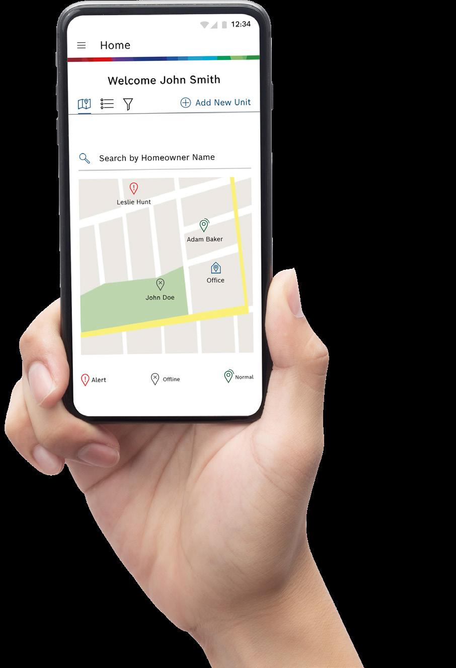
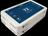
Bosch EasyAir App
Troubleshooting
Made Easy!
The Bosch EasyAir App is your one-stop shop for troubleshooting the IDS Premium Connected. With just a few swipes on your phone, you can easily access information about installation, warranty registration, and how to monitor the unit remotely.
Remote Monitoring & Troubleshooting
Monitor the heat pump’s health and visualize real time alerts remotely. View fault codes, live check point values and calculate superheat and subcool values that will help in troubleshooting faults quickly.
Get Notified on System Faults
Receive alerts on your phone right away about unit errors, warnings, and other important updates.
Manage Your Technicians
As the owner of the company or an office admin that dispatches technicians, you can add installers/ technicians to your company profile and manage which homeowner units they can access.
Warranty Registration
Quickly and efficiently register products for warranty at the click of a button in the EasyAir App.
Connected Features
Bosch EasyAir Mobile App
The Bosch Premium Connected and Ultra condenser features wireless connectivity and allows the contractor to access information about warranty registration, installation, and troubleshooting via the Bosch EasyAir App.
To utilize all the connected features of the Bosch ODU ensure the following:
1. The antenna has been mounted as instructed.
2. The Bosch EasyAir App has been downloaded on your smartphone.
3. The condenser has been added to the Bosch EasyAir App.
4. The condenser is linked to the homeowner and access to monitor the condenser remotely has been granted.
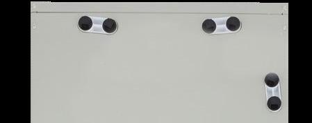
The antenna is used to transmit data to the cloud and will have the strongest signal strength mounted furthest away from a wall or building.
the
For the strongest signal mount the antenna on the side furthest from a wall on the left or right side of the unit.
Downloading the Bosch EasyAir App
1. Download the Bosch EasyAir App on your smartphone by searching for it in Google Play Store (for Android devices) or App Store (for iPhone). Alternatively, you can scan this QR code with your phone’s camera.
2. Open the Bosch EasyAir App and create a profile.
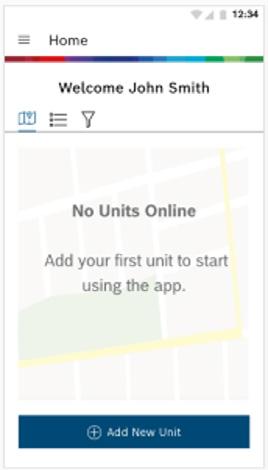
Adding the Condenser to the Bosch EasyAir App
Open the Bosch EasyAir App, From the ‘Home’ Screen click on the “Add New Unit” button and follow instructions on the App.
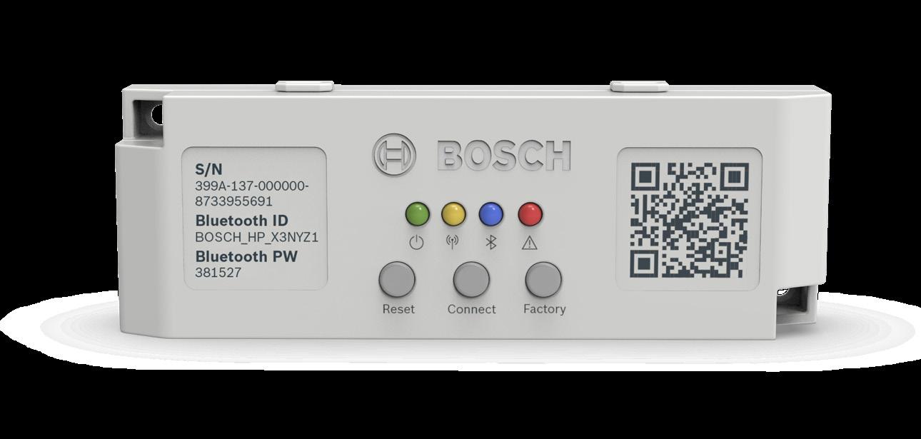
Connecting to the Bosch Premium Connected (BOVB20) Condenser
1. Ensure the unit is powered on.
2. Once the unit is powered on, wait until the gateway has a solid green and amber LED.
3. Launch the Bosch EasyAir App and connect to the unit via Bluetooth.
4. Access the Unit Dashboard to install, troubleshoot and register warranty more efficiently.
Scan QR with Smartphone to Download App
Mount
antenna on the 3rd Louver from the bottom of the unit.
Communicating Wiring Diagrams
Non-Communicating Wiring Diagrams
IDS Light Non-Communicating
Communicating w/Furnace
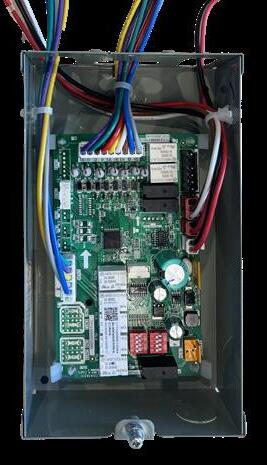
IDS with Furnace or MBX Modular Blower
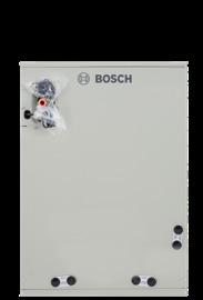
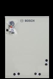
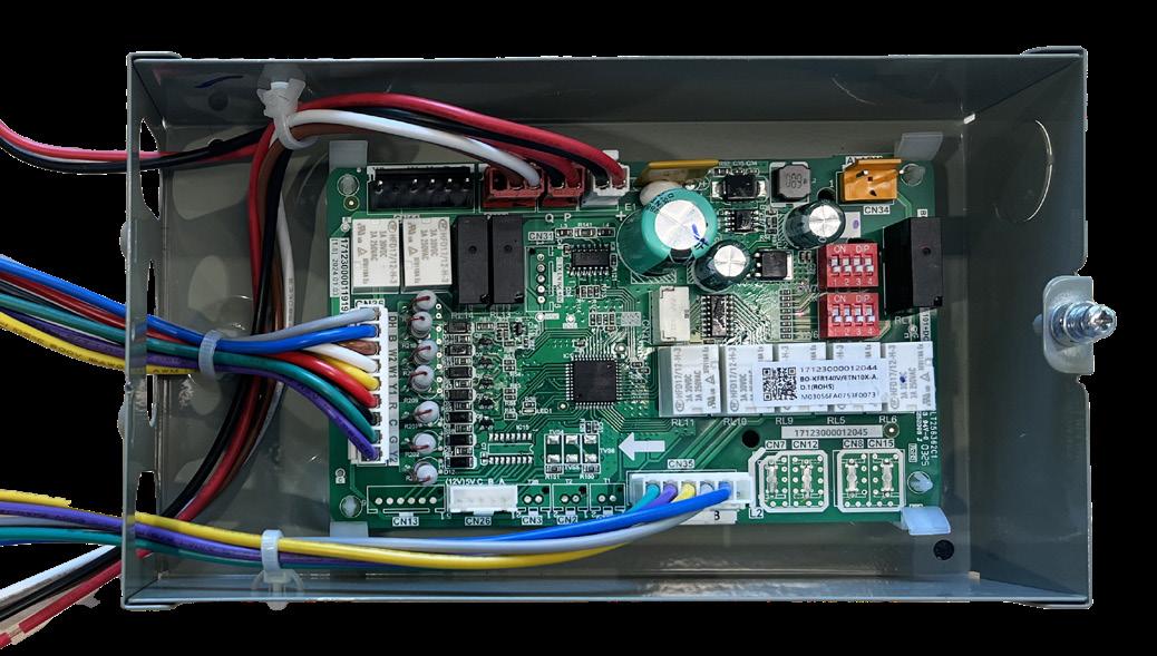
Wiring and Control Logic (A2L Box)
BOVA20
BOVA15
BOVA20
Non-Communicating w/ Furnace
IDS with Furnace or MBX Modular Blower
Wiring and Control Logic (A2L Box)
Bosch BGH96 Gas Furnace
Pair the Bosch BGH96 Gas Furnace with the Bosch IDS Family for the ultimate dual fuel solution. In the warmer months, the IDS inverter heat pump delivers whisper- quiet, energy - efficient cooling and dehumidification. When temperatures drop, the BGH96 seamlessly takes over, providing powerful and efficient heating, ensuring homeowners enjoy year- round comfort without compromise.
Airflow Adjustment
Equipped with an EON ECM circulator blower motor which provides ease in adjusting blower speeds
Blower speeds should be adjusted by the installer to match the installation requirements to provide the correct heating temperature rise and the correct cooling CFM.
Adaptor Box Wiring Logic
To ODU
To Thermostat
3rd Party Furnace or RevB Bosch
To Furnace
Cased Coil A2L Sensor (R454B Sensor)
Bosch IDS
Cooling Today, Heating Tomorrow with Just One Wire
A Heat Pump System That Works Like A/C Right Out of the Box
Used to installing straight cooling systems? Out of the box, the Bosch Inverter Ducted Split (IDS) system operates as a cooling-only unit. That means you can install this heat pump just like any standard A/C system, using only two wires. When the homeowner is ready to turn on the heat, you can enable heating simply by energizing the O/B wire, adding a heat pump thermostat, and 1-2 additional low voltage conductors.
How This Setup Works:
Installs like A/C: Ships in coolingonly mode for familiar installs
Heat is built-in: Just one wire needed to unlock it
No special thermostat required: Compatible with OEM and standard Heat Pump thermostats (e.g., Bosch BCC110) as well as 1 heat 1 cool non-communicating thermostats
Perfect for hot regions with mild winters
Electric heat option available: Connect W1/W2 if using Bosch heat strip kits
Futureproofs your install: Add heating later without changing equipment
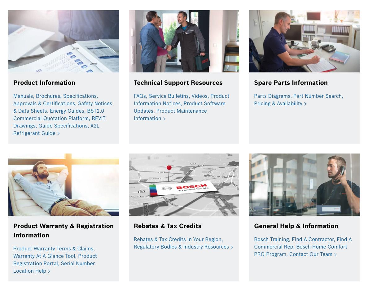
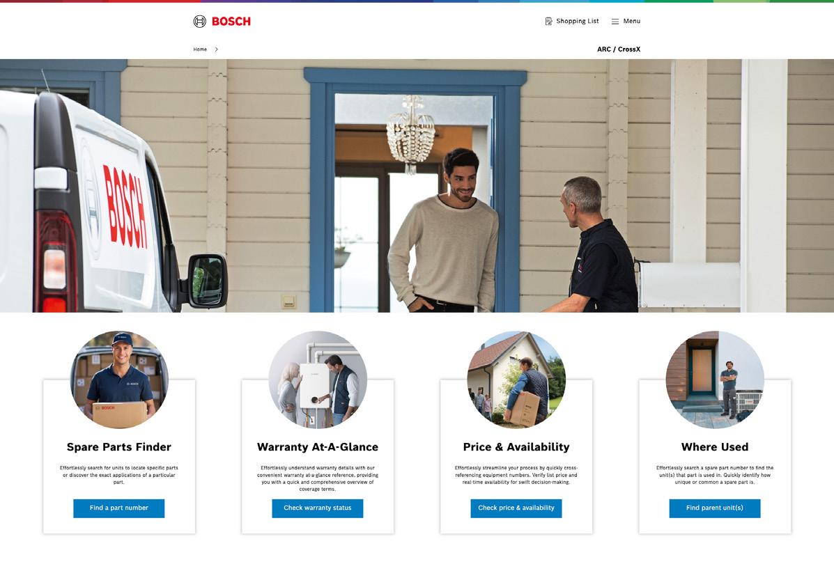
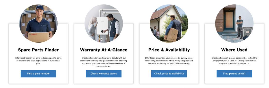
Service & Support Resource
You have arrived at your customer’s location to work on their Bosch equipment. Forgot what that error code means? Where is the temperature sensor?
scheduled maintenance is required? Where is the installation and service manual?
Spare Parts
Finder
Where Used
Spare Parts
Finder
Search equipment by product series along with model number, material number, and serial number. Warranty At-A-Glance F
Search for your part and then click on the part number to see quantity on hand, location, and status.
Enter a part number to find out what parent unit that component is used in.
S
Built for Pros Powered by Bosch
Grow Your Business with Exclusive Tools, Rewards & Support from Bosch.
Bosch is proud to offer contractors a powerful partnership through the Home Comfort PRO Program. Designed to help you grow, manage, and streamline your HVAC business, this FREE program gives you access to a world of benefits; marketing support, lead generation tools, product rewards, and more. Whether you’re just getting started or looking to take your business to the next level, Bosch is here to help you succeed. Join now and get rewarded for doing what you already do best.
By choosing Bosch, you represent one of the largest HVAC brands in the market with over 100 years of industry expertise. Join our team of Professional dealers to gain access to rewards, exclusive sales and marketing tools, technical support, and more.
Earn Points for Every Product Registration
Redeem for Bosch gear, apparel, tools and gift cards!
Access the Bosch Partner Portal
Register products, track rewards, manage your business, and more—on the go.
Seamless Onboarding & Team Management
Easily set up your company profile, invite employees, and assign roles, all from one platform.
Get Found by New Customers
Qualify for Bosch's Installer Locator and Lead Management Tool.
Enjoy Extended Warranty & Priority Support
Platinum PROs earn a 1-year extended parts warranty on every registered install.
Join the Growth Rally Program
Hit your targets and watch your points multiply.
Join the Bosch Home Comfort Program Today!
Bosch Marketing Collateral
Promote your business with downloadable assets and product images.
Track Tier Status & Business Performance
Silver, Gold, and Platinum levels with increasing rewards and visibility.
We invent sustainable heating, cooling and well-being solutions – for a smarter and better life.
About Bosch
Bosch Home Comfort Group in North America
Bosch Home Comfort Group is a leading source of high quality water heating and comfort systems. The company offers gas tankless, electric whole house and point-of-use water heaters, Bosch and Buderus floor-standing and wall mounted boilers, Bosch and FHP geothermal, water-source and air-source systems as well as controls and accessories for all product lines. Bosch Home Comfort is committed to being Simply Smart by offering products that work together as integrated systems that enhance quality of life in an ultra-efficient and environmentally friendly manner. For more information, visit bosch-homecomfort.us
Bosch Group
The Bosch Group is a leading global supplier of technology and services in the areas of Automotive, Industrial Technology, Consumer Goods and Building Technology. The company was founded in Stuttgart, Germany, in 1886 and presently has more than 440 subsidiaries and is represented in over 150 countries.
In the U.S., Canada and Mexico, the Bosch Group manufactures and markets automotive original equipment and aftermarket solutions, industrial drives and control technology, power tools, security and communication systems, packaging technology, home comfort solutions, household appliances and software solutions. The Bosch Group’s products and services are designed to improving quality of life by providing innovative and beneficial solutions. In this way, the company offers technology worldwide that is Invented for life. Additional information is available online at www.bosch.com
Bosch Home Comfort Group
Watertown, MA | Londonderry, NH | Ft. Lauderdale, FL