STRUCTURAL ELEMENTS AND BUILDING METHODS 461 GREEN ROOFS a b
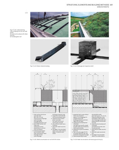
Fig. 3.14.22: water draining from a sloping roof into an outer gutter: a) construction phase with shear barriers, b) finished green roof
Fig. 3.14.23: Water channel molding
6 1
Fig. 3.14.24: Drainage and inspection shaft
7 2
7 3
4
5
1
2
8
3
4
8
1 slab surface structure: concrete slab (60 x 30 x 3.5 cm) natural stone chippings solid drainage drainage gutter building protection mat 2 plant bed framed with steel wall, waterproof screw attachment to mortar strip foundation 3 intensive planting by accumulated water filter mat (plastic fiber) drainage course solid drainage
building protection mat 4 inspection shaft (30/30) with accumulated water 5 superstructure (waterproof concrete): roof seal (root-proof) reinforced concrete 6 area without water accumulation 7 area with water accumulation 8 top edge of accumulated water 5 cm under bottom edge of intensive substrate
Fig. 3.14.25: Water accumulation on roof with 0% incline
5
6
9
1 pavement laid in area without water accumulation: approx. 3 cm chippings 2/5 crushed stone 2/32 building protection and drainage mat (car type) 2 superstructure (waterproof concrete): roof seal (root-proof), screed (outside water accumulation), reinforced concrete 3 steel band in point foundation (C12/15) 4 fiber concrete angle (15/15) on mortar bed (C12/15), root protection strip glued to angle 5 intensive planting in water
6
7 8 9
accumulation area: plant bed approx. 37–41 cm, intensive substrate, filter mat (plastic fiber), approx. 15 cm drainage course, building protection mat/protection mat superstructure (waterproof concrete): roof seal (root-proof), reinforced concrete area without water accumulation area with water accumulation top edge of accumulated water 5 cm under bottom
Fig. 3.14.26: Water accumulation with above-ground drip lip