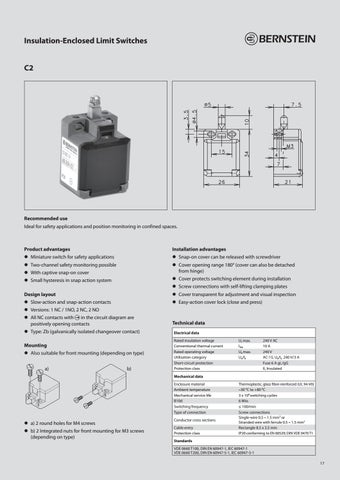
Insulation-Enclosed Limit Switches C2
Recommended use Ideal for safety applications and position monitoring in confined spaces.
Product advantages
Installation advantages
zz Miniature switch for safety applications
zz Snap-on cover can be released with screwdriver
zz Two-channel safety monitoring possible
zz Cover opening range 180° (cover can also be detached from hinge)
zz With captive snap-on cover zz Small hysteresis in snap action system
zz Cover protects switching element during installation
Design layout
zz Cover transparent for adjustment and visual inspection
zz Slow-action and snap-action contacts
zz Easy-action cover lock (close and press)
zz Screw connections with self-lifting clamping plates
zz Versions: 1 NC / 1NO, 2 NC, 2 NO zz All NC contacts with � in the circuit diagram are positively opening contacts zz Type: Zb (galvanically isolated changeover contact) Mounting zz Also suitable for front mounting (depending on type) a) b)
Technical data Electrical data Rated insulation voltage Conventional thermal current Rated operating voltage Utilisation category Short-circuit protection Protection class
Ui max. Ithe Ue max. Ue/Ie
240 V AC 10 A 240 V AC-15, Ue/Ie 240 V/3 A Fuse 6 A gL/gG II, Insulated
Mechanical data Enclosure material Ambient temperature Mechanical service life B10d Switching frequency Type of connection
zz a) 2 round holes for M4 screws zz b) 2 Integrated nuts for front mounting for M3 screws (depending on type)
Conductor cross sections Cable entry Protection class
Thermoplastic, glass fibre-reinforced (UL 94-V0) –30 °C to +80 °C 3 x 10⁶ switching cycles 6 Mio. ≤ 100/min Screw connections Single-wire 0.5 – 1.5 mm2 or Stranded wire with ferrule 0.5 – 1.5 mm2 Rectangle 8.5 x 3.5 mm IP20 conforming to EN 60529; DIN VDE 0470 T1
Standards VDE 0660 T100, DIN EN 60947-1, IEC 60947-1 VDE 0660 T200, DIN EN 60947-5-1, IEC 60947-5-1 17