19 minute read
Keys to Reliable Makeup Water Treatment for Boilers

The data indicates that a significant amount of alkalinity can be tolerated in low-pressure boilers, and for many applications, some alkalinity may be desirable, as it helps protect metal surfaces from corrosion, a point we will return to later. However, HCO3 , upon reaching the boiler, is in large measure converted to CO2 via the following reactions in Equations 2 through 4. 2HCO3 - + heat → CO3 2- + CO2↑+ H2O Eq. 2 CO3 2- + heat → CO2↑+ OH- Eq. 3 The conversion to carbon dioxide (CO2) from the combined reactions may reach 90%. CO2 flashes off with the steam, and when the CO2 re-dissolves in the condensate, it can increase the acidity of the condensate return. CO2 + H2O ⇔ H2CO3 ⇔ H+ + HCO3 - Eq. 4 Although the pH generated by this reaction has a relatively mild lower limit, the acidity is more than enough to cause significant carbon steel corrosion in condensate return systems. For example, 3 parts per million (ppm) of CO2 in pure steam condensate will lower the pH to 5.26. If dissolved oxygen is present in the system, corrosion can be greatly magnified.
A unit operation that can minimize production of CO2 in the steam generator is illustrated in the following fundamental diagram.
Figure 5: Makeup water treatment system with decarbonator.
Note the inclusion of a forced-draft decarbonator with acid injection to the feed. The acid conditioning forces Equation 4 to the left, and a well-designed decarbonator can reduce the CO2 concentration to a low parts-per-million (ppm) level. Caustic feed downstream of the decarbonator then raises the pH of the water to make it less corrosive on its path to the boiler. Note: If steam attemperation is provided by direct injection of feedwater from the deaerator, then caustic cannot be used to raise the pH. A nonvolatile compound (e.g., ammonia, an amine) is required.
Another issue briefly hinted at above now requires a bit of discussion. With too-frequent regularity, when technical representatives begin visiting a plant for the first time, they find boilers with scale deposition, corrosion, or both. In many cases, plant personnel will reveal softener problems that have led to hardness breakthroughs. Equation 1 and Figure 2 illustrate the potential effects of such difficulties. But even a softener/decarbonator operating properly still allows many ions, such as chloride and sulfate, to enter the boiler. Without close attention to boiler water chemistry and boiler blowdown control, the accumulation of these ions can cause corrosion and other problems, including foam formation in boiler drums. This in turn can lead to steam contamination and downstream issues. To re-emphasize, steam generator makeup system and boiler water chemistry control require just as much attention as process operations.
Something Better Than Softening? For modern makeup systems, reverse osmosis (RO) offers a reliable alternative to softening, where even basic systems can remove 99 plus percent of all ions from water. The osmosis process has been known for years. Two solutions of different concentrations, when separated by a semi-permeable membrane that only allows water to pass, will induce water in the dilute solution to move through the membrane to the other solution to balance the concentration. This phenomenon induces an osmotic pressure on the membrane until the solutions reach equilibrium. As the name reverse osmosis implies, the reaction is operated in reverse, and pressure produces purified water from a more concentrated stream.
The potential application of RO as a makeup water treatment method became well known in the last century and became popular with the development of and improvements to spiral-wound membrane technology.
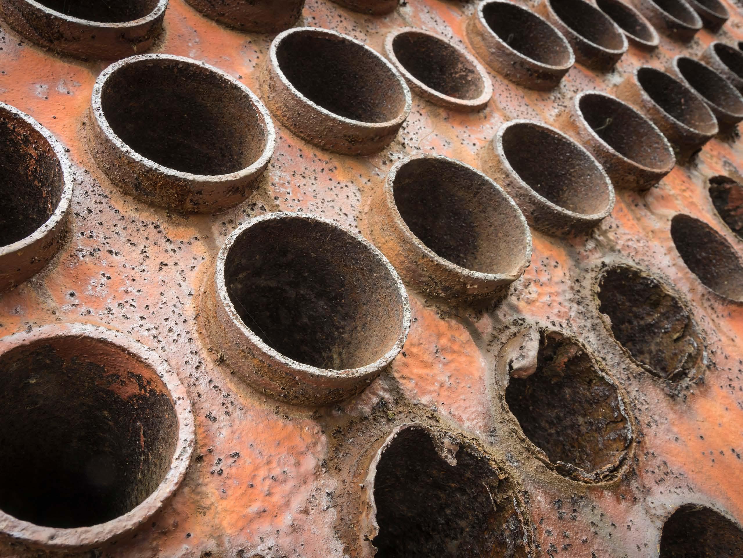
Figure 6: Cutaway view of a spiral-wound RO membrane. This photo by unknown author is licensed under CC BY-NC.
A flat membrane sheet has several layers as a backbone, which are all wrapped around a central, perforated plastic core. Feed enters the front end of each element and flows along the feedwater carrier while pressure pushes water through the membrane. The purified water, known as permeate, flows to the central core, and the increasingly concentrated feedwater (reject) exits the element. Each RO pressure vessel typically has several elements arranged in a series.
Figure 7: Basic diagram of RO elements in a pressure vessel.
O-rings seal each element along the walls of the pressure vessel so that the feedwater does not short-circuit any of the elements. A typical RO pressure vessel will have five or six elements. The configuration is designed to process the water via the mechanism known as crossflow filtration.
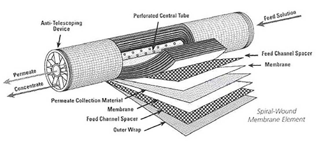
Figure 8: General schematic of crossflow filtration.
The feed flows parallel to the RO membranes, and pressure forces pure water through the membranes while the impurities are carried away with the reject. Only a few of the smaller monovalent ions (Na+, Cl-, silica, HCO3 -) pass through the membrane. However, while crossflow filtration is designed to keep impurities suspended in the reject stream, it is inevitable that even with exceptionally clean makeup, compounds will gradually build up on the membrane surfaces. Typically, residual suspended solids that are not captured by pretreatment will accumulate in the lead membranes of an RO system. Conversely, because dissolved ions concentrate as the water passes from one membrane to the next, scaling becomes an increasing concern in downstream elements.
The basic RO system is a two-stage, single-pass type, as outlined in Figure 9.
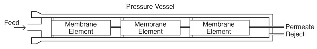
Figure 9: General schematic of a two-stage, single pass RO.
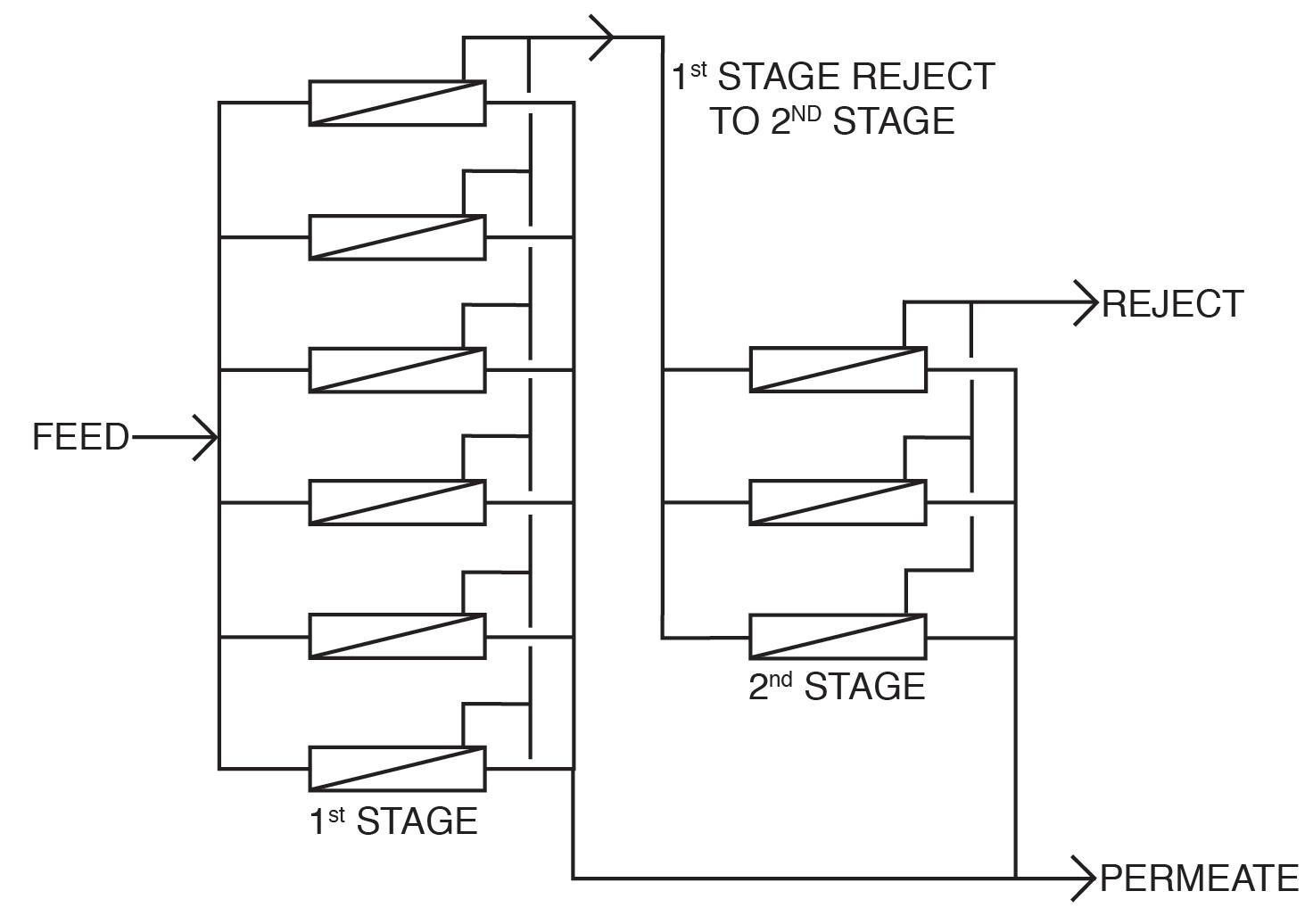
A critical feature of RO is illustrated in this diagram. With “normal” feedwaters, approximately 50% of the feedwater is converted to permeate in each first-stage pressure vessel. This means that without further processing, 50% of the feedwater would be wasted. In the two-stage design shown above, the raw feedwater flows through six parallel pressure vessels in the first stage, and the reject from these vessels is routed through three additional pressure vessels in the second stage. Total water recovery increases to 75%.
For some applications, especially those for ultra high-purity water production, two-pass RO is common. In this configuration, the permeate from the first pass is treated in a separate set of membranes. Because the feedwater has already been significantly purified, 85% to 90% recovery from the second pass is achievable. The reject is recycled back to first pass inlet, and no water is discharged to waste from the second pass. RO has become quite popular for several applications in recent years, especially for steam-based power generating units. RO plus polishing mixed-bed ion exchangers or electrodeionization can produce the high-purity water needed for steam generation.
RO Fouling and Scale Control RO membranes, especially the lead elements, are susceptible to particulate fouling. An important measurement for determining this fouling potential is the silt density index (SDI). Usually, 5-micron (µm) depth filters are placed ahead of the RO to minimize the potential for particulate fouling. The SDI tests should be performed on the effluent from these filters. The SDI test is straightforward. A flowing sample of RO feedwater, downstream of the cartridge filters, is routed through a 0.45-µm filter at 30 psig pressure. Measurement is taken of the time for 500 milliliters (mL) of water to pass through the filter at the beginning of the test (ti) and again after 15 minutes (tf). The SDI is calculated as shown in Equation 5:
SDI15 = (1-(ti/tf))/T x 100 Eq. 5 As an example, consider the following data taken from an operating RO unit: ti = 34 seconds (s) tf = 66 s T = 15 minutes (min) SDI15 = 3.2 A general rule of thumb is that the SDI should be at least below 5 and preferably below 3. However, SDI should not be the only criteria that determines suitability of a RO application. The type of water and/or the nature of contaminants should also be considered. For example, in one application, the SDI readings of the RO feed always ranged between 1 and 3. Yet the membranes fouled with exceptionally fine iron oxide particles.
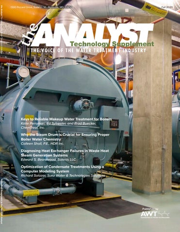
Scale formation is another issue that requires attention. When water flows through an RO pressure vessel, the concentrate continually accumulates dissolved solids, which increases the scaling potential. Calcium carbonate and sulfate can build up to a point where precipitation begins to occur. Other possible deposits include silica and alkaline metal silicates, strontium sulfate, barium sulfate, and calcium fluoride. While pretreatment can reduce the concentrations of many scale-forming compounds, the remainder may still cause problems. Barium and strontium sulfate scales are especially difficult to remove. Reputable membrane manufacturers have developed programs to calculate the solubility limits for these salts. The program will warn the user if any solubility limit is exceeded. The programs also provide “normalization” calculations of the RO system, as is described later. Antiscalant feed is typical for RO systems. Common antiscalants include polyacrylates and phosphonates. The correct antiscalant or blend can control calcium sulfate at a factor of 7 above the saturation limit, strontium sulfate 800% above the saturation limit, and barium sulfate 6,000% above the saturation limit. Pretreatment chemicals can affect membrane performance. Coagulating agents of the cationic variety and, most notably, aluminum compounds and some organic coagulants/flocculants, are particularly troublesome to RO membranes. If these agents are present, methods to remove them should be considered. Chlorine, usually introduced as bleach, injected into the primary plant makeup to control microbiological fouling will react with nitrogen atoms in RO membranes and irreversibly damage the materials. Chlorine should be removed upstream of the RO, but the absence of any biocides leaves the membranes in danger of microbial attack. Figure 10 shows how biofouling can damage a membrane element.
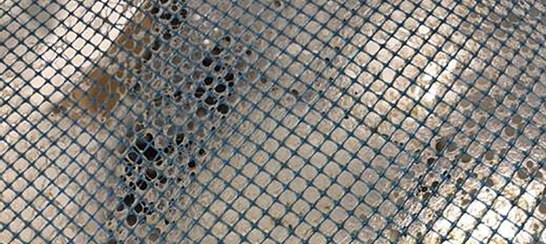
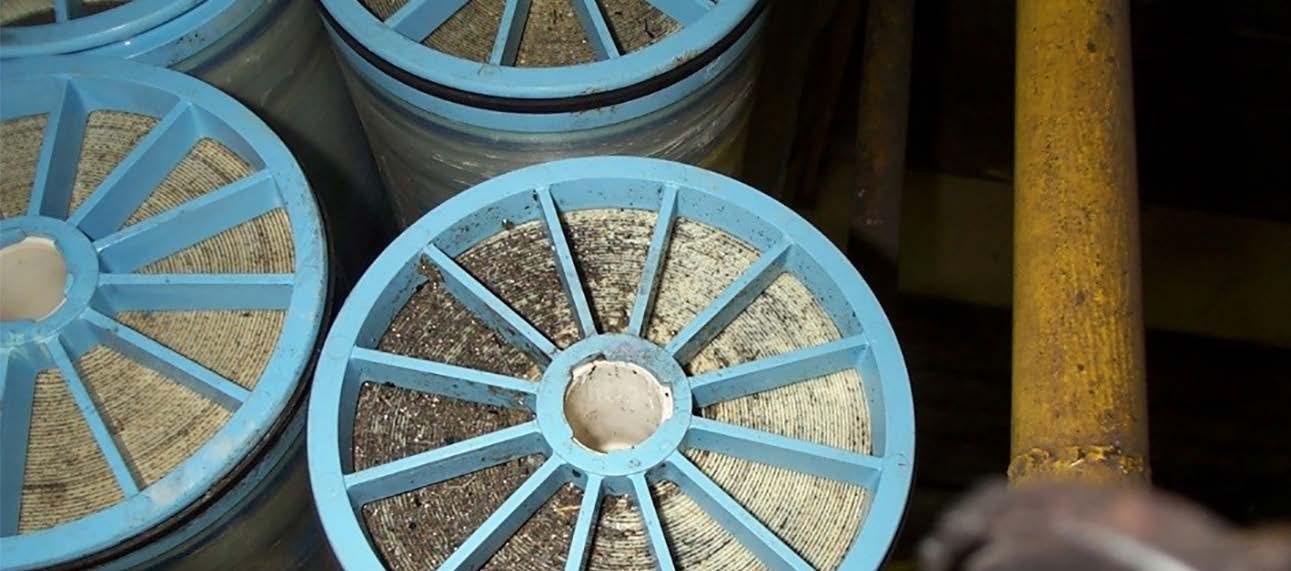
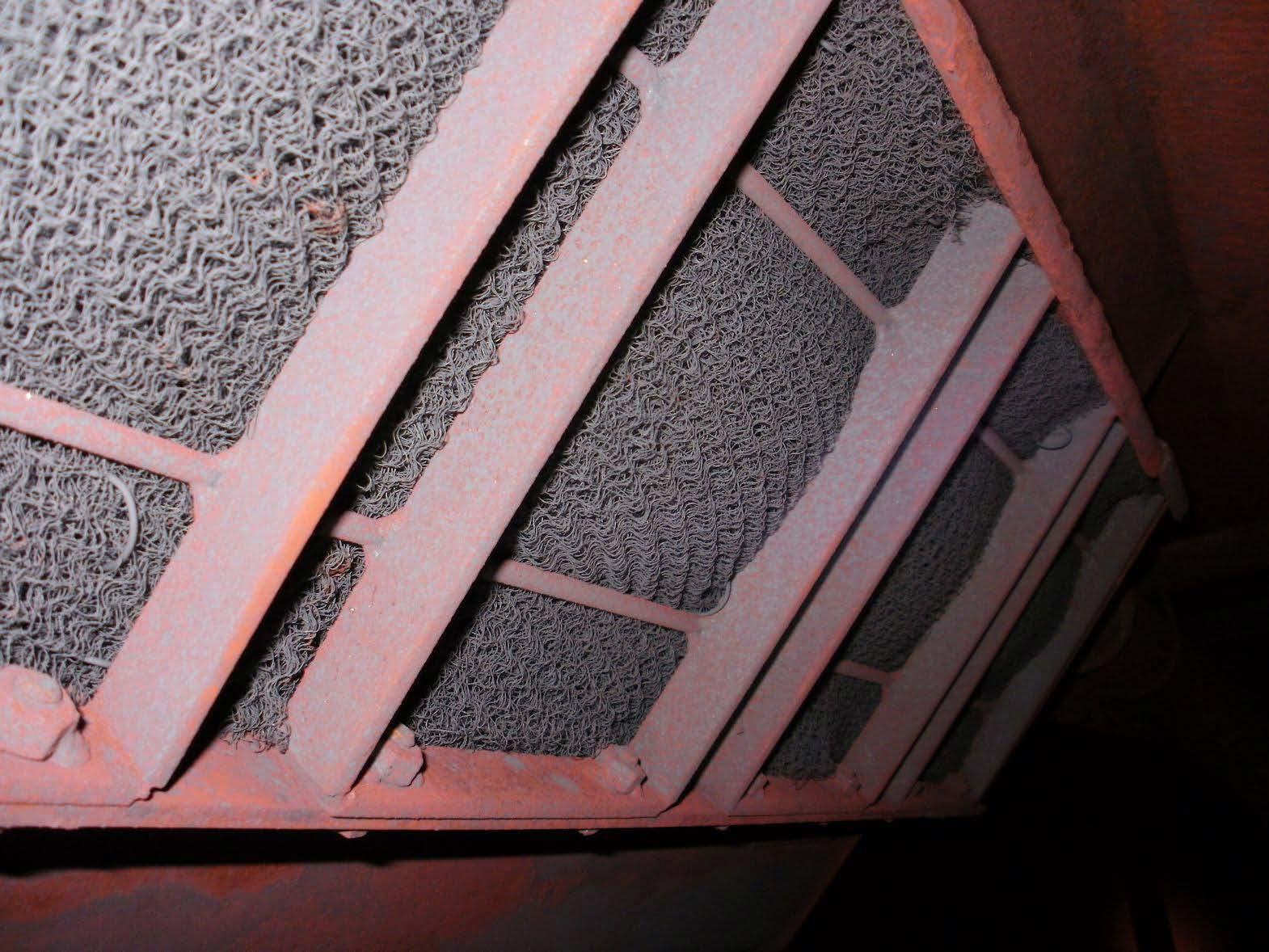
Figure 10: (Left) Severe microbiological fouling evident at the inlet end of an RO membrane. Photo by Brad Buecker. (Right) Severe biofouling on a RO membrane feed spacer. Photo by Li Yang.
Biological fouling can cause irreversible damage to membranes because the deposits cannot be completely removed by standard cleaning methods. It is imperative to minimize conditions that can lead to microbiological deposition. Alternative techniques to chlorine are available to minimize microbe deposition within membranes. One is periodic treatment with a non- or mildly oxidizing biocide (frequency depends on fouling potential). A popular choice is dibromo-nitrilo-propionamide (DBNPA). A DBNPA chemical diagram is shown in Figure 11.
Figure 11: Basic chemical structure of DBNPA.
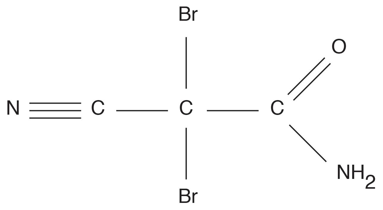
DBNPA is a fast-acting biocide that can be readily removed from any discharge by raising the pH to around 9, or commonly, treating with sodium bisulfite. Another possibility is a specialized version of chlorine dioxide (ClO2).A Such a product may sound surprising, as chlorine dioxide can act as a strong oxidizer in cooling water applications. However, in this case, the chlorine is not free, and thus does not react with nitrogen atoms in the membranes.
RO Cleaning Even with well-controlled pretreatment and antiscalant chemistry, RO membranes will still collect deposits. The lead elements gather residual colloidal and suspended solids, while the downstream elements, especially those in the second stage, see higher concentrations of dissolved ions that may precipitate. Compounding the issue is that the pressure required to push water through the membranes can hold some of these particles in place. If impurities accumulate unchecked, the eventual result is irreversible membrane fouling. Therefore, normalization programs are key for determining the need for and scheduling of RO cleanings. Temperature has a significant impact on permeate flux and pressure, and temperature changes can mask flow and pressure variations caused by suspended solids or scale buildup. Normalization programs use temperature, pressure, and flow measurements to provide corrected values for all temperature conditions. A common rule of thumb is to schedule a cleaning when the normalized value has dropped 10% to 15% from the baseline. Normalization programs can also help detect an increase in salt passage caused by a failed or degraded membrane, which might otherwise be attributed to temperature effects. A two-step cleaning process is often employed to remove the potentially wide variety of foulants that can accumulate in RO membranes. Typically, in the first step, a high-pH (12 at 95 °F) solution is circulated throughout the membranes. The alkaline solution removes organic compounds, microbiological and otherwise, that have accumulated. This stage is followed by a rinse and often a low-pH stage with citric acid as the key ingredient. Low pH helps remove soluble mineral salts such as calcium carbonate, while the citric acid will chelate metals, most notably iron. The inclusion of a heater in the cleaning loop can significantly speed up the process. An important concept is to clean each stage separately. Otherwise, extracted impurities from one stage may foul the other, and vice versa. Also, cleaning systems are typically designed with cartridge filters in the cleaning loop to collect solids during the process. These filters should be replaced after each step in the cleaning. The foregoing is general guidance only. Please consult your RO manufacturer for specific guidance.
RO Waste Stream Issues As noted, a typical two-stage, single-pass RO system recovers approximately 75% of the inlet feed and produces a waste stream (reject) of the remaining 25%. This stream must be disposed somewhere. For plants with cooling towers, the basin of one of the towers is often an ideal location for the reject. Alternately, many plants have wastewater treatment facilities to condition discharge water before release to the environment. RO reject is basically plant makeup concentrated by a factor of four, so it should not overload the wastewater treatment equipment.
Makeup Water Treatment Issues Related to Boiler Water Treatment A variety of treatment programs are available for low-pressure boilers, which may include phosphates, organic polymers, and sometimes chelating agents. These should be tailored to the chemistry of the water entering the boiler from both the makeup source and condensate return. A change from softened water to RO permeate can have a significant impact on boiler water treatment and even feedwater treatment. Higher purity waters are often known as “hungry” water because the lack of dissolved ions induces metals to give up ions to the water. Bicarbonate ions, even though they can react with calcium to form scale, will in many cases form a loose, protective layer on metals. For plant personnel considering a change from softened water to RO, these and other factors should be considered before making the switch. And, given that boilers should see a lower influx of hardness, the treatment program may need modification to account for this changed chemistry. A factor of
major importance at many plants is the ratio of makeup water to condensate return. If the latter is much higher than the makeup flowrate, condensate return chemistry can dominate the selection of the best boiler water treatment program.
Reference 1. ASME (1994). “Consensus on Operating Practices for the Control of
Feedwater and Boiler Water Chemistry in Modern Industrial Boilers,” The
American Society of Mechanical Engineers, New York, New York.
Endnote AChemTreat’s CL3000, a specialized version of chlorine dioxide (ClO2), is the cleaning product referenced in the text.
Disclaimer: This discussion represents good engineering practice developed over many years. However, it is the responsibility of plant owners, operators, and technical personnel to set up reliable chemical feed, control, and monitoring systems based on consultation with industry experts. Many additional details go into the design and subsequent operation of these technologies than can be outlined in this article. Katie Perryman is manager of ChemTreat’s pretreatment team as well as the company’s Early Career Program. Her career at ChemTreat has focused on membrane separation and ion exchange with an emphasis on consulting and troubleshooting of pretreatment systems in different water treatment applications. Ms. Perryman holds a B.S. in chemistry from Virginia Tech. She may be contacted at katieh@chemtreat.com. Ed Sylvester is the director of filtration, ion exchange, and membrane technologies at ChemTreat. He has more than 41 years of experience in water treatment, including product development, troubleshooting, corporate training, and conference presentations. Mr. Sylvester may be contacted at edwards@chemtreat.com. Brad Buecker is senior technical publicist with ChemTreat. He has many years of experience in or affiliated with the power industry, with nearly two decades of it in steam generation chemistry, water treatment, air quality control, and results engineering positions. Mr. Buecker has authored many articles and three books on power plant water/steam chemistry and air pollution control topics. He has a B.S. in chemistry from Iowa State University. Mr. Buecker can be reached at bradley.buecker@chemtreat.com.
People crafted solutions since 1976.
Custom Blender. super savvy.

Our people blend solutions, not chemicals. We manufacture a broad line of proven products for treating any size of commercial or industrial boiler, cooling water, closed loop, airwasher, or wastewater systems.
› Expert Technical Assistance › Biocide Sub-registrations Available › Private Labeling, Product Bulletin and MSDS Services › Water, Deposits and Corrosion Coupon Analysis Services › PTSA Dye Trace Cooling Products
Request a FREE CONSULTATION before your next project 423.698.7777 | BrowneLaboratories.com
Warehouse Staff Want in TOTES and DRUMS?

BUTTRESS COARSE THREADING for QUICK VACUUM PREVENTION NTP BUNG THREADING for PUMPS and VALVES
E
CARBOYS and DELL DRUMS for SMALLER NEEDS CAM-LOCK QUICK DISCONNECT
BALL VALVES for MULTI-USE LEAK PREVENTION
E
EASY SHIP PAILS with POUR SPOUT
Shipping U.S. Specification drums and totes. We care about the details. Just like you.
Why the Steam Drum Is Crucial for Ensuring Proper Boiler Water Chemistry
Colleen Sholl, P.E., HDR Inc.
Abstract While the boiler steam drum is often seen as simply a storage vessel where water and steam separation occur, it is a far more complex part of the overall steam/water cycle. Mechanical and operational problems in the steam drum can have a significant impact on cycle chemistry and, therefore, the rest of the plant. Improper operation, mechanical issues, or lack of routine maintenance can cause poor steam quality, poor boiler water quality, and corrosion or deposition of downstream equipment. This article will discuss examples of mechanical and operational problems commonly experienced with boiler steam drums and the impacts that these problems can have on cycle chemistry using a case study approach. It will describe the recommended methods and procedures for conducting routine drum testing to aid in identification of developing or trending issues. Introduction Whether one is considering a traditional boiler steam drum or steam drums on a heat recovery steam generator (HRSG), the steam drum is viewed by some as a wide spot in the line or, more frequently, as a simple storage vessel where water and steam separation occurs. True, water and steam separation occur here, but it is that very fact that makes the operation and maintenance of the steam drum and its ancillary equipment key factors in achieving good cycle chemistry control throughout the entire steam/water cycle. Steam separation typically occurs in two stages within a steam drum—primary separation and secondary separation. Primary separation is normally accomplished with baffles and centrifugal, inertial, or chevron-type separators. Secondary separation is generally achieved using mesh pads, screens, or corrugated
plates framed at the steam outlet of the drums that act as final stage scrubbers. Effective separation is a function of both design and operational factors. Design factors include items such as drum dimensions (length and diameter), type and arrangement of separation equipment, and arrangement of drum inlet and outlet connections—factors that are pre-existing and out of the control of plant operational staff (1). The operational factors or how the plant is run are the factors that plant operational staff can control or influence and include drum level control and surges or swings in plant operations. High-efficiency separation is crucial in minimizing carryover of water droplets, which can cause thermal damage in downstream equipment, and carryover of dissolved solids present in those water droplets, which can result in the formation of deposits in downstream equipment (1). Very few plants today perform routine carryover testing of their steam drums. Online continuous monitoring of a limited number of steam purity and drum water quality parameters has taken the place of routine carryover testing. Performance of this testing on a routine basis can serve as an important cycle chemistry troubleshooting tool, as carryover due to mechanical or operational issues (i.e., poor steam separation) is the most common cause of drum-related cycle chemistry issues. Carryover testing should be performed every six months at a minimum, and more frequently if the unit has a history of carryover problems or a problem is suspected. For this assessment, sodium is most commonly used as the tracer ion for testing since online analyzers for determining low-level sodium are commonly provided, and sodium salts such as sodium hydroxide and/ or trisodium phosphate are used for pH control in many steam drums, making supplementary chemical additions unnecessary or at least minimizing a supplemental addition. These sodium salts also have good solubility and a relatively low volatility at typical drum operating conditions, making them suitable tracers for testing purposes (2).
Drum Carryover Testing Preparation for assessment. Carryover testing should be conducted at stable full load unit operating conditions. The rate of carryover is dependent on steaming rate (unit load), drum operating pressure, and drum water level. Carryover generally increases slowly as the unit approaches full load and then quickly peaks at its maximum. Drum level can also impact carryover, with higher than normal drum levels resulting in higher carryover rates. Normalizing unit operations at full load design operating conditions prior to conducting the testing standardizes the results for comparison during future tests and provides the best conditions for check against design parameters. It may be desirable to also conduct the same testing at additional loads at which the plant frequently operates to provide additional data for troubleshooting suspected carryover problems or for making chemistry adjustments. Drum blowdown should be placed in manual (if automatic control is provided) and maintained at a constant flowrate throughout the duration of the testing. Prior to beginning carryover testing, any issues or upset conditions associated with chemical additions should also be resolved and chemical concentrations stabilized. Previous carryover testing results and steam drum mechanical carryover design data should be available for evaluation purposes once the test data is collected. Figure 1 shows the primary (top) and secondary (bottom) steam-water separation equipment.
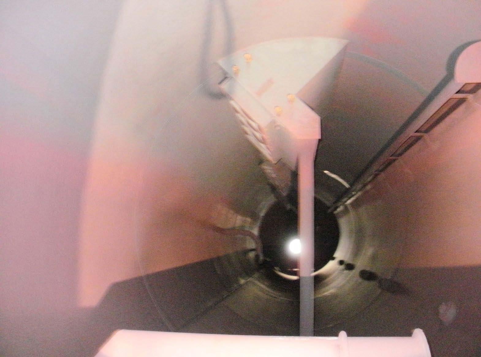
Figure 1: Primary (top) and secondary (bottom) steam-water separation equipment.
If using online sodium analyzers for testing, the units should be configured to sample and test for saturated steam and for drum blowdown for the unit to be tested and the sample lines flushed. Separate analyzers are needed for testing the saturated steam and the blowdown to avoid cross contamination of samples and to provide timely samples. If two independent sodium analyzers are not available, utilizing another testing method for the blowdown is preferred since the concentration of sodium in the