

Installation & Operation Manual Swimming Pool Heat Pump Model No.: BYC-007TD1 Thank you very much for purchasing our product,please keep and read this manual carefully before you install heat pump.
Fluorinated greenhouse gas – (R32)

The device contains the fluorinated greenhouse gas (R32) which is required for the device to work.
Industrial designation HFC 32
Common designation R32
Global warming potential (GWP) 675
Further information can be found on the device itself or the Specifications.
WARNING!
Risk of fire and explosion through leaking finned heat exchanger!
The refrigerant circuit of the finned heat exchanger contains highly pressurised, easily flammable, odourless gas. Risk of fire and explosion in the event of uncontrolled gas leakage
- Action of filling gas must be conducted by professional with R32 operating license.
- Keep the heat pump away from heat sources and naked flames.
- Do not drill into or scorch the heat pump.
- Do not use any objects apart from those permitted by the manufacturer to speed up the defrosting process.
- Immediately shut off the heat pump if you suspect a gas leakage
- The refrigerant is odourless. Always keep ignition sources away from the installation site of the heat pump.
- Contact an authorized expert if you suspect a gas leakage
WARNING!
Risk of electric shock!
A faulty electrical installation or a mains voltage that is too high can lead to electric shock.
- Have the installation, initial start up and maintenance of the heat pump carried out by authorized technician only.
- Please always cut the power supply if you want to open the cabinet to reach inside the heat pump as there is high voltage electricity inside.
- Only start work on the heat pump after checking all safety regulations.
- Only connect the heat pump if the mains voltage from the power socket matches the voltage indicated on the rating plate.
- Do not operate the heat pump if there is visible damage or the mains cable or the mains plug is defective.
- Do not open the housing. Leave repairs to qualified specialists. Liability and warranty claims are
excluded in the event of repairs carried out on your own, improper operation.
- Ensure that children do not insert any objects into the fan blade and heat pump.
- Ensure that the electrical system to which the heat pump is connected has an earth conductor.
- If the unit would be installed where is vulnerable to lightning stroke, lightning protection measurements must be carried out.
ATTENTION!
- The manufacturer declines any responsibility for the damage caused with the people,objects and of the errors due to the installation that disobey the manual guideline. Any use that is without conformity at the origin of its manufacturing will be regarded as dangerous.
- Please always keep the heat pump in the ventilation place and away from anything which could cause fire.
- Don’t weld the pipe if there is refrigerant inside machine. Please keep the machine out of the confined space when make gas filling by the authorized technician.
- Please always empty the water in heat pump during winter time or when the ambient temperature drops below 0℃, or else the Titanium exchanger will be damaged because of being frozen, in such case, it will be out of warranty for this machine
Content Accessories description............................................................................3 Attention for safety..................................................................................4 Installation of the unit.............................................................................5 Specifications..........................................................................................9 Electrical Wiring.....................................................................................10 Instruction of operation ........................................................................12 Adjusting and Initial operation...............................................................18 Operation and maintenance..................................................................19 Error codes & Solutions...................................................................... ...21 WiFi-Function........................................................................................23
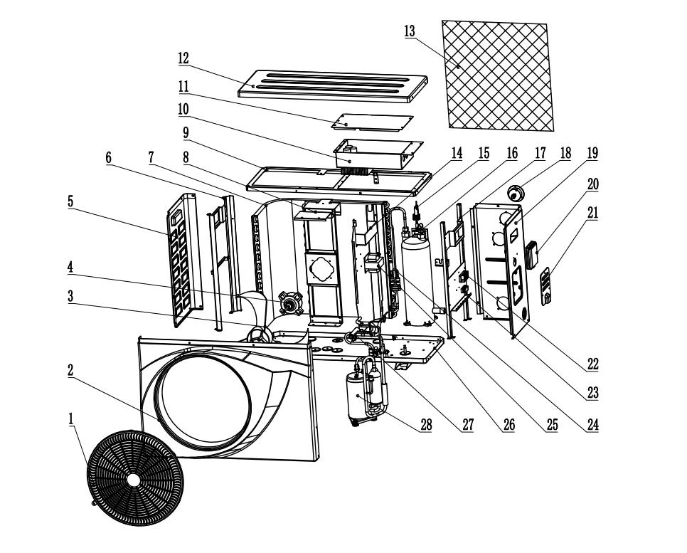
1. Accessories description

Each unit produced by our factory is with the following accessories:
No. Name Qty. Use
1 Instruction Manual 1 PC Guide users to install the system 2 Drain pipe 1 PC Used for draining the condensate water 3 Drain pipe connector 1 PC Connect the drain pipe to the heat pump unit 4 Rubber shock absorber 4 PCS Reduce vibration and reduce noise 5 Heat pump unit 1 SET For heating water 6 Water connection 2 SET Connect the piping system

For function you need to purchase at least the following parts for each unit:
No. Name Qty. use
1 Water pump 1 Cycle the heated water 2 Filter system 1 Protect the heat pump from pool water 3 Water pipes system 1 Connect the equipment and make circulation
NOTE
The types and quantity of the water pipes, valves, filter equipment, sterilizing equipment which used for the swimming pool heating/circulation pipe system, depend on the project design. We suggest not to install auxiliary electric heaters in the system. If must install auxiliary electric heaters, it should be operated by the specialized persons, and our company has no responsibility for all the problem cause by the auxiliary electric heater.
Illustrations of machine
2. Attention for safety
Range of application:
1.Power supply: 220V/1N~50/60Hz.
2.Environment temperature: 15°C〜43°C
3.Water temperature range: 8°C~40°C in Heating function 8°C~28°C in Cooling function
● Confirm the ground connection, if the ground connection is not correctly done, it may cause electric shock. And please cut off the power in the lightning storm weather.
● If install the heat pump in a small room, it must keep good ventilation.
● The main power switch should be out of the reach of Children.
● Don't put finger or stick into the air inlet or air outlet as the high speed rotor may cause injury.
● When an exception happened (burning smell etc..), turn off the manual power switch immediately and contact with after sale service department.
● When the unit needs to be removed or re installed or repaired, please entrust after sale service department and specialized personnel to do it. If the installation/ maintainence is not well done, it may cause unit operation failure, electric shock, fire, hurt, leaking, etc.
● Must not be unauthorized reformed, otherwise it may cause electric shock or fire.
● Must not install the unit with combustible around.

● Confirm the installation base is strong enough to avoid falling of the heat pump.
● Confirm leakage protection switch is installed to avoid electric shock or other issues.
● When cleaning the unit, the operation should be stopped, and power switch should be turned off.
3.1 Installation Illustration
3. Installation of the unit
Above illustration is just for the reference, please take the advice of authorized installers.
3.2 Advised installation space
Keep the following indicated space for operation and maintenance when make the installation.


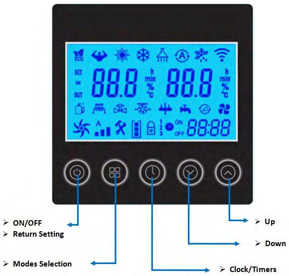
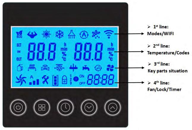
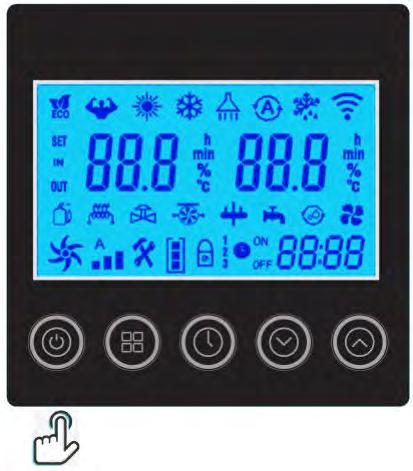
Start up & Locking
Press the button to switch the heat pump on or off. This button is also used to return to the main interface.
When the heat pump is in operation, hold the button for 3 seconds to lock or unlock the controller. (The lock is activated automatically after 60 seconds of inactivity). When the display is locked, the logo appears.

* Please unlock the controller before the other operations every time.
Attention: Before you start, make sure the filtration pump is running and that water is flowing through the heat pump.
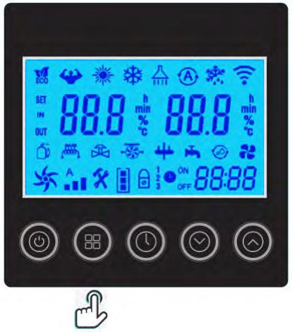
6.4 Operation Mode Selected
Hold the button for 3 seconds to change the below four operating modes each time:


:Mode ECO Inverter: Choose this heating mode that the heat pump operates silently.
:Mode Boost Inverter: Choose this heating mode that the heat pump operates powerfully

: Mode Cooling Inverter: Choose this cooling mode that the heat pump intelligently cools the water of your pool
: Mode Auto: The heat pump can switch Heating and Cooling function automatically
6.5 Set the required temp.
On the main interface, press and to adjust the desired water temp. of your pool, then press the to save the setting.


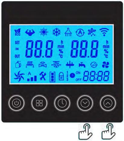
When setting the water temp., the icon ‘SET’ will light on, the left one is Setting temp., the right one is the Outlet water temp.
After finished the setting, the icon ‘SET’ will extinguish, the left one will become Inlet water temp., the right one Outlet water temp.
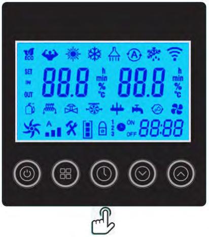
6.6 Clock setting
Press the button to enter the clock setting interface. Clock display on right bottom flashes.


Change the hours using and , then press again to go to minute setting, change the minutes using the and
Press again to confirm the setting and return to the main menu.
6.7 Timer setting
Hold the button for 3 seconds to enter the setting of Timer ON & Timer Off groups. will flash, then set the Turn On and Off timer like the Clock setting.

Pay attention: There are 3 groups Timer for your every day setting.
You can press to save the current setting and go back to the main interface.


Cancel the Timer: Hold the button for 3 seconds to cancel all the timer setting.
6.8
Definition of
other
Fan Speed : Signal of Water pump : Wi Fi function
icons : Defrosting :Compressor : 4 way valve
A 1 ON OFF 2 3
Attention: With the indication of the functions or key parts, it is helpful for service team to maintain or repair the heat pump.
6.9 Manual defrosting
Hold and for 3 seconds to start Manual defrosting function.
Hold and and and for 5 seconds to recover factory setting.
6.10 Factory setting recovery
Press to enter the Running parameters checking, then press and to check the below parameters as below: N° Description Unit C01 Ambient temperature °C C02 Evaporator coil temperature °C C03 Exhaust temperature °C C04 Return temperature °C C07 Titanium heat exchanger temperature °C C08 Water inlet temperature °C C09 Water outlet temperature °C
6.11 Running Parameter checking
C13 Temperature sensor failure
C14 Refrigerant system failure
C15 Inverter driver failure
C16 Device output
C17 Running status
C18 AC voltage V
C19 DC voltage V
C20 Actual frequency Hz
C21 EEV open degree
C23 Heat pump current A
C24 Compressor current A
C25 DC fan motor1 speed Rpm
C26 Compressor target frequency Hz
C27 DC fan motor2 speed Rpm
C28 Control system software version
C29 Driver software version
C30 Controller software version
6.12 Parameter setting
Hold and for 3 seconds to enter the Parameter setting, press to select the parameter, then press and to set the new data for the below parameters.
Code Description
P01
P02
P03
Default Scope
Inlet water temp. in Heating mode 27℃ 8~40℃
Inlet water temp. in Cooling mode 27℃ 8~28℃
Inlet water temp. in Auto mode 27℃ 8~40℃
P04 Water temp. difference before restart 1℃ 1~18℃
P05 Heat pump ON/OFF when reached the desired water temp. 1 1 ON, 0 OFF
7.Adjusting and Initial operation
7.1 Attention
● Open the valve of water system, and the valve of assistant tank, inject water into the system, and exhaust air inside.
● Do adjustment after electrical safety inspection.
● After the power is switched on, start the test running of heat pump, to see if it can function well.
● Forced operation is forbidden, because it is very dangerous to work without protector.
7.2 Preparation Before Adjustment
● The system is installed correctly.
● Tubes and lines are putted in the right place.
● Accessories are installed.
● Ensure the smooth drainage.
● Ensure the perfect insulation.
● Correct connection of ground lead.
● The supply voltage can meet the requirement of rated voltage.
● Air inlet and outlet function can work well.
● Electrical leakage protector can work well.
7.3 Adjustment Process
● Check if the switch of the line controller can work well.
● Check if the function keys of the line controller can work well.
● Check if the indicator light can work well.
● Check if the drainage system can work well.
● Check if the system can work well after starting up.
● Check if the water outlet temperature is acceptable.
● Check if there is vibration or abnormal sound when the system is functioning.
● Check if the wind, noise and condensate water produced by the system affect the environment around.
● Check if there is refrigerant leakage.
● If any fault occurs, please check the instructions first, to analyze and remove the fault.
8. Operation and maintenance
8.1 To ensure the well functioning, the system should be checked and maintained after a period of time. During the maintenance, please pay attention to some points below:
● When you need open the cabinet and make inside inspection, please do cut off the electricity power in advance.
● To ensure the stable running, please do not adjust any setting.
● Pay close attention to whether all the operation parameters is normal during system working.
● Examine regularly whether the electrical connection is loose, if yes, fasten it on time.
● Examine regularly the reliability of the electrical components, change all the failed or unreliable components on time.
● The dirt retention on the surface of evaporator fin should be cleaned every 6 months.
● After long downtime, if we restart the equipment, we should make following preparations: examine and clean the equipment carefully, clean the water pipeline system, examine the water pump, and fasten all the wire connections.
● Replacement parts must use the original accessories, can not be replaced by other similar accessories.
8.2 Refrigerant filling
Examine the refrigerant filling condition through reading the data of gauge, also the air suction and exhaust pressure. If there is leakage or changing components of the refrigeration circulation system, please ask for the assistant of professional technicians.
8.3 Leak detection
During leak detection and air tightness experiment, never let the refrigeration system filling oxygen, ethane or other flammable harmful gas, we can only adopt compressed air, fluoride or refrigerant for such experiment.
8.4
Drainage water in heat exchanger
If the heat pump will be not used for a long time or in winter season, please do drain the water inside heat exchanger to avoid broken when freezing.
8.5 To remove the compressor, please follow the following steps
● Turn off the power supply
● Exhaust the refrigerant from the low pressure end, attention to reduce the exhaust speed, and avoid frozen oil leakage.
● Remove the compressor air suction and exhausting pipe.
● Remove the compressor power cables.
● Remove the compressor fixing screws.
● Remove the compressor.
8.6 Conduct regular maintenance according to the user manual instruction, to make sure the unit running in good condition.
● Fire prevention: if there is a fire, please turn off the power switch immediately, put the fire out with fire extinguisher.
● To prevent flammable gas: the unit working environment should stay away from gasoline, ethyl alcohol and other flammable materials, to avoid explosion accident.
Code Description
E03 Water flow protection
E04 Antifreeze protection
9. Error codes & Solutions
Potential reasons
Insufficient water flow
Solutions
Check the water circuit system, the opening of by pass kits, the running of water pump
Water flow switch disconnected Check the wiring and reconnect water flow switch
Water flow switch defective Change a new one
Ambient/Inlet water temp. is too low and the unit is on standby
The unit will be re started when the ambient/inlet water temp. goes up.
E05 High pressure protection
E06 Low pressure protection
E09
E10
Connection failure between PCB and controller
Communication failure between PCB and driver module
E12 Exhause temp. too high
Insufficient water flow
Check the water circuit system, the opening of by pass kits, the running of water pump Ambient/ Water temp. is too high
Fan motor speed is abnormal or fan motor has damaged
Check the fan motor Excess refrigerant gas
Readjust the refrigerant volume High pressure switch disconnected or defective Reconnect or replace high pressure switch Piping system jammed
Check the piping system
Bad ventilation
Check the installation circumstance. Clean the evaperator. Check the running situation of fan.
Low pressure switch disconnected or defective Reconnect or replace low pressure switch
Gas leakage (Check the gauge)
Detect the leakage point and make the maintainence
Fan motor speed is abnormal or fan motor has damaged Check the fan motor EEV blocked or piping system jammed Check the piping system
Bad wire connection
Check the wiring Defective controller Change a new controller Defective PCB
Change a new PCB
Check the wiring Defective PCB Change a new PCB
Bad wire connection
Insufficient water flow
Lack of gas
Check the water circuit system/ water flow switch
Check if there is a gas leakage
Piping system jammed Check the piping system Exhause piping temp. sensor (Purple connector) detective
Change a new sensor
E15 Inlet water temp. sensor (Blue Sensor disconnected or defective Reconnect or replace sensor
connector) failure
E16 Outer piping temp. sensor (White connector) failure Sensor disconnected or defective Reconnect or replace sensor
E18 Exhause piping temp. sensor (Purple connector) failure Sensor disconnected or defective Reconnect or replace sensor
E21 Ambient temp. sensor (Black connector) failure Sensor disconnected or defective Reconnect or replace sensor
Insufficient water flow
E22 Difference of outlet and inlet water temp. too high
E23 Overcooling protection under cooling mode
Check the water circuit system/ water flow switch
Outlet water temp. sensor (Red connector) failure Change a new sensor
Inlet water temp. sensor (Blue connector) failure Change a new sensor
Insufficient water flow
Check the water circuit system/ water flow switch
Outlet water temp. sensor (Red connector) failure Change a new sensor
E27 Outlet water temp. sensor (Red connector) failure Sensor disconnected or defective Reconnect or replace sensor
E29 Suction piping temp. sensor (Yellow connector) failure Sensor disconnected or defective Reconnect or replace sensor
E30 Low ambient temp. protection
E32 Overheating protection under heating mode
Beyond the scope of using temp. Stop using Ambient temp. sensor (Black connector) failure Change a new sensor
Insufficient water flow
Check the water circuit system/ water flow switch
Outlet water temp. sensor (Red connector) failure Change a new sensor
E33 Piping temp. too high protection under cooling mode
E34 Compressor start up failure
Ambient/water temp. is too high under cooling mode
Check the scope of using Refrigerant system is abnormal Check the piping system
Bad wire connection for compressor Check the wiring
Wrong phase connection for compressor Check the wiring PCB failure Change a new one
E35 Compressor over current Power supply is abnormal Check the power supply
E36 Compressor output failure
Wrong phase connection for compressor Check the wiring
E42 Inner piping temp. sensor (Green connector) failure Sensor disconnected or defective Reconnect or replace sensor
E46 DC fan motor malfunction
Bad wire connection Check the wiring of fan motor Fan motor defective Change a new fan motor


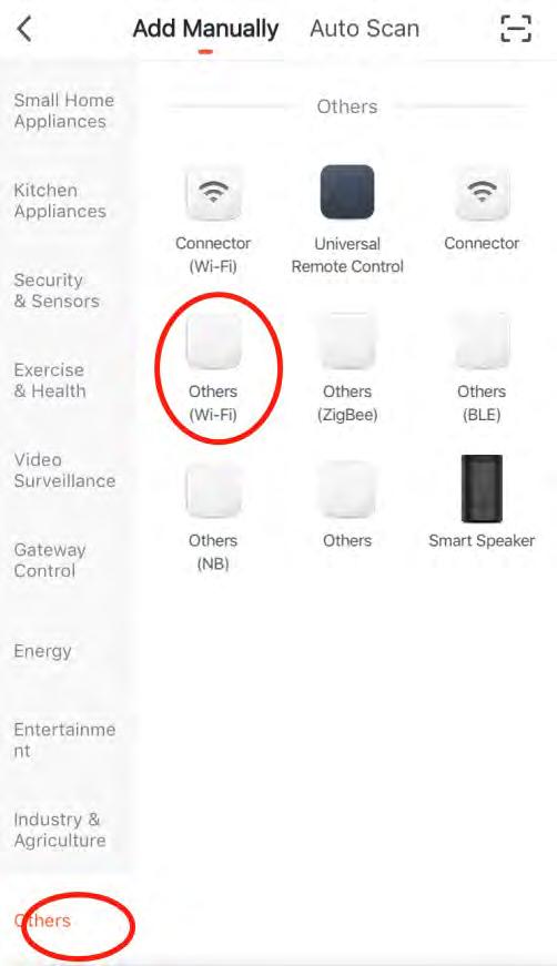
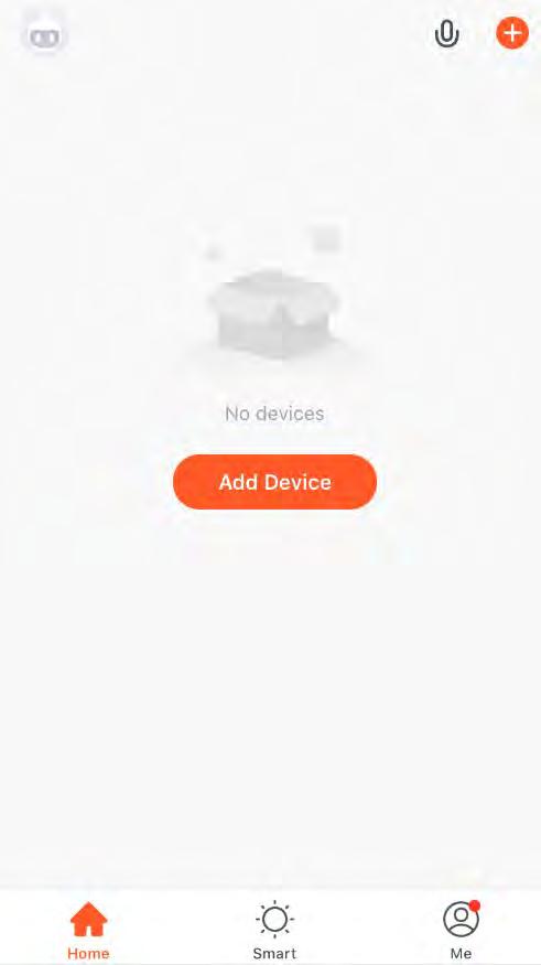
1. Download the ‘Tuya Smart’ App Scan the QR code below to download the mobile APP. Or search ‘Tuya Smart’ in App Store (IOS) or Google play (Android) 2. Sign up for the first time 10. Wifi-Function
3. Press ‘ + ’ to add a device 4. Choose ‘Others’ and ‘Other Wifi’ on the interface
5. Put your mobile phone close to the pool heat pump, which are under the same Wifi area
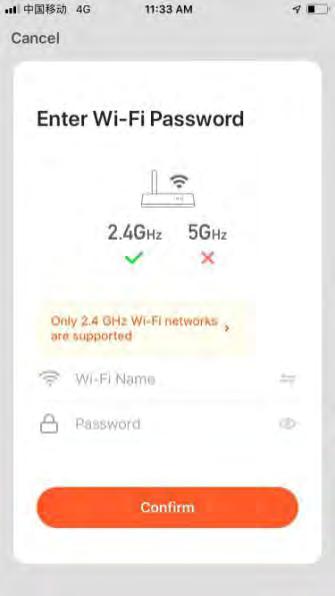
6. Make sure the device is reset, then enter the WIFI account and password to connect Wifi.
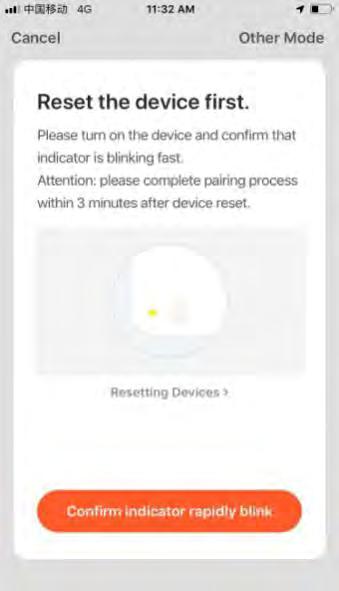
Reset the Wifi function: Hold the and and for 3 seconds.
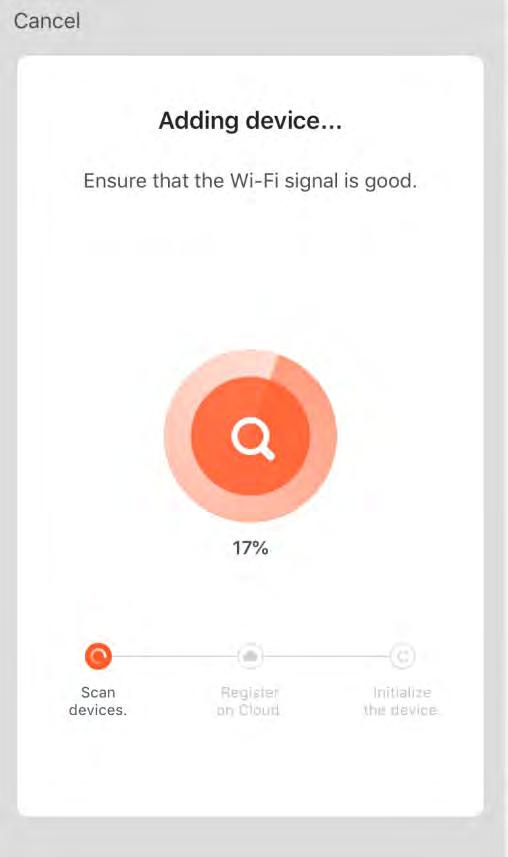
7. Press ‘Confirm’ to start the connection after completing. The device is successfully added if it’ s connect, then press ‘Finish’


8. App Main Interface 9. Functions Remark: The heat pump APP function includes: Turn On/Off the machine Temperature setting and display Mode Selection Failure status display