8 minute read
The case of a Crafty Crafter


Autotechnician contributor Gareth Davies, who runs a German car specialist workshop in South Wales, shows no matter how familiar you are with a brand or model, every day’s a school day
We recently received a job from a local independent garage. The vehicle in question was a 2014 VW Crafter 2.0 tdi CKTC engine code. The job sheet described a lack of power, an engine management light and coil warning light on the dashboard. From the diagnosis carried out, they had established there was a boost pressure fault code, and that data retrieval was limited given the tooling available.
I must admit, I do love a good Crafter or Sprinter. Whether it be carrying out general mechanical repairs, or in-depth diagnosis, we have looked after a fleet of them, around 100 or so, over the last 7 years, so we have become fluent in their behavior, and their failures. But there is always one waiting in the wings to show you something you haven’t personally seen before.
An initial fault code report using ODIS showed faults stored for charge air pressure positioner, implausible signal. I was satisfied with the nature of the fault and description that I wouldn’t necessarily need ODIS to proceed in terms of TPI’s or procedures and that a more ‘user-friendly’ weapon of choice could be used in terms of displaying data, clearing faults and carrying out final control tests, if required.
Upon lifting the bonnet it was clear quite a lot of repairs had been carried out, so before proceeding, I had a quick chat with the garage to get a clearer picture of events, which may or may not help me to help them identify the issue quicker. It had experienced cooling system faults, which were traced to the EGR cooler, but had been driven for an extended period with the fault – this had resulted in damage to the head gasket. The cylinder head had been refaced and a new gasket and associated parts replaced, along with a new genuine EGR cooler (separate to the valve on this model). In addition, a new turbocharger was present, including electronic actuator. It was mentioned that a boost pressure issue had arisen not long after

engine repair. The actuator was reported faulty on the old unit and a new complete turbocharger was replaced (non-genuine, aftermarket). The actuator on this model like many VAG models has a vacuum adjuster with electronic feedback for control.
Initial readings
Armed with all the information needed, I went for a road test to acquire some data and verify symptoms. The van had very little oomph in it and quite quickly limped, so I returned to carry out some testing. First port of call was to test the instruction to the turbocharger to work (final control diagnosis).
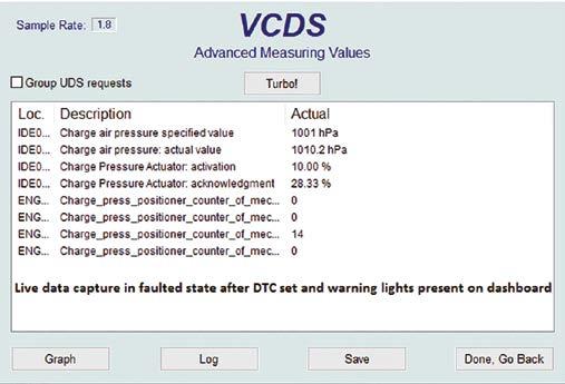
After clearing the faults and carrying out an actuation, the live data showed little moved, but had plausible rest readings for the positioner. When the duty cycle would normally change, the values went skewwhiff and the coil light followed by engine management light would appear on the dashboard.
The position sender is nothing more than a potentiometer with three wires. A 5v feed, a ground and a signal wire. The theory is depending on position, the signal voltage will change upon operation (feedback) as long as the 5v feed and ground to the unit is good. Armed with my meter back probing at the actuator (engine on and running with component connected) I found a good 5v feed present, cross checked against the ground at the plug and chassis ground. I then cross checked the ground at the component in the same way. All checked out at 4.99v with no volt drop across either wire. The relevance of this test is because I have had several crafters previously with volt drop across this harness over on the NS of the engine harness, causing all manner of weird and wonderful faults. Not this one.
The next test was to examine the signal wire behavior. General signal operation would be expected to be between 0.5v-4.5v, particularly as it is a component on the 5v reference circuit, and as a result is monitored. The ECU would then know operation outside of these parameters would be a wire or component fault. In this instance, 0.45v at rest was measured. I observed no change with engine on or off. At this point, I had to advance the test plan somewhat. What causes the positioner to move? Vacuum, of course. To prove a component’s function before looking further afield, I used my Mityvac to check the range of signal output from the positioner when controlled by myself. I found that from rest, if I applied a vacuum to the actuator, I could manipulate a signal voltage from 0.45v right the way around to 4.6v. Confirming that when carrying this out I had full movement on the actuator arm connected to the turbocharger, I was happy (short of some tweaked adjustments) that this turbocharger and actuator had the ability to work if controlled. To further bolster the test result, I checked live data at two states when controlled by myself, and the charge air pressure value changed accordingly. We
Signal checks
were getting somewhere.

We then had to test whether the instruction/command from the ECU from a vacuum side of things was corrupt. With my vacuum gauge connected in place of the actuator, an assistant started the engine, and it was recorded that barely 5in/mg was recorded at the turbocharger actuator. This is not enough to move the positioner, but was it being controlled in this manner? Another final control test of the turbocharger showed no increase in vacuum when instructed.
Industry Leading Diagnostic Solutions Coupled With Expert Diagnostic Support From IVS 360 OEM Master Technicians


Click Here To Find Out More About Opus IVS solutions
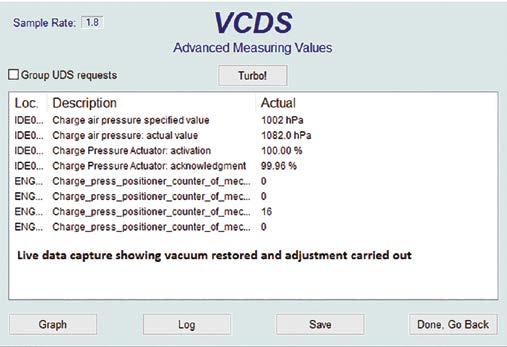
Live data capture showing boost pressure restored on road test
Working back following the breadcrumbs, I saw a new N75 (the solenoid that controls the actuator) had been fitted. Measuring the vacuum supply to this unit (vac in was tested to ensure supply was good to see if we were dealing with a faulty new component or little to no vacuum supply to unit) found that again barely 5in/mg was present to the unit. Knowing the trouble we have also had with vacuum pumps on this model, I went straight to the vacuum pump itself. Measuring vacuum directly off the pump, I showed a healthy and instant 30in/mg. In a methodical manner, working away from the pump toward the actuator (it’s a pretty busy vacuum circuit on this model) I came across a busy cluster of tee’s and a 1-way valve. I was able to trace the loss from 30in/mg to 10in/mg after the one-way valve, where the vacuum pipe is connected to the integrated storage reservoir built into the rocker cover itself. When crimping that pipe with my gauge tee’ d into the system for monitoring, I was able to manipulate the readings from 30in/ mg pipe crimped, to 10in/mg pipe uncrimped.
After some minor adjustments to the routing of the pipework to bypass the reservoir, I attempted a turbocharger final control output again, this time with better results. The charge pressure readings now changed, and movement from end stop to end stop was witnessed with the actuator.
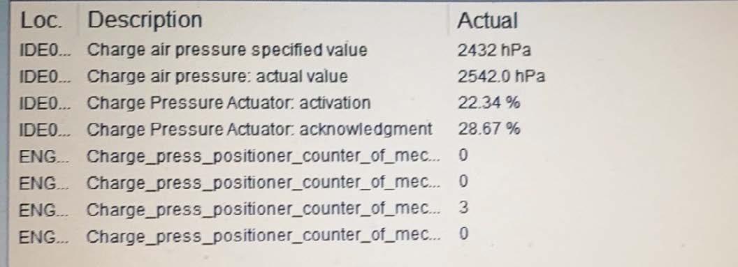
I carried out a quick road test and no found no limp mode and the van pulled strongly in all gears. Checking the live data, I found the boost values to be slightly out of tolerance under full load in third gear. I carried out a slight adjustment to the actuator (the threaded bar section) and rerun the road test. I know found a close tolerance (less than 300mbar eqv difference) between actual and desired, so as not to cause an under or over boost fault.
That’s not what I expected…
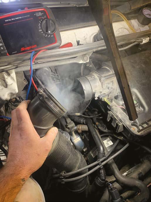
Wanting to belt and braces the job, I attempted to pull a vacuum on the reservoir itself – I was unable to. One step further saw me smoke test the reservoir. However, expecting to see smoke arise around the reservoir, I didn’t see any. Instead, I had smoke coming back through the airbox. Removing the intake pipe showed that the leak was in fact across the reservoir and through the PCV (Positive Crank Ventilation) and back through the inlet. The PCV on this model is also built
into the rocker cover assembly. In a broad and vast brand experience, I have changed many of these for failing and pooling oil around the fuel injectors, but never for this fault.
Everyday is a school day in this job, but we ended up with a positive diagnostic result, and the customer was happy to affect the necessary repairs themselves for their customer. I think despite whatever experience we have in terms of brand or known faults within a vehicle brand or model, there is always another fault waiting around the corner to adjust your outlook. The impossible is always possible…
Gareth Davies, Managing Director, Euro Performance Ltd, IMI Master Technician CAE AMIMI.