7 minute read
Ignition & engine management

Diagnosing makes life easier
While it is not the best of ideas to renew engine electrical components without prior investigation, some parts are fairly tiresome to remove, leading Rob Marshall to quiz NGK further about non-invasive diagnosis methods
Advertisement
Adopting a detective role within the cost and time pressures of a workshop environment is not always easy. While replacing parts blindly may yield a solution if you are lucky, it is quite different to substitute a known good component temporarily as part of a logical diagnostic process – a technique that many experienced technicians (and even technical trainers) advocate. However, not all components are that easy to access, meaning that extracting it needlessly could complicate the task if you run into trouble. So, what can you do?
Save time, by checking a component before removing it: this feature examines how to diagnose spark and glow plugs, plus exhaust gas temperature and O2 sensors

Spark Plugs
While we admit that there are some exceptions, spark plugs tend to be fairly accessible, which means taking them out is not necessarily going to present a major difficulty. Once removed, a visual examination will allow you to deduce if something is awry. Most problems are caused by the plug being affected by the failure of another component. Excessive fouling, therefore, can be the result of a neighbouring problem that may not be cured by cleaning the plug. Yet, it is true that fouling causes misfires, by preventing the spark from jumping between the two electrodes. This can result from excessive carbon build, caused by an engine running in too a rich a condition, or the plug nose being coated with oil, due to a mechanical problem. Yet, this is not to say that spark plugs can never fail, or that they are everlasting.
With the plug removed, inspect the plug insulator closely for cracks, which will cause a misfire, due to the voltage not being contained. A crack in the insulator on the firing end is usually caused by ‘thermal shock’, the result of neat, or poorly atomised, fuel hitting the hot insulator surface, causing it to cool rapidly, which may indicate a fuel injector fault.
Black vertical electrical lines on the white insulator surface (sometimes mistaken for cracks) are a sign of ‘flashover’. They can also strike between the top terminal and the metal shell body. Deteriorated plug rubber sealing boot(s) on the lead, or the ignition coil, tend to be responsible. Replacing the plug alone may not solve the problem, unless you ensure that the plug connection is secure and the seal over the insulator is effective.
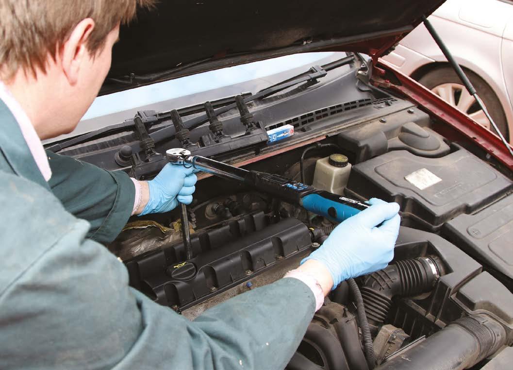
Unfortunately, technicians can be responsible for spark plug issues. An insulator that has cracked on its uppermost section tends to be from either over-tightening, or the plug being manipulated with the socket extension at an angle. This puts sideways pressure on the top of the plug, resulting in fractures. Should you discover a broken plug metal shell at the top of the thread, also suspect prior over-tightening. This advice emphasises the importance of following the recommended torque value, which differs depending on the plug thread size and sealing method (taper or gasket). Lubricating the threads is not recommended, due to it reducing the torque. On GDI engines especially, running problems result from not following the tightening angle advice, which ensures that the spark plug electrodes and injectors are aligned correctly for optimum combustion and emissions.
Glow Plugs
Compared with spark plugs, glow plugs tend not to be as accessible but they still should be considered as a service item. However, they are more prone to snapping, a situation that makes removal considerably more complicated. While higher compressions and direct injection mean that glow plugs are not as critical to cold-start performance as they once were, they play greater roles in other areas, especially suppressing emissions. For instance, glow plug issues tend to cause an active DPF regeneration to abort. In that situation, the problem rests not with the clogged particulate filter (which will require attention nonetheless) but with the glow plug circuit.
Clearly, glow plugs lead a harsh life but you can test them in situ, not least by checking the heater coil resistance, by removing the electrical lead and using a multimeter between the now uncovered top terminal and the cylinder-head. NGK advises that resistance values are not the same for all glow plugs and you will need to compare the result with the values specified for that part number. Where you do not know the brand of glow plug fitted, if you obtain a reading lower than five Ohms for a metal-type glow plug, it is safe to presume that it is serviceable. No reading indicates a broken heater coil. While this may result from natural wear and tear, a problem with the glow plug circuit could be responsible. For instance, it could be switching the plugs on for too long, or applying an excessive voltage.
Should you decide to undertake the delicate task of glow plug removal, pay particular attention to the heater tube surface, once the plug is extracted. Scuffs, or swirl marks indicate carbon build, which causes the plug to overheat and courts premature failure. It is also best practice not to replace a single faulty plug but a car set.

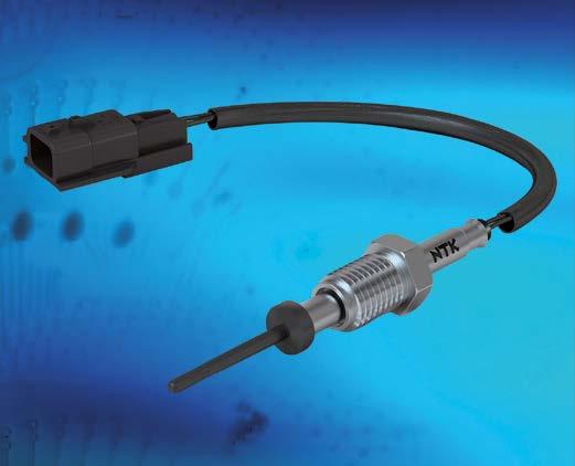
Exhaust Gas Temperature Sensors (EGT)
Many vehicles possess more than one EGT sensor. Therefore, when looking at fault codes, ensure that you are pinpointing the correct sensor for further inspection, diagnosis or replacement. Manual diagnostics is possible, by measuring the resistance between the two wires at room temperature and comparing them against the values provided by the OEM, or component manufacturer. Yet, consider that EGT sensors can be either one of two types: PCT (positive temperature coefficient, where the internal resistance rises as the sensor is heated) or NTC (negative temperature coefficient, where the resistance falls).
Once removed, the sensor operation can be observed, by observing the resistance change, with the sensor clamped in a vice and its probe being warmed with a heat gun. You can use either a multimeter, or an oscilloscope for this.
Lambda/O2 sensors
It is easy to forget that O2 sensors also wear gradually and do not always fail suddenly. The rate of deterioration is accelerated notably by poor quality oils and fuel that become deposited on the sensor element. The sensor can also be damaged irreparably by coolant entering the combustion chamber. All of these issues cause reduced control of the engine fueling, resulting in reduced MPGs, uneven running conditions and poor performance. Yet, most failures are identified at MOT test time, by a failed emissions test, and/or even a simple illuminated MIL. Yet, the formal emissions test lambda value is calculated, not measured. Therefore, a failed lambda result is not necessarily indicative of a failed sensor – a holed exhaust downstream of the sensor might be responsible, for example.
The tough environment in which the O2 sensor resides does not facilitate easy removal, especially on vehicles where access is tight. Thankfully, you do not need to extract it from the exhaust to check its function, which NGK recommends every 20,000 miles, or annually. The company reasons that an oscilloscope and gas analyser provides the most accurate way of assessing sensor performance and technicians can perform this task fairly quickly by looking for slow response times and output ranges.
Be extra vigilant should you discover that a vehicle possesses a non-OEM sensor... a potential for mismatch with the vehicle's system, or premature failure, is very high"
readings is possible in theory, provided that there is sufficient access. Trace the sensor wiring back to the wiring loom connector, making checks not just for damaged cabling but also for residue. It should be dry.
Very often, the O2 sensor heater circuit is powered via two white wires on four-wire Zirconia sensors, or those coloured white and grey on five-wire wideband sensors (as pictured below) but it is worth double-checking the vehicle's wiring diagram, because this is not a fixed rule. As per our earlier advice, unless the heater coil is broken, resistance values are not universal and so comparing your measurements against credible data sources is the best strategy.
Be extra vigilant, should you discover that the vehicle possesses a non-OEM sensor. NGK reports that universal sensors are designed to fit as many vehicles as possible, by splicing in the electrical connector from the unit being replaced. Theoretically, one would imagine that they offer an ideal solution but, in reality, NGK argues that a potential for mismatch with the vehicle's system, or subsequent premature failure, is very high. Logically, the company adds that a new O2 sensor should be installed, wherever a replacement catalytic converter is fitted.


