ASME B31.1-2014
(14)
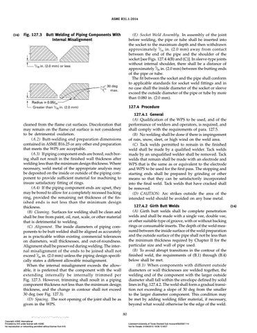
Fig. 127.3 Butt Welding of Piping Components With Internal Misalignment
1/ in. 16
(E) Socket Weld Assembly. In assembly of the joint before welding, the pipe or tube shall be inserted into the socket to the maximum depth and then withdrawn approximately 1⁄16 in. (2.0 mm) away from contact between the end of the pipe and the shoulder of the socket [see Figs. 127.4.4(B) and (C)]. In sleeve-type joints without internal shoulder, there shall be a distance of approximately 1⁄16 in. (2.0 mm) between the butting ends of the pipe or tube. The fit between the socket and the pipe shall conform to applicable standards for socket weld fittings and in no case shall the inside diameter of the socket or sleeve exceed the outside diameter of the pipe or tube by more than 0.080 in. (2.0 mm).
(2.0 mm) or less
30 deg max. Radius ⱖ 0.05tm Greater than 1/16 in. (2.0 mm)
127.4 Procedure 127.4.1 General (A) Qualification of the WPS to be used, and of the performance of welders and operators, is required, and shall comply with the requirements of para. 127.5. (B) No welding shall be done if there is impingement of rain, snow, sleet, or high wind on the weld area. (C) Tack welds permitted to remain in the finished weld shall be made by a qualified welder. Tack welds made by an unqualified welder shall be removed. Tack welds that remain shall be made with an electrode and WPS that is the same as or equivalent to the electrode and WPS to be used for the first pass. The stopping and starting ends shall be prepared by grinding or other means so that they can be satisfactorily incorporated into the final weld. Tack welds that have cracked shall be removed. (D) CAUTION: Arc strikes outside the area of the intended weld should be avoided on any base metal.
cleaned from the flame cut surfaces. Discoloration that may remain on the flame cut surface is not considered to be detrimental oxidation. (A.2) Butt-welding end preparation dimensions contained in ASME B16.25 or any other end preparation that meets the WPS are acceptable. (A.3) If piping component ends are bored, such boring shall not result in the finished wall thickness after welding less than the minimum design thickness. Where necessary, weld metal of the appropriate analysis may be deposited on the inside or outside of the piping component to provide sufficient material for machining to insure satisfactory fitting of rings. (A.4) If the piping component ends are upset, they may be bored to allow for a completely recessed backing ring, provided the remaining net thickness of the finished ends is not less than the minimum design thickness. (B) Cleaning. Surfaces for welding shall be clean and shall be free from paint, oil, rust, scale, or other material that is detrimental to welding. (C) Alignment. The inside diameters of piping components to be butt welded shall be aligned as accurately as is practicable within existing commercial tolerances on diameters, wall thicknesses, and out-of-roundness. Alignment shall be preserved during welding. The internal misalignment of the ends to be joined shall not exceed 1⁄16 in. (2.0 mm) unless the piping design specifically states a different allowable misalignment. When the internal misalignment exceeds the allowable, it is preferred that the component with the wall extending internally be internally trimmed per Fig. 127.3. However, trimming shall result in a piping component thickness not less than the minimum design thickness, and the change in contour shall not exceed 30 deg (see Fig. 127.3). (D) Spacing. The root opening of the joint shall be as given in the WPS.
127.4.2 Girth Butt Welds (A) Girth butt welds shall be complete penetration welds and shall be made with a single vee, double vee, or other suitable type of groove, with or without backing rings or consumable inserts. The depth of the weld measured between the inside surface of the weld preparation and the outside surface of the pipe shall not be less than the minimum thickness required by Chapter II for the particular size and wall of pipe used. (B) To avoid abrupt transitions in the contour of the finished weld, the requirements of (B.1) through (B.4) below shall be met. (B.1) When components with different outside diameters or wall thicknesses are welded together, the welding end of the component with the larger outside diameter shall fall within the envelope defined by solid lines in Fig. 127.4.2. The weld shall form a gradual transition not exceeding a slope of 30 deg from the smaller to the larger diameter component. This condition may be met by adding welding filler material, if necessary, beyond what would otherwise be the edge of the weld. 80
--``,`,`,,,``,,`,,`,``,`````,,,-`-`,,`,,`,`,,`---
Copyright ASME International Provided by IHS under license with ASME No reproduction or networking permitted without license from IHS
Licensee=University of Texas Revised Sub Account/5620001114 Not for Resale, 01/04/2015 19:08:13 MST
(14)