PRODUCT FOCUS
AutoCAD Civil 3D 2018 C. Once the block is in your file and pointing to the object, you can now edit the block to fill in the value with a field (Figure 5): 4. Right click in the attribute editor window. 5. Select objects in the Field Category column. 6. Select object. 7. Select the marker to select the “delete” line in your file. 8. Select length. 9. Select desired units. 10. Select desired precision.
DATAEXTRACTION FOR QUANTITIES I have to admit that the DATAEXTRACTION command seemed very intimidating at first. I spent a great amounts of time watching videos, reading blogs, and attempting to make it work. I finally decided one day to just buckle up and dive in. I am glad I did! I ended up creating a new workflow for my roadway design group that has saved many hours of manual counting and measuring. For this nugget, I will have you start a new drawing, draw some closed polyline shapes, draw a few lines, and insert a couple of blocks. Let’s keep our first try simple… Do the following: 1. Start a new drawing using acad.dwt. 2. Make a few layers (see Figure 7). 3. Insert some tree blocks and mailbox blocks. 4. Draw the stripe lines. 5. And lastly, draw a couple of closed polylines. 6. Take a deep breath and type DATAEXTRACTION. 7. Select Create a new data extraction, then hit Next.
Figure 5
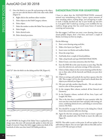
Add “LF” after the field is in the dialog and hit OK (Figure 6).
8. Save the DXE file to the same location as your dwg. This file saves the selection set, and some settings of this extraction. 9. Click on Select objects in the current drawing and hit the button to then select all the linework and blocks you just drew (Figure 8). 10. Click on settings and uncheck the top three squares, then hit OK. This is page 3 of 8 in the wizard and it should show the objects you selected (see Figure 8). 11. Hit next and take another deep breath… We are only interested in a few of these properties. 12. In the category filter column, uncheck all but General and Geometry. 13. In the Property column, uncheck all but Area, Layer, and Length. Hit Next. 14. This is the data that is available for your quantity table, hit next now, but come back here later and play with sorting columns, combining identical rows, and linking to external data sources. Hit Next. 15. You should be on page 6 of 8 now in the dialog box. Check Insert data extraction table into drawing.
Figure 6
IF and WHEN the length of the “delete” line is updated by your design team, this note will automatically update to show the new length of removal. I hope this little nugget makes you think of the hundreds of other uses that AutoCAD fields provide us.
22
www.augi.com
16. Again for this first attempt, just hit Next to insert a generic table with standard style. Hit Finish to insert the table (see Figure 9). NOTE: This table is static at this point. It will not update if you add/subtract objects. You can now right-click on this table and export to a CSV file and open in Excel.
March 2018