MEP Hidden Line Display
A COMPLETE MODEL?
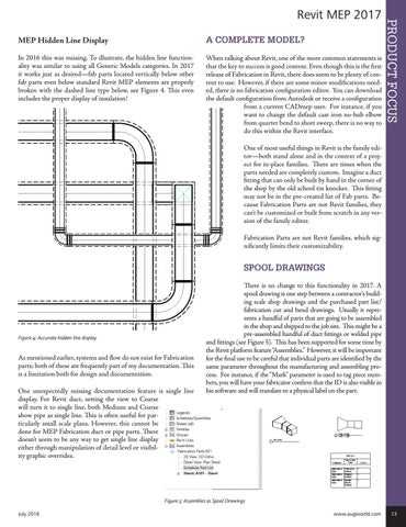
In 2016 this was missing. To illustrate, the hidden line functionality was similar to using all Generic Models categories. In 2017 it works just as desired—fab parts located vertically below other fab parts even below standard Revit MEP elements are properly broken with the dashed line type below, see Figure 4. This even includes the proper display of insulation!
When talking about Revit, one of the more common statements is that the key to success is good content. Even though this is the first release of Fabrication in Revit, there does seem to be plenty of content to use. However, if there are some minor modifications needed, there is no fabrication configuration editor. You can download the default configuration from Autodesk or receive a configuration from a current CADmep user. For instance, if you want to change the default cast iron no-hub elbow from quarter bend to short sweep, there is no way to do this within the Revit interface.
PRODUCT FOCUS
Revit MEP 2017
One of most useful things in Revit is the family editor—both stand alone and in the context of a project for in-place families. There are times when the parts needed are completely custom. Imagine a duct fitting that can only be built by hand in the corner of the shop by the old school tin knocker. This fitting may not be in the pre-created list of Fab parts. Because Fabrication Parts are not Revit families, they can’t be customized or built from scratch in any version of the family editor. Fabrication Parts are not Revit families, which significantly limits their customizability.
SPOOL DRAWINGS
Figure 4: Accurate hidden line display
As mentioned earlier, systems and flow do not exist for Fabrication parts; both of these are frequently part of my documentation. This is a limitation both for design and documentation. One unexpectedly missing documentation feature is single line display. For Revit duct, setting the view to Coarse will turn it to single line, both Medium and Coarse show pipe as single line. This is often useful for particularly small scale plans. However, this cannot be done for MEP Fabrication duct or pipe parts. There doesn’t seem to be any way to get single line display either through manipulation of detail level or visibility graphic overrides.
There is no change to this functionality in 2017. A spool drawing is one step between a contractor’s building scale shop drawings and the purchased part list/ fabrication cut and bend drawings. Usually it represents a handful of parts that are going to be assembled in the shop and shipped to the job site. This might be a pre-assembled handful of duct fittings or welded pipe and fittings (see Figure 5). This has been supported for some time by the Revit platform feature “Assemblies.” However, it will be important for the final use to be careful that individual parts are identified by the same parameter throughout the manufacturing and assembling process. For instance, if the “Mark” parameter is used to tag piece numbers, you will have your fabricator confirm that the ID is also visible in his software and will translate to a physical label on the part.
Figure 5: Assembles as Spool Drawings July 2016
www.augiworld.com 13