It’s now very easy to see that the fill volume represents the berm on the south side of the basin. To finish the exhibit, use the Draworder command to push the Volume Calcs surface to the back of the drawing and you’re ready to send it to the printer. The best part about this analysis is that it’s completely dynamic. If the existing or proposed conditions change, the volume calculations, and the colorized shading will update automatically. (Note: The Volume Calcs surface may need to be updated using the “ Rebuild” option to see the changes.)
CREATING A STYLE TO LABEL CUT/FILL MEASUREMENTS Another way we can bring our earthwork calculations to life is by adding a series of spot elevations that represent cut-fill measurements. While this seems like it might be a time-consuming task, Civil 3D does most of the work for us. Before we get started, we need to create a label style. Step 1: On the Settings tab of the Toolspace, expand the Surface group followed by the Label Styles group. Step 2: Rightclick on the Spot Elevation heading and select New to open the Label Style Composer. Step 3: Select the Information tab and name the style “Cut-Fill Labels.” Step 4: Select the General tab and use the Label Layer setting to select an appropriate layer name for the labels. (Example – volume lbls). Step 5: Select the Layout tab, choose an appropriate Text Height, and set the Anchor Point and the Attachment settings to “Middle Center” (see Figure 8).
AutoCAD
Civil 3D 2010 and 2011
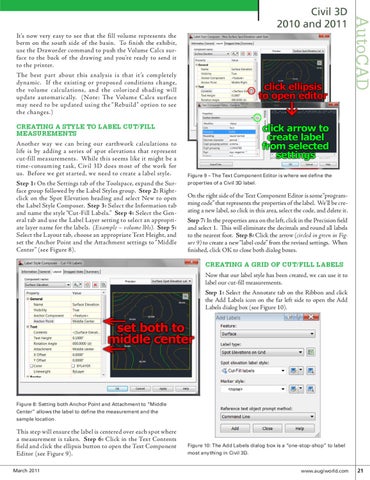
Figure 9 – The Text Component Editor is where we define the properties of a Civil 3D label.
On the right side of the Text Component Editor is some “programming code” that represents the properties of the label. We’ll be creating a new label, so click in this area, select the code, and delete it. Step 7: In the properties area on the left, click in the Precision field and select 1. This will eliminate the decimals and round all labels to the nearest foot. Step 8: Click the arrow (circled in green in Figure 9) to create a new “label code” from the revised settings. When finished, click OK to close both dialog boxes.
CREATING A GRID OF CUT/FILL LABELS Now that our label style has been created, we can use it to label our cut-fill measurements. Step 1: Select the Annotate tab on the Ribbon and click the Add Labels icon on the far left side to open the Add Labels dialog box (see Figure 10).
Figure 8: Setting both Anchor Point and Attachment to “Middle Center” allows the label to define the measurement and the sample location.
This step will ensure the label is centered over each spot where a measurement is taken. Step 6: Click in the Text Contents field and click the ellipsis button to open the Text Component Editor (see Figure 9). March 2011
Figure 10: The Add Labels dialog box is a “one-stop-shop” to label most anything in Civil 3D.
www.augiworld.com 21