CREATING A TIN VOLUME SURFACE Fortunately, Civil 3D has several tools for calculating the volume between two surfaces. In this example, since we’d like our cut and fill information displayed graphically, we’ll use a TIN volume surface to do the calculations. A TIN volume surface is a surface whose elevations are determined by the “differences” in elevation between a pair of surfaces. Let’s get started… Step 1: Right-click on the Surfaces heading inside Prospector and select Create Surface. Step 2: In the Create Surface dialog box, open the Type: menu and choose TIN volume surface. Step 3: Click in the Name field and call the surface “Volume Calcs.” (Next we’ll select the two surfaces we’d like to compare.) Step 4: Click in the Base Surface field and select the surface representing existing conditions. (In my case, I selected EXTP.) Step 5: For the Comparison Surface, choose the surface representing proposed conditions. (I selected PRTP.) Note the optional Cut and Fill factors to compensate for expansion or compaction of material. When finished, compare your settings to the ones shown in Figure 2.
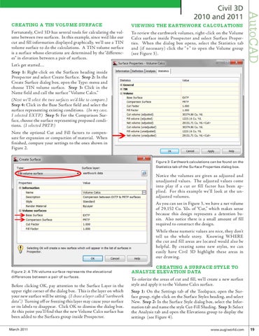
VIEWING THE EARTHWORK CALCULATIONS To review the earthwork volumes, right-click on the Volume Calcs surface inside Prospector and select Surface Properties. When the dialog box opens, select the Statistics tab and (if necessary) click the “+” to open the Volume group (see Figure 3).
AutoCAD
Civil 3D 2010 and 2011
Figure 3: Earthwork calculations can be found on the Statistics tab of the Surface Properties dialog box.
Notice the volumes are given as adjusted and unadjusted values. The adjusted values come into play if a cut or fill factor has been applied. For this example we’ll look at the unadjusted volumes. As you can see in Figure 3, we have a net volume of 29,152 Cu. Yds. of “Cut,” which makes sense because this design represents a detention basin. Also notice there is a small amount of fill required to construct the design. While these numeric values are nice, they don’t tell us the whole story. Knowing WHERE the cut and fill areas are located would also be helpful. By creating some new styles, we can easily have Civil 3D highlight these areas in our drawing. Figure 2: A TIN volume surface represents the elevational differences between a pair of surfaces.
Before clicking OK, pay attention to the Surface Layer in the upper right corner of the dialog box. This is the layer on which your new surface will be sitting. (I chose a layer called “earthwork data”.) Turning off or freezing this layer may cause your surface or its labels to disappear. Click OK to dismiss the dialog box. At this point you’ll find that the new Volume Calcs surface has been added to the Surfaces group inside Prospector. March 2011
CREATING A SURFACE STYLE TO ANALYZE ELEVATION DATA To colorize the areas of cut and fill, we’ll create a new surface style and apply it to the Volume Calcs surface. Step 1: On the Settings tab of the Toolspace, open the Surface group, right-click on the Surface Styles heading, and select New. Step 2: In the Surface Style dialog box, select the Information tab and name the style Cut-Fill Shading. Step 3: Select the Analysis tab and open the Elevations group to display the settings (see Figure 4).
www.augiworld.com 19