feature focus
MEP Calculating GPM and Sizing Hydronic Pipe The GPMs are entered into the terminal units using a simple information schedule (see Figure 2). Revit MEP calculates the GPM all the way through the pipe back to the mechanical room. You can click on a pipe anywhere in the system and see the calculated GPM (see Figure 3). If a GPM changes on a unit, you can go to the schedule and change the flow. Then go back to the model, view the calculated GPM, and change the size if necessary.
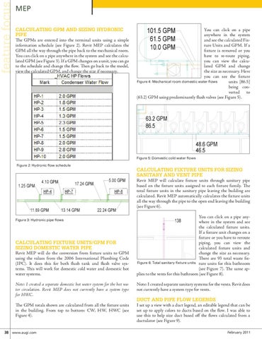
You can click on a pipe anywhere in the system and see the calculated Fixture Units and GPM. If a fixture is removed or you have to re-route piping, you can view the calculated GPM and change the size as necessary. Here you can see the fixture Figure 4: Mechanical room domestic water flows units [86.5] being converted to (63.2) GPM using predominantly flush valves (see Figure 5).
Figure 5: Domestic cold water flows Figure 2: Hydronic flow schedule
Calculating Fixture Units for Sizing Sanitary and Vent Pipe Revit MEP will calculate fixture units through sanitary pipe based on the fixture units assigned to each fixture family. The total fixture units in the sanitary pipe leaving the building are calculated. Revit MEP automatically calculates the fixture units all the way through the pipe to the open end leaving the building (see Figure 6).
Figure 3: Hydronic pipe flows
Calculating Fixture Units/GPM for Sizing Domestic Water Pipe Revit MEP will do the conversion from fixture units to GPM using the values from the 2006 International Plumbing Code (IPC). It does this for both flush tank and flush valve systems. This will work for domestic cold water and domestic hot water systems. Note: I created a separate domestic hot water system for the hot water circulation. Revit MEP does not currently have a system type for HWC. The GPM totals shown are calculated from all the fixture units in the building. From top to bottom: CW, HW, HWC (see Figure 4).
38 www.augi.com
You can click on a pipe anywhere in the system and see the calculated fixture units. If a fixture unit changes on a fixture or you have to reroute piping, you can view the calculated fixture units and change the size as necessary. There are 93 total waste fixFigure 6: Total sanitary fixture units ture units for this bathroom (see Figure 7). The same applies to the vents for this bathroom (see Figure 8). Note: I created separate sanitary systems for the vents. Revit does not currently have a system type for vents.
Duct and Pipe Flow Legends I set up a view with a duct legend, an editable legend that can be set up to apply colors to ducts based on the flow. I was able to use this to help size duct based off the flows calculated from a ductulator (see Figure 9). February 2011