MEP
Calculating Flows For Sizing Duct and Pipe
O
ver the course of my last few Autodesk® Revit® MEP projects, I have been able to use the information in the models to calculate flows, which has assisted with sizing of duct and pipe. This has made the process more productive and eliminates the need to calculate everything on paper. In addition, it has made it easier to adapt to changes as the design process evolves. While this works well on simple projects, it can get challenging when applying it to more complex designs. In this article, I intend to show the capabilities of using Revit MEP for these calculations.
➲
How it works Revit MEP is doing these calculations based off the properties in the duct and pipe connectors within the families. The connectors have system type properties for supply air, return air, exhaust air, hydronic supply, hydronic return, domestic cold water, domestic hot water, and sanitary systems. Depending on the system type and flow stream, the connectors are set up in different ways to calculate CFM, Fixture Units, and GPM.
• • • •
feature focus
by: Phil Pleiss
Sanitary and vent systems need to have one open end. The open end is typically the pipe leaving the building. Creating information schedules has been a great way to manage the parameters in the families. Some scenarios need to be calculated manually. For example, complex duct and piping in a mechanical room. These systems have proven to be accurate and easy to troubleshoot. For example, if you click on a duct or a pipe and the flow is 0 that means something is not connected or there is an opening in the system somewhere.
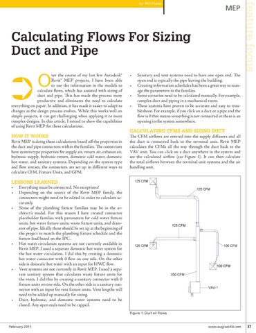
Calculating CFMs and Sizing Duct The CFM airflows are entered into the supply diffusers and all the duct is connected back to the terminal unit. Revit MEP calculates the CFMs all the way through the duct back to the VAV unit. You can click on a duct anywhere in the system and see the calculated airflow (see Figure 1). It can then calculate the total airflows between the terminal unit systems and the air handling unit.
Lessons learned • Everything must be connected. No exceptions! • Depending on the source of the Revit MEP family, the connectors might need to be edited in order to calculate accurately. • Some of the plumbing fixture families may be in the architect’s model. For this reason I have created connector placeholder families with parameters for cold water fixture units, hot water fixture units, waste fixture units, and diameter of pipe. Ideally these should be set up at the beginning of the project to match the plumbing fixture schedule and the fixture load based on the IPC. • Hot water circulation systems are not currently available in Revit MEP. I used a separate domestic hot water system for the hot water circulation. I did this by creating a domestic hot water connector with 0 flow on one side. On the other side is domestic hot water with an input for HWC flow. • Vent systems are not currently in Revit MEP. I used a separate sanitary system that calculates waste fixture units for the vents. I did this by creating a sanitary connector with 0 fixture units on one side. On the other side is a sanitary connector with an input for vent fixture units. Vent lengths will need to be added up manually for sizing. • Duct, hydronic, and domestic water systems need to be closed. Any open ends need to be capped. Figure 1: Duct air flows
February 2011
www.augiworld.com 37