feature focus
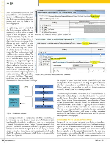
MEP arate models to the contractor. Each project has the same files linked into it, so we could just accept the respective design options in the discipline projects and bind the links in the building projects. To split it up, first we created all the design options within the one project file we had, then we made copies of that one project. For the Figure 3: V/G control of Design Options in same file discipline-specific projects, we deleted the worksets not pertinent to that trade (thereby removing all the objects no longer needed in that project). Then we made a copy for each of the buildings and deleted all of the discipline worksets from it as well. Then we interlinked each working project into the others. The discipline projects then needed to be linked into the sheets projects. See the linked file diagram in Figure 2. We keep the buildings separate at the sheets level so that when we turn the project over to the owner, we can bind each link, with the design options for that building set to primary within the linked file, and deliver Figure 4: V/G control of Design Options in linked file six separate buildings. These easily could have been one sheet files, with the same views for the different buildings. Be prepared to spend some time on this, particularly if you have multiple files. View templates do not help this process because they have only one button for all RVT Links, not per RVT Link. Either make one view template per level, per design option, or manually set each view to each design option.
Figure 2: Linked file diagram
Some important notes to realize about all of this interlinking is how to assign a specific design option to a view. While the project is still one file, the visibility graphics, per view, can be set to show a specific design option. Once Design Options is enabled for a project, a new tab is available under visibility graphics properties for each view as shown in Figure 3. If you are trying to show a design option for a linked file, as we were doing, then look under the RVT Links tab to make select which design option should be shown (see Figure 4). 34 www.augi.com
Another complication that arises from all of these linked files is the need to make a change to a file that is linked into your current model. Revit will not allow having a linked file open at the same time. To get around this you can open a second session of Revit (Note: it does not take a second license) and within that session open the linked file. But don’t try to copy objects between the two sessions as that can only be done within the same session. (Tip: You can open a file detached from central in the same session and copy if needed) The only other trick would be to have a workset dedicated to your linked files. If you unload that workset, you can then open the linked project.
Systems with Design Options In general, yes, you can use systems in your design options; however, there are some unfortunate limitations. Families in a design option will not be able to connect to systems not in the same option. A good example is any room that is an option will need to have receptacles in it. The electrical connector for the receptacle in the design option will not be able to connect to the electrical panel that is in the primary design. However, you can create new February 2011