MEP
Design Options with Revit MEP
➲
F
or those who are not familiar with the Design Options tool in Autodesk® Revit®, understand that it is intended to illustrate options to a primary design. My grandfather used to say, “There are enough ways in the world for each to have his own.” Well, this tool is a way to explore the different ways to solve a problem. Then the different solutions can be evaluated to determine which one is best. A simple example would be a house with a covered porch or a wraparound porch. The porch design is an option to the house (aka, the primary design). Once a choice is made, that option can be accepted within Revit and it becomes part of the primary design. Design Options allows designers to provide choices to the decision makers, and integrate those choices into the model.
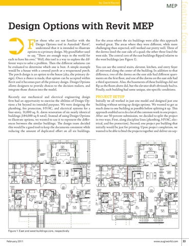
You can see the central stairs, elevator, kitchen, and entry foyer all mirrored along the center of the building. In addition to that difference, two of the dorms on the eest side had different apartments on the first floor, and one of the dorms on the east side had a third apartment. Also, the basements of these buildings did not flip as the floors above did, but the elevator shaft obviously had to. Finally, each building had some unique, site-specific conditions.
Recently our mechanical and electrical engineering design firm had an opportunity to exercise the abilities of Design Options a bit beyond its intended purpose. We were designing the plumbing, fire protection, HVAC, and electrical systems for a four-story, 31,000 sq. ft. dorm renovation of six nearly identical buildings (184,000 sq ft total). Instead of using Design Options to illustrate options, we wanted to use it to represent the differences between the similar buildings. The design team decided this would be a good tool to keep the documents consistent while reducing the amount of duplicated effort on all six buildings.
Project setup Initially we all worked in just one model and designed just one building without setting up design options. We wanted to get as much done to one building as possible before splitting it up. This approach enabled us to do a lot of the common work in one project. After our 50 percent submission, we decided to split the project in two ways. First, along discipline lines (plumbing, HVAC, electrical, and fire protection). Second, one project per building that initially would be just for printing. Upon project completion, we wanted to be able to bind the projects together and deliver six sep-
For the areas where the six buildings were alike this approach worked great. The areas where they were different, while more challenging than expected, still worked out pretty well. Three of the dorms lined the east side of a quad; the other three lined the west side. The central core of the east buildings flipped relative to the west buildings (see Figure 1).
feature focus
by: David Raynor
Figure 1: East and west buildings core, respectively
February 2011
www.augiworld.com 33