5 minute read
Products

from Modern Tire Dealer - September 2021
by EndeavorBusinessMedia-VehicleRepairGroup

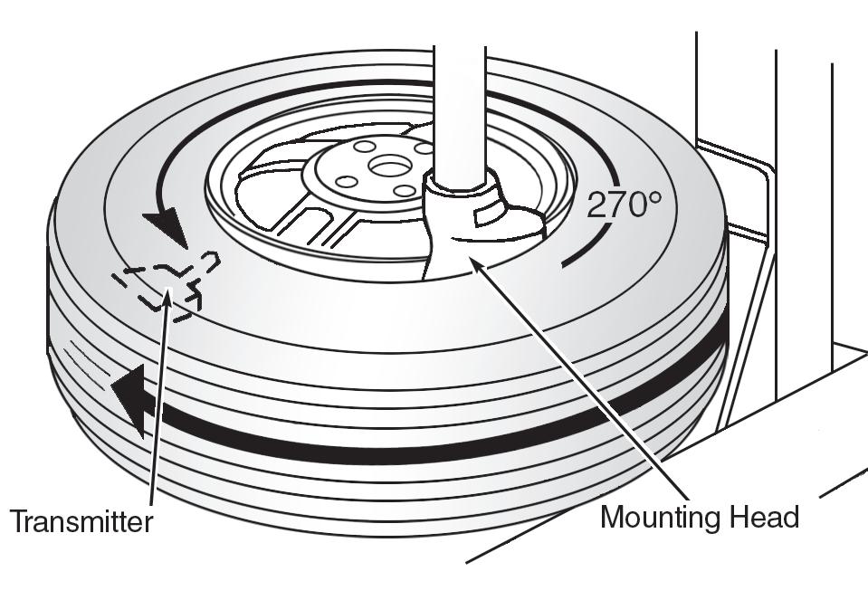
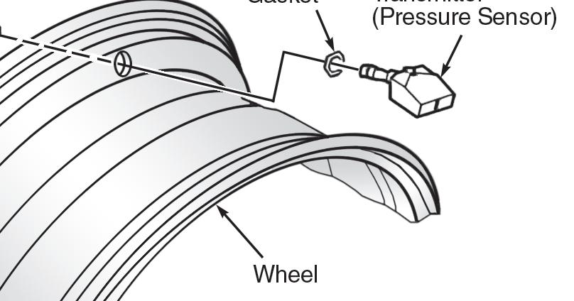
Figure 3: Positioning Tire On Turntable. Carefully lift the tire onto the turntable and position the valve hole and transmitter 270 degrees from the mounting/demounting head. Figure 4: Removing and Installing Tire Pressure Transmitter. Lubricate the tire well, and remove the top side of the tire. Reach inside the tire and remove the transmitter.
provided “asleep” and must rst be “woken up” using Transmitter Activation Tool J-45295 or Signal Tech II Tool J-50190 before ID registration can be performed. Use the following procedure when using the Transmitter Activation Tool J-45295:
1. With the ignition switch in the OFF position, connect the scan tool to the
DLC. Turn the ignition switch to the
ON position; 2. Display the “WORK SUPPORT” screen and select “ID REGIST;” 3. With the Transmitter Activation Tool (J-45295) pushed against the le front tire air-valve, press the button for

IS THE ONLY TPMS MANUFACTURER TO OFFER A
COMPLETE SOLUTION
OE QUALITY SENSORS POWERFUL SCAN TOOLS
UPDATES POWERED BY DIAGNOSTICS
ALUMINUM OR RUBBER VALVE STEMS AVAILABLE
1-SENSOR
• 1-SKU Limited Inventory • Dual Frequency 315MHz + 433MHz • 99% Vehicle Coverage • Interchangeable Valve Stems
TS508KMV-1
• Read/Relearn All Known Sensors • 4 MX-Sensor Programming Methods • FREE Software Updates for Life of Tool • Exclusive TPMS Status Screen
CONTACT YOUR AUTEL DISTRIBUTOR FOR MORE TPMS KIT OPTIONS
ve seconds. (See Figure 1.) Sensor activation must be performed in the order listed: le front, right front, right rear and le rear. As each sensor ID is activated, the TPMS warning light ashes is the pattern shown in Figure 2 and the scan tool indicator light changes from red to green; 4. Check that the turn signal lights blink twice when the transmitter wake-up procedure for all wheels is completed; 5. A er completing the wake up of all transmitters, make sure the TPMS warning light goes out.
DEMOUNTING/MOUNTING PROCEDURES
CAUTION: e tire should be demounted from the wheel using the tire changer manufacturer’s instructions. Use the following information to avoid damage during the demounting/mounting procedures. Also ensure there is no metalized film or any metal parts (antenna, etc.) on the windows, as this may cause poor reception of the signals from tire pressure sensors and the TPMS will not function properly.
NOTE: When a spare tire is mounted or a wheel or tire pressure sensor or low tire pressure warning control unit is replaced, the tire pressure sensor must be registered. See RESET PROCEDURES.
TIRE PRESSURE SENSOR
CAUTION: Do not inject any tire liquid or aerosol tire sealant into tires, as this may cause a malfunction of the tire pressure sensors.
Removal
1. De ate the tire. Unscrew the transmitter retaining nut and allow the transmitter to fall into tire; 2. Gently bounce the tire so that the transmitter falls to the bottom of the tire. Place the wheel and tire assembly on the tire changing machine and break both tire beads. Ensure that the transmitter remains at the bottom of the tire while breaking the bead; 3. Turn the tire so that the valve hole is at the bottom and gently bounce the tire to ensure the transmitter is near the valve hole. Carefully li the tire onto the turntable and position the valve hole and transmitter 270 degrees from the mounting/dismounting head. (See Figure 3); 4. Lubricate the tire well and remove the top side of the tire.
Reach inside the tire and remove the transmitter. (See
Figure 4.); 5. Remove the second side of the tire, as normal.
Installation
1. Place the rst side of the tire onto the wheel. NOTE: A er every disassembly, use a new seal; 2. Apply suitable silicone lubricant to the new seal, then install the seal on the sensor. Ensure that no burrs exist in the valve stem hole of the wheel; 3. Mount the transmitter on the rim and tighten nut to 61 to 72 inch-pounds (See Figure 4.) Do not touch the transmitter with the mounting head;
Component Wheel nut TORQUE SPECIFICATIONS
Ft.-lbs. (N.m)
83 (113)
INCH Lbs. (N.m)
Tire Pressure Sensor Nut 68 (7.7)
4. Place the wheel on the turntable of the tire machine. Ensure that the transmitter is 270 degrees from the mounting/ demounting head. (See Figure 3); 5. Lubricate the tire well and install the second side of the tire, as normal. Ensure that the tire does not rotate relative to the rim; 6. In ate the tire. Balance the wheel and tire assembly; 7. Install the wheel and tire assembly in appropriate wheel position on the vehicle; 8. Register the tire pressure sensor. (See RESET PROCEDURES.) ■
Information for this column comes from the tire pressure monitoring systems data in ProDemandR, Mitchell 1’s auto repair information software for domestic and import vehicles. Headquartered in Poway, Calif., Mitchell 1 has provided quality repair information solutions to the automotive industry since 1918. For more information, visit www. mitchell1.com. To read archived TPMS articles, visit www.moderntiredealer.com.


Single SKU Rubber Snap-In PN #33500
FEATURES AND BENEFITS
• All-weather, corrosion resistant rubber snap-in • Available with clamp-in silver and matte black aluminum stems • Performance sensor rated for 115 PSI • Rated for applications up to 130 MPH top speed
EZ-sensr
Family of Products
Visit SchraderTPMS.com to discover the full line!
Rubber Snap-In Part #33500 0° - 40° Adjustable Angle Aluminum Clamp-In Part #33700 90° Aluminum Clamp-In Part #33900