14 minute read
DIAGNOSING FAULTS IN HIGH SPEED COMMUNICATIONS

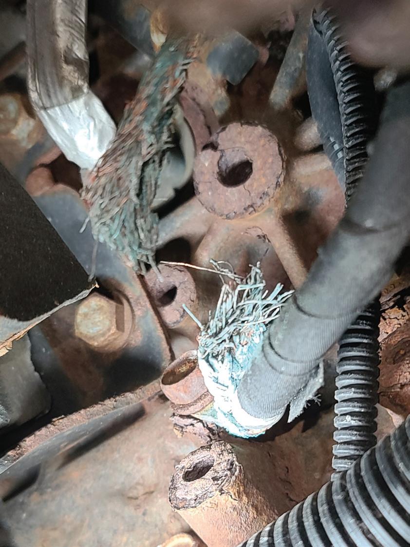
from Auto Service Professional - April 2021
by EndeavorBusinessMedia-VehicleRepairGroup

Fig. 23: Vehicles equipped with ABS may require very specific system bleeding procedures. Always refer to the OE service steps.
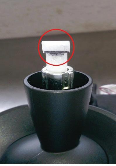
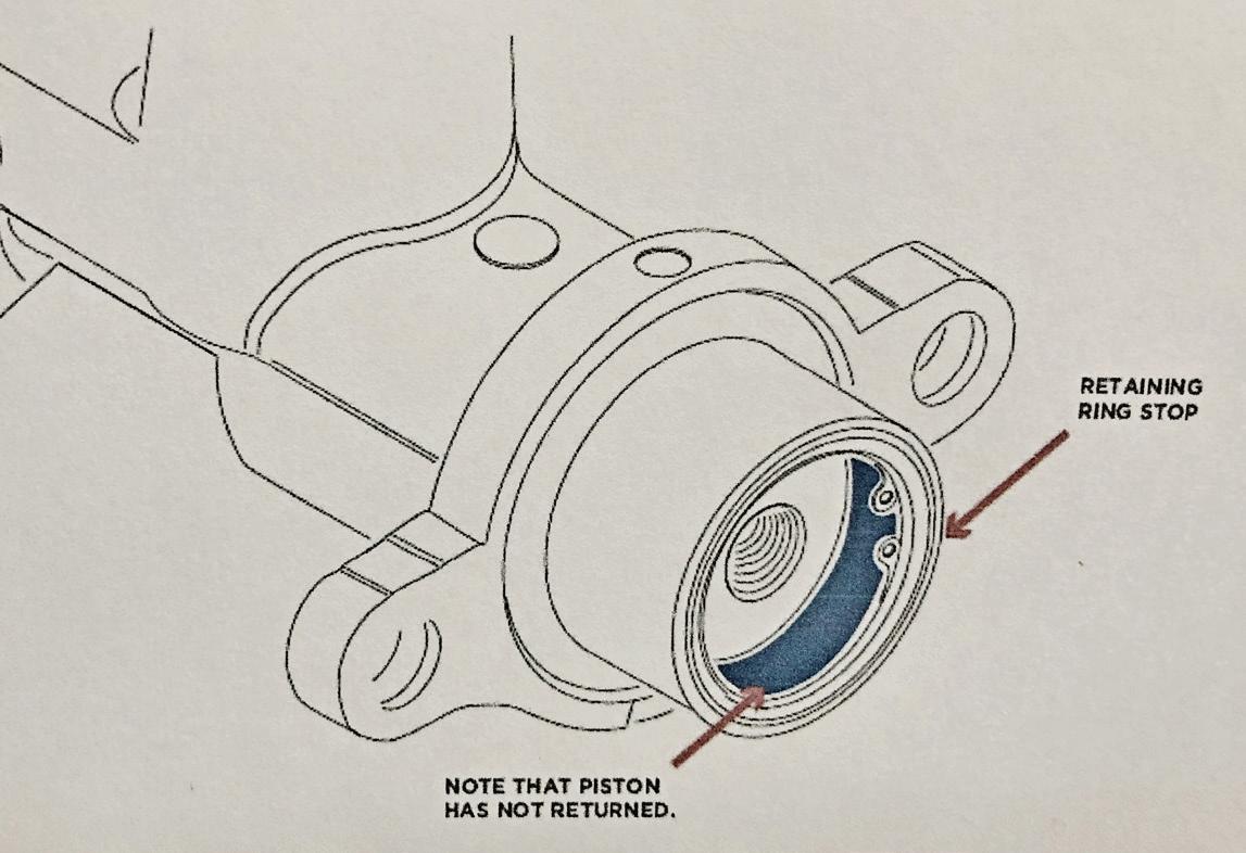
Fig. 24: If a new master cylinder piston does not fully return during bleeding, it may simply be temporarily stuck due to an internal vacuum lock. Use a pressure bleeder (with all wheel bleeders open) or lightly tap the cylinder housing to free the piston. Once the piston has returned to full rest against the rear snap ring, the issue should not recur. (image courtesy Wagner Brakes)
If you diagnose a bad hub bearing on one side of a vehicle and the ABS wheel speed sensor or tone ring is integral to the bearing, you may need additional repairs to restore proper ABS functioning. In many cases, replacing one hub bearing will cause the driver to feel ABS false activation when coming to a slow stop on dry pavement.
False activation is usually described as a pulse in the brake pedal when not expected. The pulsation comes from the ABS valves cycling the supposedly locked up wheel. This is due to the difference in signal strength from the wheel speed sensors (WSS) side to side. The problem is usually associated with air gap difference or wiring and/or connector integrity. In many cases, removing the WSS from the other side, if possible, and cleaning the mounting surface may repair the problem. The rust buildup actually lifts the WSS from the bearing, increasing the air gap and weakening the signal. Another possible issue is play in the bearing causing sine wave frequency change and or AC voltage variation. The new bearing will have little to no play, while the remaining hub has acceptable play but can still affect signal strength. Again, the difference in signal from side to side may be enough to trigger false activation. If WSS is integral and not serviceable, replacing the hub bearings in pairs may be the only answer. The ABS system is activating as designed, so no warning light will be illuminated in most cases.
If the ABS warning light is on, chances are the issue is with a bad wheel speed sensor or a ground. Check the grounds first (ground cables grounded at the frame) for cleanliness. If rusted/corroded, remove, clean and replace. Next, per your scan tool’s direction for a specific wheel speed sensor location, check the wheel speed sensor. Inspect the sensor connector. Remove the sensor from its location and clean the mounting area. Check the sensor magnet for contamination.
If the electronic brake control module (the ABS controller) is deemed faulty and requires replacement, after the lines have been disconnected and the unit removed, check and clean all line connectors. Make sure that threads are clean and that each connector freely rotates on the hard line. If rust/contaminants prevent free rotation, this can make reconnection difficult and can easily result in thread damaged and/or a fluid leak. After the new controller has been installed, the system must be bled, according to factory procedures. Always follow the specific procedure. Otherwise you may never bleed the system properly.
Our thanks to the following for their input in this article: Advics; Raybestos (Brake Parts Inc.); Wagner Brakes
Taking a methodical approach with the Controller Area Network
BY JEFF TAYLOR
ANY TECHNICIANS START TO FEEL
MUNCOMFORTABLE ABOUT a diagnostic situation if the scanner only shows U-codes, but if the scanner powers up but will not communicate, that uncomfortable feeling intensifies. Most techs are familiar with the multitude of communications networks used on today’s vehicles, but few are ever excited about diagnosing and repairing the most common network used today: Controller Area Network (CAN).
CAN is a serial communication bus that is tough and durable enough to perform well in the harsh environment of today’s automotive applications. Developed in 1984 by Bosch and Intel and first used in 1992, it has become the backbone for most of today’s vehicles’ high speed communications networks.
CAN bus diagnostics are often challenging but are no different from other forms of diagnostics. Attention to detail is important and understanding how the circuits work is vital.
CAN bus related complaints can cause a wide range of issues: warning lights, functionality issues, limited

Fig. 1
power mode, no transmission shifts, dead batteries, etc. The list of issues can be extensive.
A CAN bus allows for multiple modules to be linked together, reducing the amount and complexity of the vehicle’s wiring. The CAN bus provides the manufacturer the ability to plug in modules as required and each of these modules is then able to communicate with all the other modules on the same CAN bus.
Many of today’s vehicles will now have more than one CAN bus. There will be a high speed CAN bus for critical operations such as engine control, steering, brakes and other safety systems. But CAN is now used in many comfort, audio and interior control systems that previously used lower speed or manufacturer-specific network protocols. FCA (Fiat Chrysler Automobiles)/Ram uses a CAN bus called CAN IHS (CAN Interior High Speed). Honda, Toyota and others use a similar setup.
The CAN bus uses a twisted pair of wires; a CAN Hi wire and CAN Lo wire to join modules together in a loop or bus as it is commonly referred to. CAN modules communicate by varying the voltage on these two wires. The data is sent along the bus in digital bits of information as a 1=Hi and 0=Lo.
But twisted wires and modules are not the only pieces integral to a functioning CAN bus. There will also be two terminating resistors somewhere in the system, and testing for these resistors will aid in our diagnostics. Terminating resistors can be in a module, or they can be attached to the network remotely, but there will always be two. Service information or wiring diagrams will usually provide their location. BMW/Mercedes Benz often use remotely installed resistors and FCA puts theirs in their Star Connectors.
Each terminating resistor is 120 Ω, and its purpose is to absorb any of the leftover message voltage that occurs after the message has been read and received by all the modules on the CAN bus. Because there are two 120 Ω resistors wired in parallel, the actual resistance of the CAN bus will be 60 Ω (this is important to remember).
If one or both terminating resistors fails this may cause module communications issues, no scan tool communications and even a no-start. Terminating resistors are one of the first things to inspect when dealing with a CAN bus issue.
Testing a CAN system requires tools that most tech have at their disposal. An up-to-date scanner, a good information system to show the network wiring diagram, module locations, module powers, grounds and terminating resistor location. A digital volt-ohmmeter (DVOM), digital storage oscilloscope (DSO), and DLC breakout box will simplify testing.
Before testing for a CAN bus issue/failure, it is important to look at all the basics. These systems are sensi-
Fig. 1: This SRS module from under the seat of a GM was completely corroded and was stopping all communications on the CAN bus. The truck would still run and drive but the dash was lit up with warning lights.
Fig. 2: This broken chassis ground strap on a 2016 GM G van with a 6.6 diesel was the cause of 34 different U-codes. The van would start and run and communicate on the CAN bus. The SES, ABS light and Emission warning (DEF system) were illuminated, and the ABS data showed a module voltage of only 9 volts, all because of a bad ground.
Fig. 2
tive to proper module voltages and module grounds. A thorough visual inspection is key: the simplest things can cause the most complex issues and most challenging diagnostics. But many times, these complex issues can come down to a simple solution.
Bad grounds, poor battery voltage, poor connections, charging system issues, customer installed aftermarket devices and corrosion are some of the most common things that can cause CAN bus issues.
After performing a full system scan of all vehicle modules (if the scanner will communicate), pay particular attention to which modules are able to communicate and which ones are not. This may point you in a diagnostic direction. If you know that the vehicle has ABS, but the ABS module is not showing up in a full module scan, it would certainly be the starting point in the diagnostics. If the ABS light is on and there are U-codes in other modules telling you that they cannot talk to the ABS module, a few simple tests for power, ground and communication lines will likely confirm the fact the ABS module has failed.
The use of an OBDll breakout box can aid in initial testing. Although not absolutely needed, they are cheap and make pin testing of the CAN network much simpler, especially if you want to use a DSO, DVOM and a scanner simultaneously.
A few simple tests can be done at the DLC using just DVOM, or a DVOM and a DSO combination. They are quick and can easily help in pinpointing a problem by verifying the CAN bus circuit integrity or the lack thereof.
The following values are rules of thumb but if in doubt make sure to consult the vehicle’s manufacturer specifications. The pin numbers are for the standard wired OBDll compliant DLC.
Test #1... Resistance testing between pin 6 (CAN Hi) and pin 14 (CAN Lo) at the
DLC: to check the resistance of the CAN bus we need to disconnect the battery and allow a few minutes for all the power to dissipate from the modules. • The spec is 58 to 64 Ω. • If the resistance is 116 to 128 Ω, there is an open circuit, and you are measuring the resistance of only 1 terminating resistor. • If the meter displays OL there is an open
somewhere before the first terminating resistor. • If the resistance is 0 to 2 Ω then CAN
Hi and CAN Lo are shorted together somewhere.
Test #2 resistance testing pin 6 (CAN Hi) and pin 14 (CAN Lo) for shorts to
Continental Cooling Fan Assemblies –OE quality with plug and play installation.
Continental Cooling Fan Assemblies are exact replacements for the original fan in fit, form, and function, right down to the electronic module. They restore the original cooling performance and feature OE mounting locations and plug and play electrical connections for quick, easy installation, right out of the box.
Find the right part at: www.continentalaftermarket.com
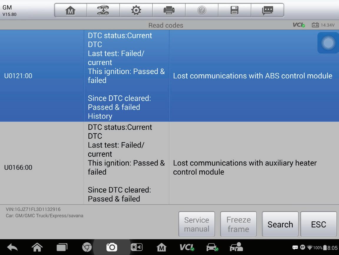

Fig. 3
battery positive (pin 16) and chassis ground (pin 4) on the DLC, with battery still disconnected:
• Connect the DVOM between pin 6 and pin 16; the
DVOM should read OL. • Connect the DVOM between pin 14 and pin 16; the
DVOM should read OL. • Connect the DVOM between pin 6 and pin 4; the
DVOM should read OL. • Connect the DVOM between pin 14 and pin 4; the
DVOM should read OL. • If the results of these tests are anything other than OL then there is either a short to voltage or a short to ground somewhere and that will have to be found and repaired.
Test #3 Voltage testing at pin 6 (CAN Hi) and pin 14 (CAN Lo) on the DLC, battery connected KOEO:
Fig. 3: This screenshot is from the G van and shows two of the many U-codes that it had stored.
Fig. 4: This is an example of a CAN bus splice pack. This is from a Sprinter Van; the NOx sensor module had shorted internally and melted the splice pack and caused the CAN bus to stop communicating.
Fig. 4

To perform our fi nal quick test at the DLC, we will reinstall the battery connection and with the KOEO (key on, engine off ) we will perform the following CAN bus voltage testing. Start by setting the DVOM to DC volts. Connect the DVOM or DSO between pin 6 (CAN Hi) and pin 4 (chassis ground) and then pin 14 (CAN Lo) and pin 4 (chassis ground). The following chart shows the expected results and what they could look like if the circuits are shorted to ground, battery or each other.
FCA vehicles and RAM trucks have started to use a Security Gateway Module (SGW) that will typically not allow any testing of the CAN bus at the DLC. To test their CAN bus systems you will have to hook up your diagnostic equipment to the Star Connector in the dash or at the SGW. Other CAN buses used for interior controls, climate and comfort systems
CAN bus Circuit Network sleeping CAN bus idle CAN bus active
CAN Lo shorted to ground
CAN Hi shorted to ground
CAN Lo shorted to battery
CAN Hi shorted to battery
CAN Hi shorted to CAN Lo
CAN Lo Pin 14 on DLC 0V 2.4-2.5V 1.3-2.3V 0V 0.3-0.5V Battery Voltage
CAN Hi Pin 6 on DLC 0V 2.4-2.5V 2.6-3.5V 0.02V 0V
Battery Voltage less 0.75V
Battery Voltage less 0.75V 2.45V
Battery Voltage 2.45V
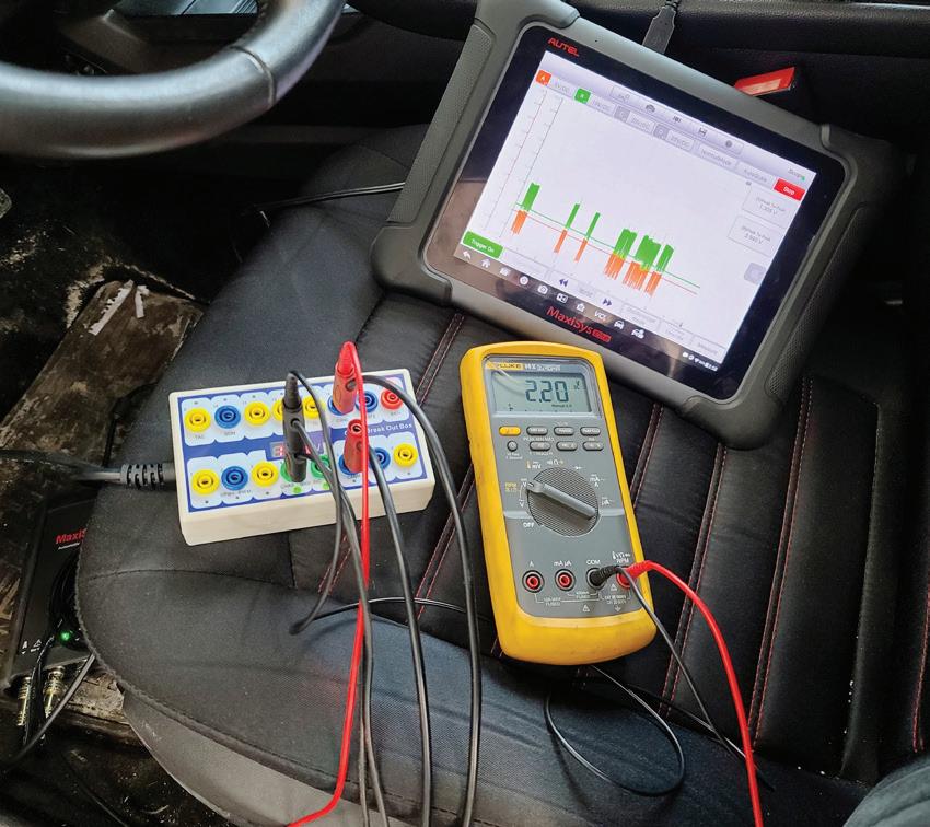

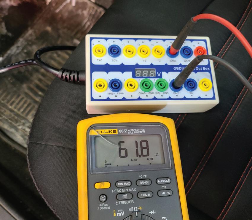
Fig. 5: Simple tools that most techs have are what I use in the early stages of looking at a CAN bus or U-code issue. It is best to hook up to a known good vehicle so you can see what a good functional systems reading looks like before you have to diagnose a faulty one.
Fig. 6: This is the OBDll breakout box that I use, they are inexpensive available online and form all the major tool suppliers and they make testing anything on the OBDll plug much simpler.
Fig. 7: With my OBDll breakout box installed this is the expected result of the testing of the terminating resistors. Remember the battery must be disconnected to perform this test. can be diagnosed in a similar fashion. Its not as convenient as the DLC, but testing is done in the same way. All CAN buses will have similar properties; a CAN hi, a CAN low and two terminating resistors across all manufacturers.
These quick tests will often point our diagnostics in a certain direction. When these test results are combined with other information gathered, such as a module that is not communicating, U-code information, and other factors like past collision damage or aftermarket installed equipment, the problem can usually be isolated easier. But a worst-case scenario diagnostic method can still happen and that requires the actual unhooking of one module at a time on the CAN bus to see if the problem is resolved.
Studying the CAN bus wiring diagram is important. Many European vehicles, older GM cars and trucks, Honda, Toyota and most FCA vehicles have CAN bus splice packs, and these can make module elimination much simpler. Late model GMs and Fords do not provide splice packs so it’s tougher on these to isolate each module.
With my DVOM/DSO hooked up to the DLC breakout box I will observe the voltages on pin 6 and pin 14 while wiggling the wires, connectors and harnesses to watch for a change that could indicate a bad, loose or corroded connection before I disconnect each module. If there is no change, I will unplug that module, observe the results and if the expected values are not restored, plug it back in and move along the CAN bus wiring diagram to the next module and repeat the process.
It’s important to note that I will also make sure that each module that I am disconnecting has proper battery voltage, good grounds and tight clean connections on the CAN bus lines, because if any of these three are missing, proper communications will not occur as well.
Often simple equipment, proper testing, a thorough visual inspection, understanding how the system works and a methodical approach will show the cause of the CAN bus issue before it gets too complicated. Having a good game plan is vital in diagnosing any issue, but when it comes to a CAN bus problem it’s essential.
Jeff Taylor boasts a 34-year career in the automotive industry with Eccles Auto Service in Dundas, Ontario, as a fully licensed professional lead technician. While continuing to be “on the bench” every day, Jeff is also heavily involved in government focus groups and serves as an accomplished technical writer.