29 minute read
THE COMPLETE BRAKE JOB

from Auto Service Professional - April 2021
by EndeavorBusinessMedia-VehicleRepairGroup

Success lies in the details
BY MIKE MAVRIGIAN
RAKE SYSTEM SERVICE IS PERHAPS
BTHE MOST CRUCIAL ASPECT of vehicle service. If the engine won’t start, the customer is stranded. If the engine or transmission causes a surge or poor acceleration, the customer is annoyed. But if the vehicle won’t stop, that’s a big problem.
ROTORS AND WHEEL INSTALLATION
When wheels are installed, the fasteners must be tightened in an even pattern to distribute clamping load, and must be tightened to the correct torque value in a consistent manner. Unequal tightening of the fasteners can easily result in undue and uneven stress to the rotor hat, potentially causing distortion/warp at the rotor disc surfaces. Naturally, a distorted rotor will lead to a bouncing/shuddering brake pedal, as well as uneven wear of the friction surfaces. Never use an impact wrench to tighten wheel fasteners, even though you view this as a time-saving approach. Set the impact wrench aside, grab your (calibrated) torque wrench and tighten the fasteners properly to specification. Yes, this requires a few additional minutes, but it can avoid a comeback and a customer complaint.
PRE-INSTALLATION WASH
Regardless of using a new or used rotor, always clean the rotor. That does not mean simply spraying the surfaces with a fast-evaporating brake cleaning solvent. While spray brake cleaning solvent is viable and certainly helps to remove surface contaminants, it’s best to hand-wash and scrub the discs with a mix of hot water and Dawn dishwashing liquid and a clean nylon brush. Why do I specially suggest using Dawn? While I’m not a chemist and I don’t pretend to know what the formula is, Dawn is simply the best soap I’ve ever
NEW STOCK ORDER FEATURE
AVAILABLE AT FIRSTCALLONLINE.COM
KEY FEATURES:
• Stock order management • Indicates any inventory stocked at customer’s location in catalog lookup • Simplifies replenishing stocking inventory
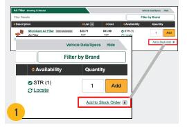
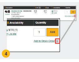
Find an item in the Catalog and ‘Add to Stock Order’
Once an item has been added to a Stock Order, an indicator will be shown on the Parts Catalog. This indicator shows the total number of Stock Orders that contain the item.
1
2
WWW.FIRSTCALLONLINE.COM

Fig. 1
used for these applications, and it works well for removing oils and particles from the machined surfaces. You can certainly follow up with brake cleaning solvent but don’t rely on the solvent alone. Seriously, wash with Dawn and hot water, followed by a hot water rinse, followed by a cold water rinse (this aids in slowing down surface fl ash rust), then dry thoroughly. Once clean, wear clean disposable gloves while handling to prevent surface contamination. Rotor disc cleanliness is a critical aspect of proper brake service.
ROTOR RUNOUT AND THICKNESS VARIATION
Whenever servicing brake rotors, always take the time to make a few measurements, even if the customer hasn’t complained about a bouncing brake pedal. Measure lateral runout, disc thickness and measure for thickness variation.
Poorly machined or abused rotors, or rotors that have been warped as a result of uneven or over-tightening of the wheel fasteners can easily create a pulsating brake pedal. Aside from the
Fig. 1: Proper brake service relies on understanding how the system operates and the use of precision measuring to inspect for disc thickness, disc parallelism and lateral runout.

Fig. 2
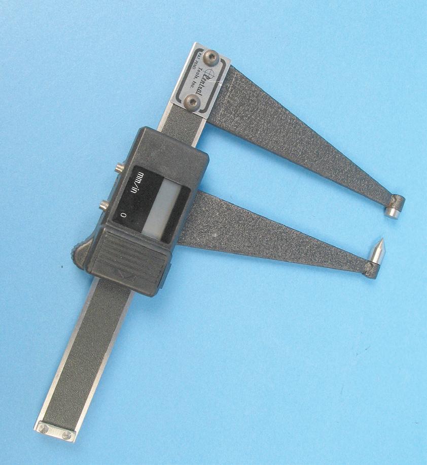
Fig. 3
annoying feel of this, if the pedal is pulsating/bouncing, this means that the pads are not in a consistent full contact with the disc surface, which results in a varying contact patch between the disc and pad, which reduces braking efficiency. Measuring lateral runout is a simple process, and there’s no reason to avoid the task.
With the wheel removed, install ALL of the wheel fasteners to solidly secure the rotor to the hub. Installing only two or three fasteners can result in an erroneous runout reading, which can easily fool you into thinking that the rotor has more runout than it actually has. This is especially critical when dealing with thin-hat rotors. Uneven and incomplete deflection at the hub can easily result in warped discs that display excessive runout.
Always install and fully torque to specification all of the wheel’s fasteners. In order to avoid damaging the nut seat surfaces, it’s also a good idea to install conical washers between the nuts and rotor hat surfaces. As an example, by installing only two nuts on a five-bolt hub, you might obtain a runout reading of, say, 0.005 inches. By installing three nuts the reading might be 0.003 inches. But by installing all five, the reading may be 0.002 inches, which would be within spec.
Mount a dial indicator to a stationary area that doesn’t move in relation to wheel rotation (frame, strut, etc.). Dial indicator mounts are available with magnetic bases or clamp-on designs. Position the dial indicator’s plunger at 90 degrees to the disc surface, and push the plunger in to provide about 0.050 inches preload. Then zero the gauge face. The plunger should feature a small roller bearing at the tip to provide a consistent reading. The plunger tip should be placed about ½-inches inboard from the outer edge of pad contact. Slowly rotate the rotor and locate the low spot, then zero the gauge again. Using a Sharpie, make a reference mark on the disc at the lowest reading location. Slowly rotate the rotor, observing the gauge, noting the highest reading. The difference represents the amount of runout. Vehicle manufacturer specifications may vary, but as a rule of thumb, the maximum allowable runout is about 0.001 inches to 0.002 inches for most applications. Depending on the rotor design, you may be able to correct for runout using an on-car lathe, or you may need to simply replace the rotor. However, before replacing a rotor that you suspect of having excess runout, make a matchmark on the rotor hat and a corresponding wheel stud, then remove the rotor and reinstall at the next clockwise position and re-check runout. You may have a situation where stacked tolerances between the rotor and the hub are creating the excess runout. Continue to relocate the rotor on the hub, checking runout with each change. You may
Fig. 2: Check rotor disc thickness with a micrometer. This allows you to determine if the rotor has worn beyond the recommended minimum thickness limit. If brake vibration is a concern, in addition to checking rotor lateral runout, a check of rotor thickness for variations can help to determine rotor condition.
Fig. 3: While a “traditional” micrometer will feature two opposing flat anvils, an ideal type of rotor tool is a digital caliper that features a flat and an opposing pointed anvil.
be able to install the rotor with the high point of the rotor aligned with the low point of hub runout.
Measure disc thickness, but avoid making any decision based on only one measurement location. Measure for disc thickness in eight locations. Refer to the minimum service limit (this should be visible on the rear cavity of the rotor hat). Even if one measurement location is within the allowable thickness, measuring for thickness variation at several spots may locate a thickness that is too close to minimum. This is sort of a double-check of findings that result from checking runout. Generally speaking, allowable thickness variation should be no more than 0.0002 inches (some OEs may spec a tolerance range of 0.001 inches to as little as 0.0004 inches).
It’s best to monitor both runout and thickness variation at the same time.
Checking lateral runout and thickness variation applies to all vehicle applications, and should not be limited only to vehicles that exhibit a brake pulsation issue. If the caliper is mounted incorrectly (damaged mounting bracket, etc.), this can place the pads at an angle that is not parallel to the rotor disc. As the pads wear, they will wear unevenly, possibly resulting in a taper wear. This places unequal pressure at the rotor, which can lead to uneven rotor wear (thickness variation).
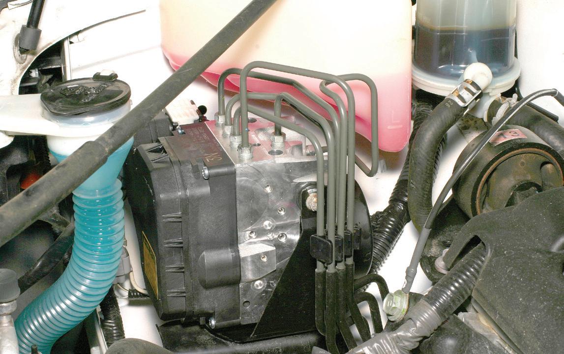
Be aware that when correcting rotors using an oncar brake lathe of the need to prevent metal shaving/ particles from contaminating ABS wheel speed sensors and tone wheels. Metal debris can be magnetically attracted to these surfaces, which can lead to false codes and intermittent ABS modulation. After rotor resurfacing, clean the sensors and tone rings, rotors, axle, etc. of any debris. Soap and hot water work well. Don’t apply compressed air to blow particles away, as this can cause the particles to expand contamination.
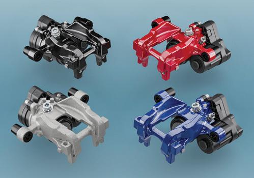
CALIPERS
A brake caliper is “simply” a rigid housing that contains one or more pistons that move inward under hydraulic pressure to make the pad friction material contact the rotor disc surface. Sounds simple enough. However, even the best quality new caliper can’t operate efficiently if mounting procedures aren’t followed. Depending on the style (floating or fixed), the caliper must be mounted so that the pads are parallel to the brake rotor disc. If a caliper is mounted without attention to the attachment points (rust/corrosion on mounting surfaces, etc.), this can create a non-parallel result, allowing the pads to contact the rotors at an angle, minimizing full pad contact. This results in less than efficient braking performance and taper-wears the pad friction material. Floating calipers that are attached to a caliper bracket rely on a pair of pins that allow the caliper to slide in/out. As the brake pedal is
Fig. 4: The machined grooves seen on this Dodge Charger police car aid in self-cleaning the pads. The increased surface area created by the grooves also helps to dissipate rotor heat. If the vehicle was originally equipped with grooved or slotted rotors, it’s best to replace them with identical style rotors.
Fig. 5: The use of an on-car brake lathe can cure an annoying pedal pulsation issue. Rather than truing a rotor that has a bit of lateral runout or thickness variation, machining a rotor on-the-vehicle eliminates variables such as potential hub runout. Once machined, the rotor must always be installed in the same clock position.
Fig. 4
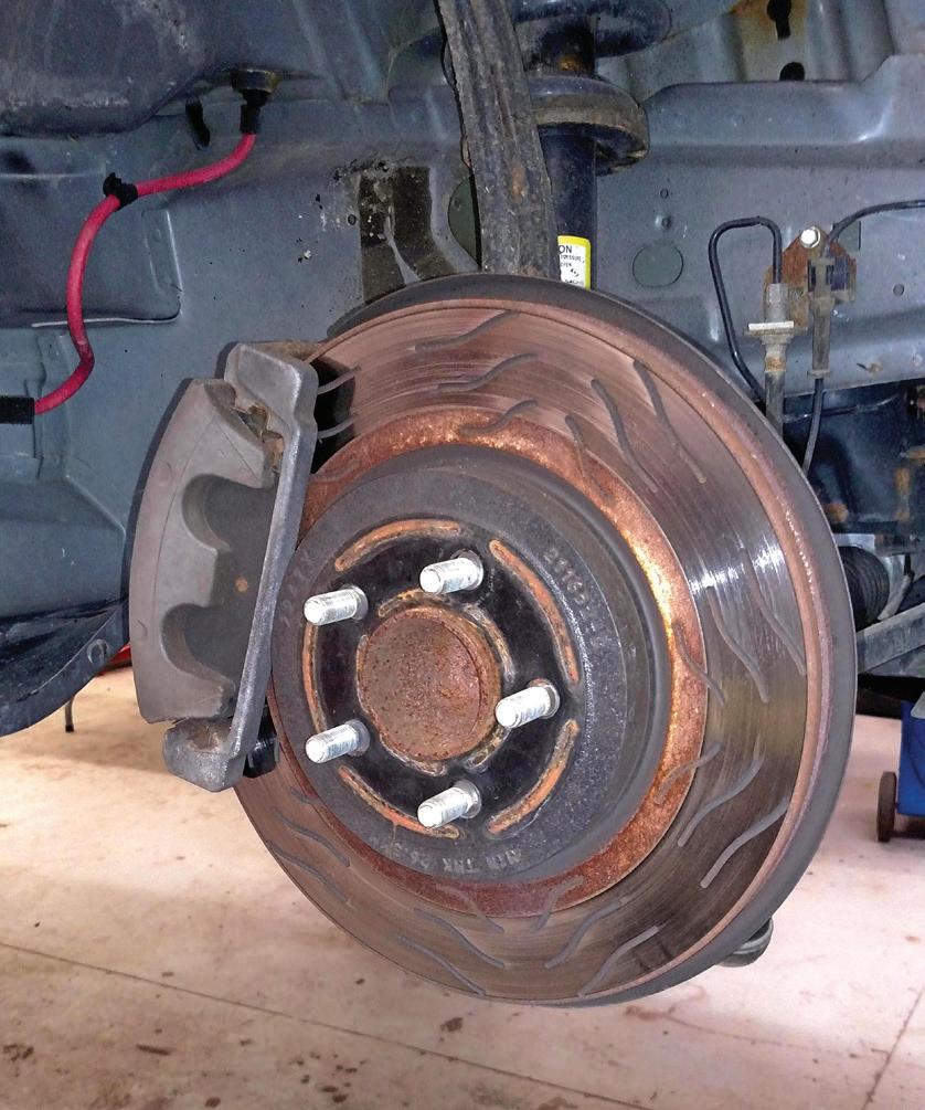
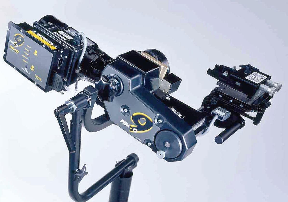
Fig. 5
How to find the right parts fast and increase your shop’s productivity and profitability
FIND. ORDER. DELIVERED.
YOUR TIME MATTERS
www.myplace4parts.com
THERE’S A REASON TECHNICIANS EVERYWHERE
recognize MyPlace4Parts as the easiest, fastest, and most accurate way to find parts. The system is loaded with features that provide everything you need so you can spend less time clicking and more time fixing.
While other systems restrict what you can see and buy primarily to application specific parts, MyPlace lets you see and buy everything: Application parts, accessories, tools, shop supplies, chemicals, and more. It also uses Googlepowered search capabilities. The system allows for intuitive shortcuts and key word searches that speed up the lookup and ordering processes.
MyPlace4Parts puts power into the palm of your hand with its mobile VIN scanner, which instantly loads scanned VINs from your Android or Apple phone or tablet. There’s only one button needed to upload VIN data to MyPlace, enabling quick, accurate parts lookup to help increase bay productivity and lookup accuracy.
MyPlace also features plate-to-VIN lookup. All you have to do is enter the license plate number and state of issuance, and MyPlace instantly populates the VIN number! The App is free to download from the Google Play Store and the App Store.
Using MyPlace is like driving a fine car that’s loaded with features for a smooth and enjoyable ride, including: • Comprehensive Interchange. Whether it’s simple aftermarket-to-aftermarket interchange or a complicated OE to aftermarket interchange, we’ve got you covered. • Custom Parts Lists. MyPlace4Parts allows you to create custom lists for items in stock or frequently ordered parts, including everything from replacement items for fleet vehicles you maintain to regular stock orders, shop supplies, and materials. • Delivery Times. The system also gives you an estimate on when to expect your parts delivery based on order time. This allows you to more accurately schedule your customer’s drop-off and pick-up times. • Make-Specific Lookups. MyPlace knows what brand was OE on the vehicle you were repairing, even recognizing different brands for left side and right side oxygen sensors. The brand you see listed first is the one specified by the OE.
Between shortcuts that “learn and remember” how you like to search, key word recognition, custom parts lists you can save, links to supplier and technical sites, and mobile VIN scanning capabilities, MyPlace4Parts has you covered on all parts-ordering fronts. No other shop e-commerce tool does more.
applied, hydraulic force pushes the piston and inboard pad toward the rotor disc, causing the caliper to slide inward, allowing the outboard pad to contact the rotor. If the pins are rusted, pitted, and have less than a smooth surface, the caliper will either cock (due to unequal sliding action between the two pins) or drag and result in insufficient pad pressure at the rotor and/or not retract when the pedal is released, resulting in the pad(s) dragging against the rotor, causing premature pad wear, elevated brake temperature and likely glazing of the rotor surface. Failure to clean rust buildup and properly lubricate caliper brackets is a major cause of brake noise, premature wear and increased stopping distance.
When changing pads, the caliper piston(s) will have moved further outward as the old pads become thinner. In order to install the caliper now equipped with new and thicker pads, the piston(s) must be compressed in order to provide the proper clearance for pad-to-rotor disc installation. Avoid using large channel lock pliers to push a piston. This can cause the piston to slightly cock in its bore, and you stand a chance of damaging the piston contact face and potentially tearing the piston seal. Rather, use a dedicated piston compressor tool that provides a full-width flat face against the piston(s).
If the old pads have experienced severe wear and have become very thin, the piston(s) have been operating beyond their intended bore path. If the pads have been worn thin, an increased area of the piston(s) has been exposed to the elements for a while, possibly allowing grit to build up on the piston walls. Pushing the dirty piston fully back into its bore can result in forcing grit into the seal and bore. This can result in a sticky piston that isn’t able to freely travel within its bore. If the piston(s) don’t travel easily and smoothly, it’s time to replace the caliper.
Even if piston condition seems OK, always inspect the bleed valve to make sure it can be opened. If a bleed valve is severely stuck, you can be faced with a stubborn bleed, or even if it moves, it may not successfully seal when closed. If you suspect a bad valve and were able to remove it, installing a new valve may or may not provide a fix, depending on the condition of the caliper’s female threads and valve seat. Rather than wasting time and effort to repair, just replace the caliper.
Also, check the hex size of all bleeder valves before you begin installation. It’s common, especially for some remanufactured calipers, to have bleed valves that feature a different hex size. It can make you crazy when faced with constantly hunting for a different line wrench size if each caliper has a different hex size. Knowing that you have the correct line wrench(s) handy from the start will save time and aggravation. In some cases, during the remanufacturing process, correcting damaged bleed valve female threads may have resulted in re-machining to a larger size, which may change the size of the hex (for example, original calipers may have featured bleed valves that require

Fig. 6
Fig. 6: Prior to replacing pads, the caliper pistons must be retracted in order to provide room for the new and thicker pads. Never use channel pliers directly against the piston surfaces. Place a spare pad or flat heavy gauge steel plate against the pistons and use a C-clamp to compress, or use a dedicated piston compressor tool that engages the pistons with a flat plate. Using pliers directly against the pistons can easily cause piston damage.

Fig. 7: Before installing the wheel, apply a thin coating of a high heat anti-seize paste to the hub, especially around the hub flange. This will prevent rust buildup and corrosion caused by dissimilar metals when an aluminum wheel mated to an iron hub, easing future wheel removal.


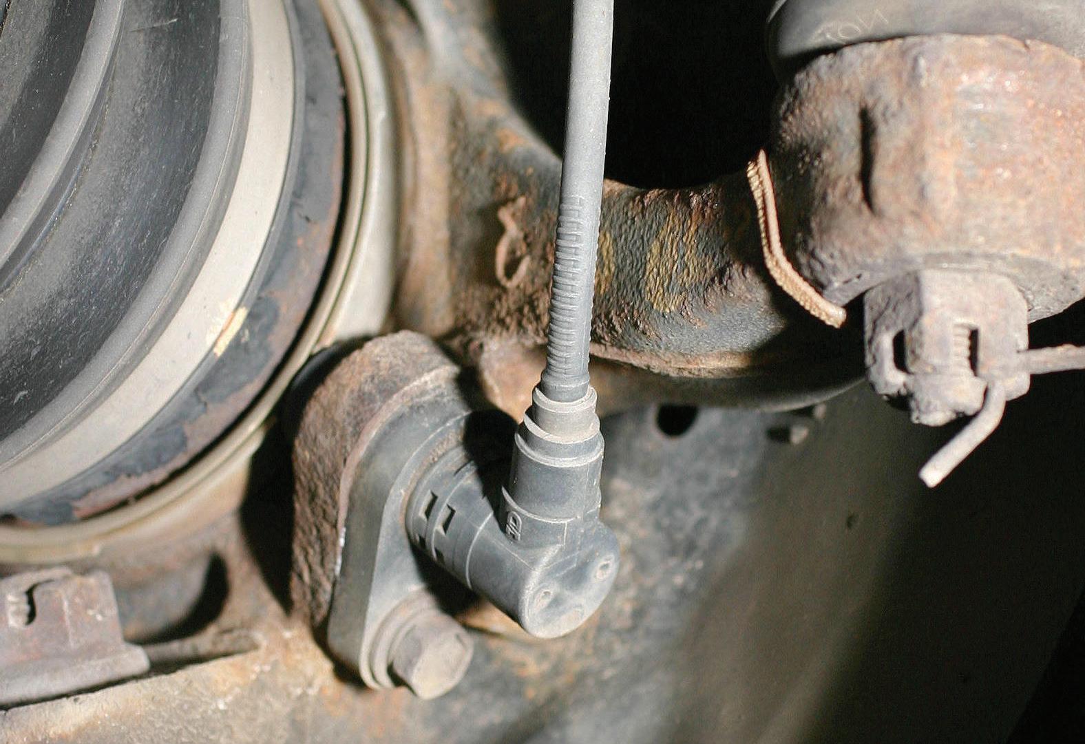
Fig. 8
Fig. 9

Fig. 10

a 10mm line wrench, but the reman caliper may feature a bleed valve hex size of 5/16 inches, etc.). Check this from the start to avoid the need to travel back and forth to your tool chest.
Sliding calipers that ride on smooth-wall guide pins must be inspected for cleanliness and smooth engagement of the pins to their bores. If guide pin boots are damaged, this is a clear indication that the pins are probably scored or rusty. Simply replace it with new pins and new boots, applying a thin coat of high-temperature caliper pin grease prior to installation. Never install guide pins dry.
Fig. 8: Prior to removing a wheel speed sensor, clean the area adjacent to the sensor to prevent debris from entering the exposed sensor mounting hole.
Fig. 9: Tapered pad wear indicates caliper misalignment and is not to be blamed on the pads. Closely inspect the caliper mounting to check for a bent bracket, or debris or faulty hardware.. (Photo courtesy of NAPA)
Fig. 10: Uneven pad wear, where the pads on the same axle show different rates of wear, indicate a sticking caliper.
PADS
Inspect the original pads for taper or uneven wear. Tapered wear indicates that the caliper is not aligned properly with the rotor disc. This could be due to sticking slider pins on a floating caliper design or a damaged/bent caliper mounting bracket. Note that another area to inspect are the caliper mounting bracket mating surfaces, as rust/debris may have been trapped between the mounting bracket and steering knuckle during a previous brake job, which may have cocked the bracket.
If the pads on a floating caliper feature unequal wear, this is an indication that the caliper is not able to slide properly. This can prevent the outboard pad from making adequate contact with the rotor, relying on the inboard pad to do most of the work. The result: the inboard pad becomes more worn than the outboard pad. This is an example of why it’s so important to make sure that the caliper slide pins and bushings are clean and well lubricated.
If unequal and/or excessive pad wear is found on a fixed caliper application, the guide ears of the pad backing plates may be sticking to the stainless steel guide/sliding clips, or the backing plate ears may be stuck against the caliper, causing the pad to be stuck against the rotor without being able to release the pad. Again, this emphasizes the need to clean/replace the pad hardware so that the pads are able to move freely within their operating range. Lube the friction surfaces (where the pad backing plate contacts the caliper and/or guides) with a silicone-based lubricant that offers a high melting point (a dedicated brake lubricant is recommended, designed specifically for pad/caliper lubrication).
When installing new pads, be sure to remove all rust/debris from the caliper in those areas where the pad backing plate makes contact. Test-fit the pads to the caliper to verify freedom of movement. For instance, if the pad backing plate ears make significant contact with the caliper resulting in a too-tight fit, in some cases when using “bargain” pads, the backing plate ears may need to be carefully filed down to obtain adequate clearance. The best approach is to use only
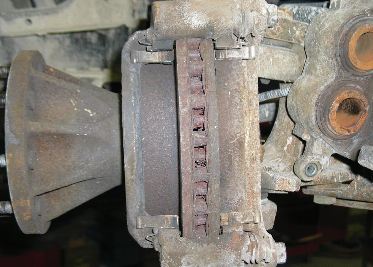
Fig. 11 Fig. 12

high quality replacement pads from established manufacturers such as Brake Parts Inc., Wagner, Advics, etc., to obtain pads with tight quality control.
Naturally, you never want to introduce any lubricant to the rotor disc of pad friction material. When installing new pads, make sure that your hands are clean and free of contaminants.
MASTER CYLINDERS
When you encounter a low, sinking or spongy brake pedal, one suspect is the master cylinder. The cylinder may be bypassing, allowing fluid to leak past the piston seals internally, preventing a pressure buildup. This applies to all vehicles.
Master cylinders feature lip cup seals. This design allows for the seal to improve as the pressure increases. Another feature of this seal is that it does not create a vacuum when the piston retracts.
As the pedal is depressed, the piston is pushed in the forward direction. The lip cup seal, attached to the primary piston, generates pressure in the primary chamber first, which in turn, forces the secondary piston forward, building pressure in the secondary chamber. As the pressure increases in both chambers, the edges of the seal are pressed against the bore of the master cylinder. As pressure increases, sealing is improved.
In the manufacturing process, the testing procedure for master cylinders is done at low pressure. Lip cup seals are more likely to fail under low pressure.
Perform an isolation test. Use the proper tool that won’t damage the flexible hydraulic brake hose, clamp off all brake hoses. Press down on the brake pedal, and if the pedal is low or spongy, remove the brake lines from the master cylinder, and install threaded plugs in the outlets (not plastic plugs).
Press down on the brake pedal and release the pedal and wait approximately 10 seconds. This allows the quick takeup valve to open and the air to escape through the master cylinder compensating port, and the fluid in the reservoir to enter the bore of the master cylinder. Once air stops coming up into the reservoir, or the pedal becomes firm, apply light pressure to the pedal, and observe if the pedal continues toward the floor.
When the master cylinder ports are plugged, and the air is bled out of the bore, the pedal should be high and hard under low pedal effort or high pedal effort. If the pedal sinks under either condition, the seal is damaged and the master cylinder should be replaced.
A sinking or soft/spongy brake pedal is generally indicative of a master cylinder problem. The piston inside the master cylinder is likely allowing brake fluid to pass the piston seals, preventing the build-
Fig. 11: Prior to installing any wheel speed sensor, make sure that the installation surface is clean and dry. Naturally, the sensor must be clean, as well. Be sure to lightly lubricate the sensor O-ring with a nonevasive lubricant in a pinch, Vaseline works well). Never attempt to install the sensor with a dry O-ring, as the risk of tearing the O-ring is high.
Fig. 12: Inspect rotor vanes. Heavy rust or debris buildup in the vanes can severely limit the rotor’s ability to disperse heat.

Fig. 13: An accurate method of checking for hydraulic pressure at the calipers is to use a pressure transducer (pressure pad gauge).
Fig. 14: Install a pressure pad in place of one brake pad at each of the same axle’s brake locations. Orient the pressure pad between the caliper piston and the rotor. up of braking pressure. The seals feature a lip cup style that generates sealing as pressure is increased. This type of seal does not create a vacuum when the piston retracts as the pedal is released. As the brake pedal is depressed, the piston pushes forward. The seals allow pressure to build in the primary chamber first (for front brakes). Pressure is then built up in the secondary chamber. Damaged or worn seals allow fluid pressure to leak past the seal and back into the fluid reservoir. When the brake pedal is depressed, bad seals simply allow the fluid to pump between the bore and reservoir instead of being pressure-forced through the lines to the brakes. If this is the case, and bad seals are the issue, no external leaks will result. Be aware that a cast iron master cylinder that features a poor quality casting may have casting pores that have opened up and result in external leakage. Always check for external leaks first. If the master cylinder housing shows signs of external leaks, we know that we have a bad part, so replace the master cylinder (with proper bench bleeding and system bleeding) before wasting time with further diagnosis. Even if we still have a poor pedal, at least we have replaced a known bad part.
When diagnosing the hydraulic braking system, first perform an isolation test. Using the proper clamping tool, clamp off all four brake hoses. Depress the brake pedal. If the pedal is low or spongy, remove the brake lines from the master cylinder and install plugs at the line outlet ports.
Depress the brake pedal again, and then release the pedal. Wait for about 10 seconds. This allows the quick take-up valve in the master cylinder to open, allowing air to escape through the cylinder compensating port, allowing fluid in the reservoir to enter the master cylinder bore. Once air stops coming up into the reservoir, or if the pedal becomes firm, apply light pressure to the pedal and observe if the pedal continues to drop to the floor.
When the master cylinder ports are plugged and air is bled out of the bore, the pedal should be high and hard under low or high pedal effort. If the pedal drops, the seal(s) is damaged and the master cylinder must be replaced.
Here’s a tip if you encounter a problem after installing a new master cylinder: As noted by Wagner Brakes, If a new master cylinder has been installed


Fig. 15
Fig. 15: Apply brake pedal pressure. The gauge will show the amount of pressure being produced. In this example, the gauge showed 980 pounds under initial pressure. As full force was applied, the gauge showed 3,500 pounds.
Fig. 16: When pedal pressure was released in this example, the right front pressure quickly dropped to zero while the left front showed a very slow pressure drop.
Fig. 17: The red needle on the right gauge remained at peak pressure as a reference, and the black needle dropped to zero when pedal pressure was released. Since the left gauge showed a very slow pressure drop, this indicated that the left front caliper was dragging/sticking.
Fig. 16
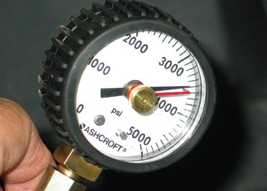
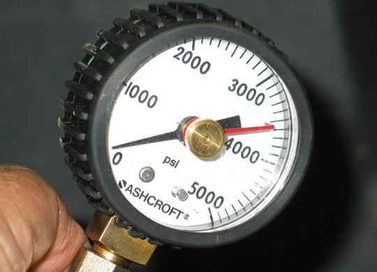
Fig. 17

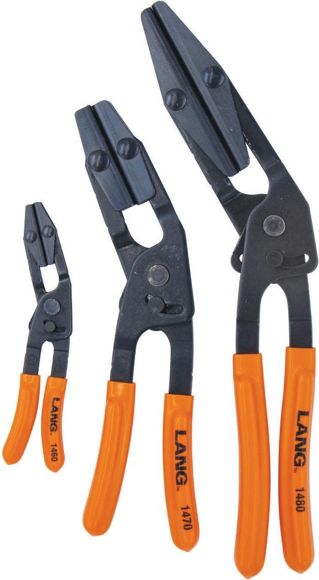
HOSE


PINCH PLIERS


• SELF-LOCKING FEATURE HOLDS
AFTER PRESSURE IS APPLIED • SIMPLY PULL HANDLES APART TO RELEASE • MADE FROM HIGH CARBON, HEAT TREATED,
STEEL COMPONENTS AND PLATED WITH
BLACK OXIDE COATING • IDEAL FOR RADIATOR, VACUUM, AND FUEL LINES
HOSES, PLUS OTHER FLEXIBLE MATERIALS

MADE FROM HIGH CARBON, HEAT TREATED,

#1500
3-PIECE SET
Also available individually.
MADE IN U.S.A.
WWW.LANGTOOLS.COM

Lengths: 6", 9-3/4", and 13"

Fig. 18 Fig. 19

and the system is manually bled, the brake pedal is often depressed completely, moving the primary and secondary pistons to their extreme forward position. The primary piston may stick even though there are springs attempting to push it back into position. When a master cylinder is assembled, the seals and cylinder bore are lubricated for a positive seal. This, combined with any air trapped in the system can cause a vacuum lock in the cylinder. You can verify this condition by removing the master cylinder from the booster without disconnecting the brake lines. You may notice that the piston has not returned fully rearward and is not resting on the snap ring. Sometimes connecting a pressure bleeder and opening the wheel bleeder screws will cause the piston to return. You can also tap lightly on the housing, with bleeders open, to free the piston. Once the piston has returned to its correct position and air is bled from the system, the problem should not recur.
As anyone who is experienced with servicing brake systems will attest, we need to be careful when choosing block-off plugs for master cylinder ports, since a variety of thread sizes and pitches are in use, as well as line-to-port sealing designs. Installing an incorrect plug can easily result in damaging the port threads, which automatically requires scrapping the master and obtaining another new unit.
Improper bleeding procedures can also cause damage to a previously-good master cylinder. If a master cylinder has been operating correctly for many miles of use, and the system is then bled in the course of a normal brake job, the master cylinder’s piston seals can be damaged if the pedal is pushed fully to the floor during bleeding. Over the course of long term use, the piston inside the master cylinder travels a relatively short distance. If the system was poorly maintained and the brake fluid has absorbed excess moisture, the end of the piston bore may feature corrosion build-up in the end of the bore that normally never experiences piston travel. If, during the bleeding process, the pedal is pushed all the way to the floor, the piston is now pushed into the corroded area, possibly damaging the seal. To avoid this during a bleeding job, you can place an obstacle, such as a block of wood, under the pedal to avoid overtraveling the piston.
Whenever servicing a vehicle’s brake system, examine the fluid in the reservoir. If it appears dirty, vacuum the fluid out of the reservoirs and replace with fresh fluid prior to bleeding. This reduces the risk of retaining contaminants in the hydraulic system.
Always remember to bench-bleed any master cylinder that has been emptied of fluid. An improperly bled master cylinder will result in a low, soft pedal. This applies to a new unit as well as a used master cylinder that has been drained. This involves connecting temporary transfer tubes from the output ports into the reservoir(s), filling the reservoir(s)
Fig. 18: Before replacing a master cylinder, inspect the depth of the piston’s pushrod cup, as a difference in cup depth as compared to the original master cylinder may require a length adjustment to the pushrod that exits the power booster. Start by measuring the distance from the master cylinder mating flange to the rear edge of the master cylinder.
Fig. 19: Then measure the distance from the rear edge to the piston cup seat. Perform these measurements on both old and new master cylinders to see if they differ.
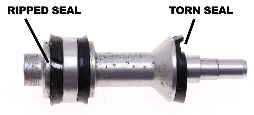
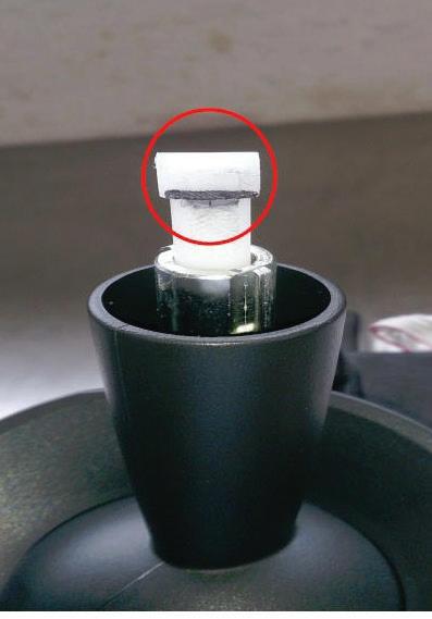
Fig. 20: Damaged master cylinder piston seals can result in internal leaks/bypass, preventing proper fluid routing and causing a soft or dropped pedal. (Image courtesy Brake Parts Inc)
and slowly pushing the piston fully forward and slowly releasing several times until all traces of air bubbles are eliminated. In some cases, even after bench bleeding via the output ports, it may be necessary to also bleed via the master cylinder’s bleed ports (if so equipped). Once all trapped air has been released, be sure to keep the fluid level in the reservoirs sufficiently high to avoid exposing the outlet orifices at the bottom of the reservoir wells before installing the master cylinder. Naturally, during system bleeding, constantly keep an eye on the reservoir fluid level to avoid running the master dry.
A mention regarding master cylinder reservoir fluid level is worthy of note. A reservoir will feature min/max fluid level marks. Never overfill fluid above the max indicator. When brakes are applied and the friction material contacts the rotors and/or drums, heat is generated in the system, which causes the brake fluid to expand. The expanded fluid rises the level in the reservoir. If overfilled, the fluid can topout and have nowhere to go, resulting in potential brake drag, which results in overheated brakes and premature friction material wear. Always pay attention to the reservoir fluid level. If under-filled (below the min line), you run the risk of exposing the master cylinder ports dry, which reduces or eliminates hydraulic pressure as well as sucking air into the system.
ABS GLITCH AFTER HUB REPLACEMENT?
ABS light may be on and/or false ABS activation may occur following wheel bearing hub replacement on only one side of an axle.
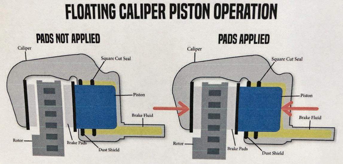
Fig. 21

Fig. 22
Fig. 21: Example of a floating caliper. When the brakes are applied, the piston moves out toward the rotor disc and the inboard pad is pushed against the rotor. As this happens, the caliper slides inward, pushing the outboard pad against the rotor. If the caliper is not allowed to slide, the inboard pad will experience undue wear. (Image courtesy of Brake Parts Inc.)
Fig. 22: Here’s an example of a fixed caliper design featuring inboard and outboard pistons. The caliper is mounted rigidly and does not move. Hydraulic pressure applied to inboard and outboard pistons allow both the inboard and outboard pads to move against the rotor simultaneously. Any unequal force at either pad can result from sticking pistons and/or limited/stuck pad travel where the backing plates drag/seize on guide surfaces. (Image courtesy of Brake Parts Inc.)