27 minute read

Achieving critical fastener torque

Next Article
Business

Business

Applying torque to a threaded fastener is merely the act that ful lls the goal of achieving proper clamping force

Compiled by Mike Mavrigian

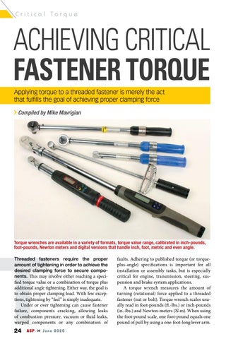
Torque wrenches are available in a variety of formats, torque value range, calibrated in inch-pounds, foot-pounds, Newton meters and digital versions that handle inch, foot, metric and even angle.

TThreaded fasteners require the proper faults. Adhering to published torque (or torqueamount of tightening in order to achieve the plus-angle) speci cations is important for all desired clamping force to secure compo- installation or assembly tasks, but is especially nents. is may involve either reaching a speci- critical for engine, transmission, steering, sus ed torque value or a combination of torque plus pension and brake system applications. additional angle tightening. Either way, the goal is A torque wrench measures the amount of to obtain proper clamping load. With few excep- turning (rotational) force applied to a threaded tions, tightening by “feel” is simply inadequate. fastener (nut or bolt). Torque wrench scales usu-

Under or over tightening can cause fastener ally read in foot-pounds ( .-lbs.) or inch-pounds failure, components cracking, allowing leaks (in.-lbs.) and Newton-meters (N.m). When using of combustion pressure, vacuum or uid leaks, the foot-pound scale, one foot-pound equals one warped components or any combination of pound of pull by using a one-foot-long lever arm. 24 ASP June 2020

Before installing and tightening any threaded fastener, the threads, both male and female, must be clean and free of irregularities in order to achieve desired tightening value. Whenever possible, and especially for cylinder head bolt applications, use a dedicated thread chaser (not a cutting tap!) to clean female threads.

There are four basic types of torque wrenches commonly used for automotive applications: the flex bar, the dial indicator and the sound indicating (micrometer) types, and digital torque wrenches that provide a visual (indicating light) and audible (buzz or beep) alert when the programmed torque is achieved.

The flex bar type (also called the scale type or beam type) features a stationary needle that runs the length of the shaft handle. The needle indicates applied torque against a printed scale that’s located at the base of the handle. This type of torque wrench offers no pre-set limit, and there is no felt or audible “release” when a specific torque value is reached.

The dial indicator type features a dial indicator readout for visual display. Both the flex bar and dial indicator types provide visual displays of applied torque. The sound indicating type will signal applied torque by momentarily releasing the wrench a few degrees when the preset torque value is reached. The release is usually accompanied by a “click” sound. However, there are some release-type torque wrenches that will release upon reaching the preset torque but may not provide an audible click. The release/click type wrench is adjusted by means of a micrometer scale on the handle.

If the torque wrench releases momentarily and/or clicks, this is referred to as a “signal” type. The “indicator” type refers to the visual display units such as the flex bar or dial indicator style.

Any adjustable torque wrench (the commonly used micrometer-handled click type, for

Some micrometer type “click” torque wrenches are designed only for unidirectional applications. If the tool is labeled for “Right Only,” it should not be used for counter-clockwise/left turning, which can damage the internal mechanism. If left-hand threads are encountered, you must use a torque wrench designed for left turns.

example) should be set at its lowest torque reading when not in use. This is something that many technicians commonly forget. If left stored at a high-torque setting, the calibration may be affected over a long term. When you’re done with the wrench, readjust it to the minimum setting before storing it in the toolbox.

Never abuse a torque wrench. It’s designed as a precision instrument and should NEVER be used as a pry bar or as a disassembly/assembly tool. A torque wrench should be used to achieve final clamping load only. Handle all of your “wrenching” duties with common wrenches, and only use the torque wrench as the final adjuster to reach a specific torque level. Don’t use it as your all-around wrench.

When using an adjustable torque wrench, be careful not to overtighten by applying torque past the release point. At very low settings, the “click” may not be heard, especially in a noisy shop. It’s best to become familiar with the “feel” of the release, rather than relying only on the sound of a click.

When using an indicating type torque wrench (such as a flex bar or dial indicator type), try to read the indicator while viewing it at 90-degrees to its surface. Reading the indicator at an angle will provide errors due to line of sight.

Most torque wrenches operate accurately only when held by the center of their handle grips. Don’t use cheater bars to extend your grip further away from the wrench head, and don’t grab the handle closer to the wrench head. Only grip the wrench by its designated grip area.

Among the applications where installed torque (and possibly torque-plus-angle) tightening, engine block main caps and cylinder heads are examples where tightening and clamp loads are critical.

TORQUE VALUES AND FASTENER CLAMPING Once the underside of the bolt head makes contact with the parent surface, since the head can’t enter the threaded hole, any additional rotation of the bolt head begins to slightly stretch the bolt. When tightened properly (to specification), the bolt has stretched within its designed elastic range.

When the bolt is loosened, the elasticity of the bolt theoretically allows it to return to its normal, uninstalled length. An analogy is to view the bolt as a rubber band. If the bolt is under-tightened, and does not enter its elastic range, it won’t provide enough clamping force. If overtightened beyond its elastic range, the bolt can enter its yield point, and can permanently weaken. If there’s no elasticity, the bolt can’t do its job in terms of providing clamping force.

Bolt or stud diameters are based on the load required for component clamping performance. That’s why 1/4-inch bolts may be used in one location, and 3/8-inch bolts in another. A smaller-diameter bolt requires less torque value to achieve ideal clamping load, and a larger-diameter bolt requires more torque value to achieve ideal clamping load. Although not a perfect analogy, you can somewhat view threaded fasteners as “fuses.” The diameter is based on the requirement for the specific job, just as the amp rating of a fuse is based on the requirement for a particular circuit.

Tightening a threaded fastener should never be a matter of guesswork. Especially for critical fasteners, such as any involved in the brake sys26

Proper tightening of connecting rod caps is another example of the need for accurate tightening. Rod cap fasteners that are undertightened can work loose, increasing bearing clearance and resulting in low oil pressure, damaged bearings, with the very real potential for crankshaft damage and catastrophic engine failure. Over-tightening can stretch the rod bolts beyond their designed yield, resulting in cap separation and engine failure. Rod fastener tightening is one of the most critical applications for achieving proper clamp load.

tem, steering system, suspension, engine, transmission, differential and wheels, all threaded fasteners must be tightened to their specific-application torque value.

While many folks hand-tighten by “feel,” the more astute rely on a monitoring device such as a torque wrench. Unfortunately, when most folks use a micrometer-type (click type) torque wrench, they simply adjust the wrench handle to the desired force (if the wrench is the micrometer type), slap a socket onto the wrench, stick it over the bolt head and tighten until they hear a click, without regard to the variables that may enter the picture. Excess friction can occur if galling or “thread seizing” takes place. This is especially common with threaded fasteners made of alloys such as aluminum, stainless steel and titanium. If galling occurs (at any level of severity), this will make your torque readings inaccurate, since the galling effect will add significant friction at the thread mating area, which will result in a severely under-tightened fastener (since your torque reading or indicator click will take place well before your desired clamping load is reached).

Several factors can affect fastener tension, including type of material, material hardness, lubrication (or lack thereof), fastener hardness, surface finish/plating, thread fit and tightening speed.

Properly tightening cylinder head fasteners is obviously important to maintain a dynamic seal for the head gasket. Many of today’s engines recommend a tightening method that involves achieving an initial torque value, followed by a specific additional fastener head rotation. This is called torque-plus-angle tightening. Digital torque wrenches are available that allow completing both steps with a single tool.

TIPS AND PRECUATIONS • Never attempt to adjust a torque wrench outside of its intended range. For example, if the range maximum is 100 ft.-lbs., do not try to ad-

Digital/electronic torque wrenches allow easy push-button setting for value. Once the desired value has been reached, depending on tool design, the wrench emits an audible beep or a combination of an alert sound accompanied by LED lights that allow you to observe both approaching value and final value.

just the wrench higher and “guess” what the final value would be. For example, a “smidge” beyond the 100 ft.-lbs. mark on a 100-max torque wrench does not mean that you’re achieving 105 or 110 ft.-lbs. • Threads, both male and female, must be

In those cases where cylinder head studs are involved instead of bolts, install studs only finger-tight to the block. Applying desired torque to the nuts will result in clamping load. Do not double-nut studs and try to torque them in place. This will cause the studs to splay slightly and can fracture the block.

clean and free of contaminants, rust and burrs. Any debris or thread condition issues will adversely affect the achieved torque value. • Never use a torque wrench as a general-service wrench to tighten or loosen fasteners, or as a pry-bar. Use only for achieving final torque values. • Pay attention to tool design. Don’t use a ratcheting type or dial type torque wrench to remove fasteners (left-hand operation can damage calibration), unless the torque wrench has been specifically designed for left-hand operation. • When tightening, slow down! Fast tightening creates more thread friction and heat, which can lead to thread galling. Tightening too quickly can also lead to inaccurate tightening, as the torque wrench must overcome the increased friction. • When you reach the torque limit (your desired torque value), approach this slowly and watch the needle or feel for the click. If you tighten too fast, you may pull the wrench past the preset limit (unknowingly adding a few more footpounds of torque). • As recommended in assembly instructions, apply the required lubricant to the threads before assembly. This may involve engine oil, molybdenum disulphide, an anti-seize compound, a specifically recommended low-friction lube or an anaerobic thread locking compound, depending on the application. TORQUE AND FRICTION When rotational torque is applied to a nut or bolt head, most of the input is spent in overcoming 28

If a digital torque/angle wrench is not available for applications that call for torque-plus-angle, an inexpensive angle gauge adapter may be used. However, this will add time to the job, as you need to switch from the torque wrench to the angle gauge for each fastener. Of course, painting a dot on the bolt head and visually observing (and guessing) at angle rotation is an option, although not as accurate.

friction. At the end of the process, 85% to 95% of the energy transferred through the wrench has been lost. In other words, the clamp load itself may only represent 5% to 15% of your effort.

Because of this frictional loss factor, slight variations in the frictional conditions can result in huge changes in the resulting preload. Variables include surface roughness, surface finish, lubricant, load range reached, dimensions, temperature and torquing sequence.

Since torsion is a function of the imposed friction, a given material reaches its yield strength sooner when the friction is high as opposed to low. During tightening, the apparent yield strength drops by 10% to 20% from the yield strength measured in tensile strength.

As mentioned earlier, thread lubrication, or lack thereof, can greatly affect the desired clamping load. Pay attention to the instructions, whether you’re following recommendations from the auto maker, part maker or fastener maker. Some torque specifications may be published based on the use of dry threads, threads lubed with engine oil or lubed with a special very slippery moly-based or synthetic lubricant. If a torque value is based on the use of engine oil, but the installer applies a super-slippery lube that reduces friction vastly greater than engine oil, the fastener will likely be over-tightened, potentially over-stretching the fastener. If the torque value is based on the use of a specific lube that greatly reduces thread friction, and the installer uses

Example of a foot-pound setting on an electronic torque wrench. When you set the tool for the desired value, the value will be displayed. Once you tighten to the point when you hear/see the alert, the display will also show what value you have achieved. For instance, if you continued to pull after you hear the beep, the display will show the actual result. If you set the wrench for, say, 75 ft.-lbs. but you pulled a bit too far, the display may read 77 ft.-lbs., etc. This provides an instant verification of the final value.

engine oil instead, the fastener may be undertightened. Read the instructions, especially when installing critical fasteners to components such as cylinder heads, main caps or intake manifolds. This is particularly important if using aftermarket fasteners that may be designed to use a specific type of lubricant and possibly a different torque value than the OE spec.

CHOOSE THE CORRECT TORQUE WRENCH It’s important to choose a torque wrench that features your torque value requirement in the middle of its range. For instance, if you need to tighten a fastener to an upper range limit of 100 ft.-lbs. Instead, use one that features a range of, say, 25 – 250 ft.-lbs. If tightening a fastener to 50 ft.-lbs., use a torque wrench that has an upper limit of about 100 ft.-lbs., etc. Generally speaking, torque wrenches perform at their most accurate level when the application is in the midrange area of the wrench’s calibration spectrum.

USE OF ADAPTERS/EXTENSIONS On occasion, you may need to use an offset wrench extension on the torque wrench due to fastener access. We’re not talking about the use of a socket extension bar. Rather, we’re referring to a wrench extension that makes the total length of the torque wrench longer, from center of the grip to the point of contact with the fastener.

Electronic digital torque wrenches can easily be set to various modes, for instance at N.m (Newton-meters).

If an adapter is used that effectively lengthens the wrench, a compensation calculation must be made in order to achieve the desired torque value. Because the use of an offset wrench creates greater leverage, this requires a change in your wrench torque value setting at a slightly lower setting to avoid over-tightening. Following is a method of calculating this change:

E — Effective length of extension, measured along the centerline of the torque wrench. L — Lever length of the wrench (from center of the wrench drive to the center of the adapter’s grip area). TW — Torque setting on the torque wrench. TE — Desired torque.

FORMULA:

L divided by L+E, x TE = TW

Let’s say that you want to torque a bolt to 70 ft.-lbs., but you’re using a wrench extension. For example, the length of the torque wrench is 14-inches from center of the handle to center of the drive. Let’s also say that the added extension is aiming away from the wrench drive, making the distance from the center of the wrench drive to the center of the bolt 2-inches. This makes the wrench 2 inches longer, for a total length of 16 inches. In this case, you would divide the length of the torque wrench (L…from the center of the handle to the center of the drive) by L+E, then multiply that ratio by the desired value.

In this example, the formula would be as follows: 14 divided by 14+2 x 70 = 14 divided by 16 x 70 = 0.875 x 70 = 61.25

So in this case, where the wrench extension

Depending on the model of tool, you can also switch between ft.-lb., N.m or in.-lb. formats.

has made the torque wrench 2 inches longer, the wrench would be set at a value of 61.25 ft.-lbs., in order to actually achieve a value of 70 ft.-lbs. If you had set your torque wrench at 70 ft.-lbs. with the extension installed, your applied torque would have been over-torqued to about 78.75 ft.lbs., exceeding the specified clamping load.

CYLINDER HEAD CLAMPING In order to optimize your results, following are steps to obtain a proper compression load that will ensure head gasket sealing and prevent potential aluminum head warp. • Perform the tightening process in multiple steps, rather than tightening a bolt to the final value in one step. For example, if a torque value alone is recommended, let’s say at 70 ft.-lbs., initially tighten about 20 ft.-lbs., followed by 40 ft.lbs., and finally at 70 ft.-lbs. (with each phase in the proper tightening pattern). • If a torque-plus-angle method is required, each additional tightening step should guarantee balanced and progressive loadings. After the first preload step, try to keep the torque targets consistent with the angle of turn needed to reach that torque.

For example, the second step could be achieved in approximately two 60-degree turns, and the last step in a single 90-degree turn. This will ensure good repeatability. • If you opt for a multi-step procedure, make sure that the steps are not too close to each other. Static friction is more difficult to overcome than dynamic friction, which means that if the steps are too close to each other, the wrench might click before even moving the nut or bolt head. Don’t try steps that are only a few ft.-lbs. apart. 30

If the electronic torque wrench is designed to provide both torque and angle modes, once you reach the specified torque, you simply press a button to switch to the angle setting and continue with the same wrench. Some tools feature an internal “gyro” that even allows you to achieve a desired angle of rotation by ratcheting the wrench instead of applying a single continuous pull.

TORQUE WRENCH RECALIBRATION This is something that may shops tend to ignore. All torque wrenches should be checked for calibration at least on an annual basis (more frequently depending on use). This may be something you’ve never considered before. The most compelling reason to send your torque wrenches out for recalibration include life cycle and overtorquing. If the torque wrench is used on a very occasional basis by a hobbyist, say five times per year, the wrench probably may only require recalibration every five years or so. If, however, the torque wrench is used on a regular basis in a professional shop, the operating cycles increase dramatically. It’s not unusual for a busy shop to run over 12,000 to 20,000 cycles per year. Having the tools recalibrated once in a while will ensure that they maintain accuracy. The cost is minimal and is offered by any reputable tool manufacturer.

By the way, after using an adjustable-setting torque wrench, always back the setting off to the low side, in order to remove excessive pre-load from the internal spring. This will greatly extend the life of the spring. Make a habit of backing the adjuster down to a low setting before you store the tool in your box or cabinet.

TIGHTENING TORQUE-TO-YIELD BOLTS When tightening a TTY (torque-to-yield) bolt, you will invariably have to meet both a torque and angle published spec. For instance, the bolt spec may dictate that the bolt is torqued to 45

If you’re dealing with cylinder head studs (instead of bolts), depending on the design of the stud, it may feature a bull-nose tip that extends beyond the lower threads. This allows the stud to bottom in a blind hole without tip threads that could overstress the block’s lower female threads.

Torque-to-yield (TTY) cylinder head bolts should never be re-used. Once used and removed, they may not return to their static length and may have lost their full elastic strength. Don’t take a chance. Always install new.

Always review fastener installation instructions provided by the engine maker. If using aftermarket fasteners, the maker may recommend a specific thread lubricant. The type of lube can greatly affect the clamping load. If the incorrect type of lube is used, even though your torque wrench “clicks” at the tool’s setting, you may have under or over tightened. Again, this is especially important for applications such as cylinder heads, main caps, rod bolts, etc.

ft.-lbs., then tightened further by degrees of bolt head rotation (for example, by an additional 60 degrees of bolt head rotation). Some bolt specs may ask you to reach an initial torque, followed by several steps of rotation (20 degrees, followed by 20 degrees, followed by 10 degrees, for example).

In order to apply a specified torque, obviously you’ll need to use a torque wrench (needle type or click type). In order to tighten the bolt further by angle, you’ll need an angle meter that attaches to the wrench. An option is to paint a dot on the

When lubrication is required, be sure to apply the appropriate lube to the underside of the bolt head or nut.

bolt head and observe the dot’s location as you continue to tighten.

The ideal method involves the use of a digital torque/angle wrench that allows you to select torque value, and then can be switched to the angle mode. Several leading tool makers offer these specialty wrenches.

Should you re-use a TTY bolt? In a word... NO. A TTY bolt is designed to stretch to a point immediately prior to its yield point. On that basis, it is theoretically possible to reuse them. Some car makers claim that it’s OK to reuse TTY bolts a specific number of times.

However, that recommendation is based on the assumption that each bolt has been properly tightened in the past. Since you have no way of knowing if a TTY bolt has been improperly tightened, perhaps past its yield, the safest course of action is to always use new TTY bolts in every single application.

When applying lube to the threads, once applied, be sure to rotate the bolt in your fingers to evenly spread the lube along/around the threads. Avoid applying lube to the bolt tip. If installed into a blind hole, this could cause a hydraulic lock, preventing the bolt from fully seating.

METRIC CONVERSIONS

1 Newton meter = 0.741 ft.-lbs. 1 Newton meter = 8.892 in.-lbs. 1 m.Kg = 7.25 ft.-lbs. 1 cm.Kg = .870 in.-lbs. 1 n.Kg = 9.8 Newton meter 1 meter = 100 centimeters 1 meter = 39.37 inches 1 meter = 3.2808 feet 1 kilogram = 1,000 grams 1 kilogram = 2.2046 pounds 1 Newton = 0.2258 pounds

ENGLISH CONVERSIONS

1 in.-lb. = 1.15 cm.Kg 1 ft.-lb. = 1.35 Newton meter

1 in.-oz. = 28.35 in.-gram 1 in.-lb. = 16 in.-oz. 1 ft.-lb. = 12 in.-lbs.

1 foot = 12 inches 1 pound = 16 ounces 1 pound = 453.59 grams

WHEEL FASTENER TIGHTENING While the use of an impact wrench may be acceptable when removing wheel fasteners from a steel wheel, you should always avoid the use of an impact gun to remove fasteners from an allot wheel, and NEVER use an impact gun to install wheel fasteners to secure any style of wheel.

Always use a calibrated torque wrench for 32

Where access is an issue, the use of a wrench extension may be needed. If an extension is used, you must recalibrate your wrench setting to a slightly lower value to compensate for the added length/leverage resulting from adding the extension.

fastener installation. The reason to avoid using an impact gun during removal is simply to avoid scratching the fastener pockets of the wheel. If you insist on removal with a gun, use only a clean socket wrench and run the gun at a slower speed. It’s easy to scratch the wheel’s well pockets with the socket or the exiting nut or bolt, even while trying to maintain control of the gun.

Why bother to use a torque wrench for installation?

All bolts or studs are designed to stretch a miniscule amount when optimal clamping load is achieved. This elasticity of the stud or bolt is what secures the wheel on the hub.

When torqued to specification, this is referred to as achieving the proper “clamping load.” If the stud or bolt is excessively overtightened, it’s possible that it will stretch beyond its yield point, losing its “rubber band” effect. If stretched beyond the yield point, the stud or bolt becomes so weak that it cannot provide the clamping load needed. The result: the fastener loosens or the stud or bolt shank breaks.

The seat-of-the-pants approach that suggests “tighter is better” is an open invitation to fastener failure, extreme difficulty in future removal, and/ or damage/warpage of the wheel and hub/rotor.

Always follow the torque specifications listed by either the vehicle manufacturer or by the wheel maker. Don’t guess.

Actually take the time to pick up a calibrated torque wrench and tighten all of the wheel’s fasteners, in the proper sequence, in several steps to achieve final (and equal) torque values.

I realize that time is money, but the act of

Many OE and aftermarket alloy wheels feature recessed fastener wells. Use caution to avoid galling the wheel’s fastener wells with thick-walled impact grade socket wrenches. Be sure to select a socket wrench that fits easily and does not rub against the alloy.

alloy wheels, since in the early days of alloy aftermarket wheels, the alloy material may not have been strong enough to handle the frictional forces created by tapered or radiused seats.

Over-tightening a flat seat nut can deform the wheel, causing the aluminum under the washer to extrude, which displaces the aluminum, causing the nut to loosen.

Make sure the threads are clean and free of dirt, grease, grit, etc. As far as wheel fastening is concerned, specifications are generally listed based on dry (no lubricant) threads.

Applying oil, grease or moly to the threads will result in inaccurate torque values (you’ll end up overtightening). Even if you use aluminum wheel nuts (which are popular in some racing situations, Porsche applications, etc.), the advice is the same.

Simply make sure the threads are clean and dry. Aluminum wheel nuts are typically made from a very dense, strong 7075 alloy, and will function properly if handled correctly. While a race team will use speed guns for quick pit service, you have plenty of time to be careful in the shop, so install the fasteners clean, dry and with a torque wrench.

WHEEL FASTENER RETORQUE Some will disagree with the need to re-tighten wheel fasteners, but my advice, especially when installing brand new alloy wheels, is to re-check the value of each fastener after about the first 50100 miles of operation.

In addition to achieving the specified torque of wheel fasteners, always follow a tightening se34

While you may be pushed for time to complete a job, you should always use a torque wrench to install and tighten wheel fasteners, especially when dealing with alloy wheels and many of today’s light brake rotor hubs. Using a torque wrench by hand assures both proper and even torque to avoid damage to studs, wheels and potential brake rotor warp.

In addition to achieving the specified torque of wheel fasteners, always follow a tightening sequence that evenly distributes the clamping load. Uneven clamping can easily result in a warped wheel or brake rotor.

quence that evenly distributes the clamping load. Uneven clamping can easily result in a warped wheel or brake rotor. Due to potential metal compression at the nut or bolt seat, potential wheel stud elongation and thermal stresses, the clamping loads may change during initial use, possibly resulting in inadequate clamping load.

When rechecking torque value, wait for the wheels to cool to ambient temperature. NEVER torque a hot wheel. Loosen and retighten, to value, in sequence.

While some will argue that this step is not necessary, it’s better to be safe than sorry. ■

TODAY’S BATTERY REQUIREMENTS

Deck Higher electrical system demands are increasingly Deck dependent on battery condition

OBy Edwin Hazzard Over the last 50 years vehicle electronics have changed at a pace that has kept up with technology. e demands on an electrical system from vehicles that were around in the 1960s to vehicles of today have increased to the point where diagnosing and repairing today’s high tech vehicles has heightened the learning curve of the average automotive technician. Gone are the days of using just a test light or a simple volt ohm meter. Today’s vehicles require the use of a higher-end digital volt ohm meter, an intelligent electrical system analyzer, and the use of a diagnostic scan tool. But more than just using high-end and expensive test equipment, technicians need to have an information system and knowledge of how that vehicle’s electrical system operates and to be more precise how to troubleshoot the system. As I have stated in past articles, the battery is the heart of the electrical system. Without a good healthy heart the rest of the body won’t function properly. When you compare a passenger vehicle that was produced in the 1960s (see Figure 1) with today’s modern vehicles, you see that the strains on the electrical system are much more severe than they were years ago. With the addition of control modules, the increase in electrical accessories and the added wiring makes battery function that much more critical. If a battery starts to go weak, the requirements that the computer system expects to see will start to show symptoms such as electrical components not operating properly along with the possibility of drivability issues. When diagnosing a battery, the battery rst must be su ciently charged. If the battery is not charged, your diagnostic conclusion will not be accurate. I used the lab scope to perform a test of the batteries condition. e illustration in Figure

Figure 1: Battery specs from a 1967 Chevrolet.

2 shows a vehicle’s battery voltage surface charge from key o /engine o , engine cranking, engine running and back to key o /engine o (see Figure 2). e red trace is the cylinder 1 ignition coil signal circuit.

As you can see, the letter C shows what battery voltage is during engine cranking. As the engine’s starter just engaged, we saw the voltage drop down to 8.5 volts. What this is showing is the vehicle’s battery voltage can’t sustain reserve capacity. Knowing that this vehicle has the original battery and the vehicle is ve years old and the fact that the voltage dropped below our spec of 9.6, a battery replacement is recommended.

When I performed a relative compression test

This article is from: