
20 minute read
Coil-on-plug technology

An overview of COP technology and diagnostics tips
Coil-on-plug, or COP, features an individual coil dedicated at each cylinder, with the COP connected directly to the spark plug, eliminating the need for plug wires. Due to variances in COP design among auto makers, spark control, troubleshooting and diagnostics can vary. This article is intended to provide education relative to COP, along with tips and precautions regarding testing and diagnosing engine misfire issues.
By Bill Fulton
At the risk of dating myself, I can remember the good old days of distributor-equipped engines with external coils and a coil wire to which we could conveniently attach our scope’s secondary KV probe. And by using our number 1 trigger, we could sort out each individual cylinder’s firing characteristic (see Figure 1), enabling us to detect lean cylinder conditions, rich cylinder conditions, low cylinder compression problems, high secondary firing KV demands, insufficient spark duration periods or any type of a density misfire.
Now on modern day engines equipped with COP-type ignition systems, access to all the diagnostics of reading and analyzing a secondary ignition waveform creates a challenge and the need to be creative. Creative simply means using a secondary KV wire between the coil and spark plug and attaching our secondary KV probe to the wire and analyzing the single secondary ignition waveform.
The necessity of understanding the secondary Figure 1 ignition waveform still exists. The diagnostics that were yielded to us on distributorequipped engines are still available using this method on COP-equipped engines by viewing a COP secondary ignition waveform (see Figure 2). The critical part of these secondary ignition waveforms is the spark line in reference to length, angle and the presence of turbulence. Lean conditions will shorten the length of the spark line and bend it upward and increase the turbulence, the same as the distributor-equipped engines.
Remember air molecules are non-conductive, which increases the voltage demand of the spark line to ionize them. Notice, however, the length of the spark line on COP ignition systems is significantly longer in duration simply because we only have the

spark plug air gap of the spark to overcome, (no more rotor air gap).
Remember when a failure of the coil on the old distributor-equipped engine was rare, when one coil was responsible for firing all the spark plugs of a four-, six- or an eight-cylinder engine? Now that most modern day engines are equipped with COP-type ignition systems, a COP coil failure is becoming common.
This begs the question — how does single coil and distributor-equipped engine reliability compare to common COP coil failures?
If you are a technician who uses and appreciates the diagnostic value of an amp probe coupled with a lab scope, most distributor-equipped engine coils required 4 to 6 amps for full coil saturation. As the rpm increased the point of primary turn on had to occur sooner to Figure 3 ensure enough charge time for sufficient coil saturation. Now with the new COP-type coils the PCM has sufficient time to individually control each individual coil’s dwell period or coil saturation times.
The benefit is that at higher rpm a weak spark from shortened dwell periods (such as those experienced on distributor-equipped single coil engines) has been pretty much eliminated. By comparison purposes, the new COP coils are now saturated with nearly double the amperage values with no limitations with reduced coil charge periods as rpm is increased, a common concern on single coil systems.
There are some distinct differences in the COP units now being used by the automobile manufacturers that can enhance our diagnostic strategies when addressing a misfire. Ford and Chrysler COP units are directly controlled by the PCM, meaning the coil drivers are integrated into the PCM. The concern here is that shorted primary windings or internal coil carbon tracking can take out the PCM.
On the Ford COP-equipped engines, the PCM will multi fire the coils below 1,000 rpm to ensure good combustion during light load
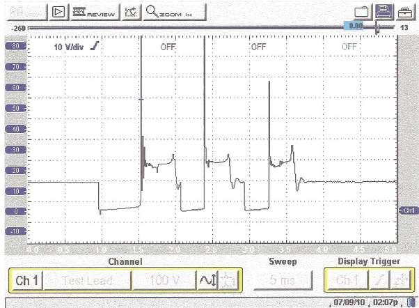
lean conditions (see Figure 3). Above 1,000 rpm the PCM will revert back to one firing event
In addition, as we all know a pattern failure misfire on the Ford Triton engines is a loss of insulation on the secondary spark plug boot causing voltage to arc to the plug well. Whenever replacing spark plugs on these engines it is always highly recommended to replace the boots and suppressor springs. These types of misfires usually occur under loaded acceleration conditions when the KV values increase as cylinder pressures increase. Also, I’m sure you have customers like mine who are waiting for the second coming to have their spark plugs replaced. On some modern Chrysler COPequipped engines the PCM will monitor the collapse time of each individual firing time (spark duration), however, the actual values are not accurate and should be used for comparison between each individual coil firing times. You can get these values from your scan tool (see Figure 4). Good spark duration periods on COP-type ignition systems will vary between 1.5 and slightly over 2 milliseconds during a park warm idle no load condition.
On Ford and Chrysler systems, using a lab scope and probing the coil negative terminal will yield a primary ignition waveform (see Figure 5). The primary and secondary waveform will mirror each other in the spark line area. The spark line characteristics we discussed earlier still apply.
Notice, however, the secondary ignition waveform voltage per division is at 1 and 2 KV while the primary ignition waveform will vary between 10 and 20 volts per division. The scope time base is at 1 millisecond per division. Also, keep in mind that the scope’s trigger level is best set just above the spark line voltage level.
If the secondary KV demand is too high from, let’s say, worn spark plugs or lean
Figure 4

Figure 5 density conditions the primary spark duration periods will be too short and lean cylinder conditions will abruptly bend the spark line voltage up during a power brake condition. On the Chrysler and Ford COP units, a secondary KV wand can be used to pick up a secondary waveform by simply laying the probe on top of the coil. Keep in mind the attenuation factor of the KV probes are 1,000 to 1. This means that if your scope is set to 1 volt per division the attenuation is now 1 KV per division. A time base of 1 ms. per division is usually ideal. The secondary KV wand can also be used on DIS secondary leads, as well.
Half the cylinders are fired at a negative polarity and the other half are fired positively. On the cylinders that are fired with negative polarity, you must use the invert function on your scope while turning it off while viewing the positively fired cylinders. By the way, all distributor-equipped engines and COP-type ignition systems fire secondary at a negative polarity, meaning that you must use the invert function of the scope. The secondary KV wand will not work on most Asian COP units because they are heavily potted causing the magnetic field to be too weak to be sensed by the COP wand. This will require a secondary lead between the coil and spark plug and using the conventional KV probe around the lead. Remember that we refer to the spark line characteristics as our electronic window inside the combustion chamber.
There are several versions of the secondary KV wand available at www.AESWAVE.com
On the GM coil near plug units found on the V-8 Vortec engines, there is a short 8.5-inch secondary lead between the coil and spark plug. The COP wand works very nicely on these systems by laying it next to the plug wire, or you can simply use the conventional secondary KV probe clamped around the plug wire. Again, the invert function must be used.
There are three different vendors that supply the coils for GM. They are Delphi, Melco and Denso. The coils are not interchangeable, but the secondary leads look identical and are not interchangeable because the resistance values vary greatly.
As we stated earlier, access to the primary side of a Ford or Chrysler can be done by back probing the negative terminal of these coils and thus viewing the primary side of the coil.
That test is not possible on the GM coil near plug units because the ignitor is integrated into each individual coil. The PCM uses low current drivers to bias (turn on) the coil current. The signal from the PCM is a 5 volt / 0 volt toggle. The rising edge to 5 volts turns primary on while the falling edge to 0 volts turns primary off causing the primary magnetic field to collapse, which is mutually inducted into secondary and multiplied to create the high secondary firing voltages needed.
A tech tip here may be needed. During KOEO we can bias these coils with a standard 12 volt test light. By picking up 12 volts with the alligator end of the test light and by piercing the ignitor control wire and momentarily touching the ignitor control wire, we will fire a 25 KV spark tester.
While we are on the subject of using a spark


tester, keep in mind that all good COP units can easily fire an ST125 spark tester. For those of you who use the adjustable spark testers, a 3/4-inch gap is very close to a 25 KV demand.
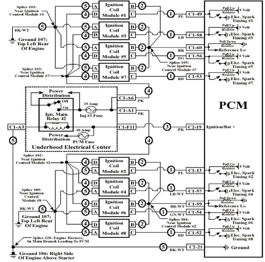
One important note here on the GM coil near plug units: The coils are powered up from a single main ignition relay and all the coils and ignitors units get their ground at one location, so don’t forget about power and grounds (see Figure 6). Your scan tool may have the ability to turn on this relay during KOEO. In addition, the PCM monitors this voltage from the ignition relay so you will have a scan tool parameter to monitor the ignition feed values from this relay.
I recently had a 4.8L come in with an intermittent miss and a P0300 MIL. The owner had previously paid a shop $1,500 to replace the plugs, coils and secondary leads — to no avail. The freeze frame data indicated a 45% addition to the short- and long-term fuel trim values.
Initially my first suspicions were from a lean density misfire, since all the cylinders on bank 1 indicated multiple live and history misfires. On my diagnostics using my secondary KV probe, I found no secondary events happening on the bank 1 cylinders. By probing the pink
power supply wire to the bank 1 coils I found no voltage.
An open circuit at the connector on top of the valve cover was the fault. A current probe clamped around this power supply pink wire would have also pinpointed the problem.
On most all Asian COP units the coils also have the ignitors integrated into them and are forward biased (turned on) by a 5 volts square waveform. As with the GM coil near plug units, the falling 5 volt to 0 volt toggle turns primary off and fires the coils. Using a COP wand in the Asian COP units does not yield a good secondary ignition waveform because the coils are so heavily potted the magnetic field is too weak to pick up. The website www.AESwave.com offers the secondary leads to marry the coils to the spark plugs, meaning you can use a secondary KV probe to view secondary in the conventional way.
Again, access to the primary side is not possible due to the ignitor integrated inside the coil. However, an amp probe clamped around the coil positive feed wire can verify good or insufficient coil saturation values.
The point here is most critical. A single cylinder misfire can easily be a bad coil, but looking at the design of the system, a control circuit issue or a bad PCM driver could also cause a loss of spark. In the real world of diagnostics, whenever a misfire problem occurs we as technicians usually rely on scan data initially. Having said that, the cardinal rule is that a single cylinder misfire from no spark will create very minor and very brief single digit fuel trim corrections while a lean density misfire from, say, a bad injector, low fuel pressure, vacuum leak or a bad MAF sensor will create double digit addition to fuel trim. Conversely speaking, a rich density misfire will create double digit negative fuel trim corrections. Also keep in mind that in most modern day systems, whenever the misfire is severe enough the PCM
will force the engine back into open loop and cut off the injector from the misfiring cylinder, which means the fuel trim values cannot be used as we explained earlier. It would be necessary to view the scan tool fuel trim parameters before the PCM forces the engine back into open loop.
A recent case study involved a 2001 Honda Odyssey that came into my shop with a misfire symptom and no MIL with no codes, not even a pending code. Since this was a non-CAN-compliant system there were no misfire test results in the Mode 6 menu. You can’t say enough about the good old “feel through the seat of your pants,” the engine was running on five cylinders!
The front coils were easy to get to so we manually disconnected one at a time and monitored the rpm drop. While disconnecting the number 4 coil we never got the rpm drop. Putting a spark tester on the number 4 coil showed no spark. Could it be a common COP failure? What about the ignitor drive signal from the PCM (see Figure 7)? You will see a 5 volt/0 volt toggle, meaning that the PCM is sending the control signal and just like the GM systems the ignitor is forward biased by the PCM. Now let’s say the ignitor signal was flat lined at 0 volts. Could the ignitor have shorted the PCM driver?
We could easily find out by unplugging the coil. The 5V ignitor control voltage is sourced at the PCM. If we get our 5 volts back then we know the ignitor has shorted the PCM control voltage. However, in this case the ignitor control signal was present and the problem was simply a bad coil. Once the coil was replaced we should still analyze the waveform (see Figure 8). Is there a noticeable lower coil saturation value on the number 4 coil?
If your answer is yes, you are correct. If the primary feed voltage is good to this coil, then the coil should be returned to the parts supplier because the coil’s amperage saturation values are significantly lower.
On the Toyota COP systems the ignitors are also integrated into the coils the same as the GM and Honda systems, so access to a
85 YEARS OF QUALITY TOOLS! RETAINING RING PLIERS
• Convertible for use on internal/ external snap rings • Cushioned grip handles • Ergonomically designed switch allows user to change between internal and external with ease without separating the pliers • Packaged in a plastic blow molded case for protection and easy use
Also available in a six piece kit or individually.
Part# 3595
NEW

Figure 7

Figure 8 primary ignition voltage waveform is not possible. However, the amp probe becomes a valuable tool to ensure good coil saturation values.
These systems are unique in the fact that the PCM uses a separate IGT (ignitor trigger control circuit) for each individual coil. The PCM also monitors each coil’s firing event by monitoring the IGF (ignition confirmation circuit). In the event of a loss of the IGF signal to the PCM, the PCM will shut down the cylinders injector. A loss of all of the IGF signals will cause the PCM to shut down all of the injectors.
The scenario you could have here is that on a no start you could have no spark and no injector pulses at the same time. We have had a case where Figure 9

a Toyota came in as a no start indicating no spark and no injector pulses. Monitoring the IGF circuit with a lab scope showed no IGF pulses at all. As we unplugged number 3 coil the IGF pulses came back and the engine started — on 5 cylinders.
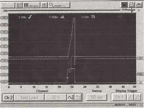
The point here is that a bad coil can pull down the IGF circuit and cause the PCM to shut down all of the injectors and disable primary on the other cylinders. Figure 9 indicates a known good representation of the Toyota COP systems showing the comparison of coil amperage saturation, IGT (trigger) and IGF (ignition confirmation) from a single cylinder firing event. The bottom trace is the IGT signal while the middle trace is the IGF signal and the upper trace is coil current using the amp probe.
Let’s look at another example of an amp probe, not only looking at good coil saturation but also how well the energy is transferred between the primary side of the coil into the secondary side.
Modern day ignition systems are known as “divorced,” meaning there is no hard-wired circuit between the primary coil windings and the secondary coil windings. There is simply an air gap. As the primary field collapses it is mutually inducted into the secondary windings across this air gap and multiplied several hundred times. Internal coil carbon tracking has a major effect on the smooth and complete transfer of this energy.
Take a look at Figure 10. At the amperage waveform’s point of primary turn off, note the erratic oscillations caused by internal coil carbon tracking. This problem can easily take out the primary coil driver in the PCM as in the Ford and Chrysler systems. We talked earlier about the use of a secondary lead between the coil and spark plug and then using our secondary KV probe around the plug wire to analyze more completely the firing and combustion event. Figure 11 shows a good secondary ignition
Moss Automotive Repair
A family business taking care of ‘family’
Moss Automotive, located in Alpharetta, Ga., was started by Danny and Charlotte Moss in 1992. Alpharetta, located about 26 miles due north of Atlanta, boasts a population of over 57,000 and is the home of famed Georgia State University. The area still maintains many historic buildings, but in recent years, it has experienced a boom in high-dollar construction, including celebrity-level multimillion dollar mansions and upscale retail complexes and ritzy condos. Once a quaint small town, Alpharetta has blossomed into an upscale area.
According to Danny and Charlotte, development has “just blown off the map,” with an influx of people who work in the Atlanta area but desire the lifestyle offered by both the small town flavor and the burgeoning vitality. Charlotte noted that the majority of well-to-do residents who now reside in town but work in Atlanta tend to have service done in the Atlanta area, closer to their work places and the expansive array of new car

Moss Automotive Repair
Alpharetta, Georgia • Owners: Danny and Charlotte Moss • Office assistant: Karla Jordan • Business founded: 1992 • Number of bays: 12 • Number of certified technicians: 2 • Shop size: 8,400 square feet • Vehicles serviced per month: 125 • Hourly labor rate: $107.78 • Average spent on tools and equipment annually: $15,000 – $20,000 • Vehicle makes serviced: Domestic and import, specializing in diagnostics • Website: www.mossautomotive.com dealerships, while Moss’s clientele primary consists of customers who both live and work in Alpharetta.
Moss Automotive Repair boasts an 8,400-squarefoot shop with 12 service bays in the town of Alpharetta, Ga., about 26 miles north of Atlanta.

The beginnings
Moss Automotive was born out of a longtime desire to open a shop that offers the highest level of quality, but there’s more to the story. Charlotte and Danny met in grade school and eventually became high school sweethearts. At age 17, Danny owned a 1965 Mustang, and decided to rebuild the worn-out engine. While he didn’t have access to a shop area at the time, Charlotte’s father offered to let Danny use his basement for the project. Upon seeing an empty block and parts scattered throughout the room, apparently Charlotte’s father shook his head and said “that engine will never run again.” Despite the pessimism, Danny finished the engine, installed it into the Mustang, and it ran like a fine watch.
During the same period, his mother’s car had a drivability issue, which he diagnosed and successfully repaired. With these prideinspiring results, Danny was hooked. He focused his efforts on bolstering his automotive skills, and subsequently worked at an area service shop for 14 years, during which time he earned ASE Master Tech certification. Before and after they got married, the couple
frequently talked about opening their own shop and working together.
The day finally came when they decided to commit to their long-time dream, and in 1992 Danny gave his notice and Charlotte quit her job at an insurance company, and Moss Automotive was born. Along the way, both of
This was truly an example of dedicated ticular attention to shop layout to maximize efficiency.
Parts purchases
We asked, “On a scale of 0 to 5, with 0 having no influence and 5 having the greatest influence, what determines your parts buying decisions?” They said:
Price............................................2
Brand name recognition ........3
Promotion in racing................0
Perceived quality......................3
Availability/time ......................3
Danny noted that the shop probably uses more OEM parts than most shops. A substantial volume of their Motorcraft and Delco parts come from Parts Authority, Weaver Distributors and Southeastern Automotive. “We have accounts with many of the local car dealerships in town. If we do choose to use
aftermarket parts, they usually come from NAPA, O’Reilly or Advance.” “Danny is a stickler for quality,” noted Charlotte. “Brands are important and he is very particular, always striving to use only the best parts available, regardless of cost. the couple’s sons, David and Kyle, worked at offer great service, as well as better pricing, the shop as well, exposing them to their father’s than buying from car dealers, with regard to hard-work ethic. ACDelco, Motorcraft, etc.”
The suppliers we use are close to our shop and people who chased the American dream and Business philosophy realized their goals. The business operated in As both Danny and Charlotte noted, “We a smaller facility for a few years before moving are a family-run business and we like to think of our business as ‘family taking care of family.’” They have always been hands-on: Danny works on vehicles and Charlotte does the service writeThe company’s customer waiting The roomy shop features multiple lifts and with the customroom is furnished to provide a excellent lighting. The owners stay abreast ers. “Having been clean and comfortable “home” of the current technology and routinely in business almost atmosphere, say the owners. update the shop with the latest equipment. 26 years, we have into the current 8,400-square-foot building, watched many of our customers’ children which Danny personally designed, with pargrow up and have families of their own,” says


ups and interacts Charlotte. “And they are still our customers.
Approach to training
Danny said, “We take advantage of all classes, training videos and manufacturer clinics that we have access to. We also subscribe to a number of OE parts and repair networks, staying up-to-date on new technology, diagnostic and repair information.” He routinely updates shop equipment hardware and software to make sure that his techs have the best tools and training to maximize diagnostic and repair performance.
How does ASP benefit your business?
Danny said, “We look forward to each issue. The technical articles are always of interest, along with up-to-date insight into new tools and equipment. Auto Service Professional is one of the ‘must read’ publications we get.”


