15 minute read
Giti reveals a 5-year plan: Two brands will benefit from U.S. plant

from Modern Tire Dealer - May 2019
by EndeavorBusinessMedia-VehicleRepairGroup

By Joy Kopcha
Giti reveals a 5-year plan
TWO BRANDS WILL BENEFIT FROM U.S. PLANT
s Giti Tire (USA) Ltd. continues to ramp up produc
Ation at its first factory in the U.S., the tire maker also is unveiling the first of three new products for 2019. And Tim Fulton, CEO of Giti North America, said this is just the beginning of a rapid-fire revelation of new tires.
“We’ve got a plan over the next five years to introduce new products every year out of this plant,” Fulton said. “This plant will help us launch new products. That will help us have a complete footprint with two brands, GT Radial and Giti.”
The company will reveal a Giti-brand passenger touring line in 2020. But first up are three new products for the GT Radial brand.
The GT Radial Maxtour LX is a grand touring tire that fits the top 20 passenger cars and crossover vehicles sold in the U.S. in 2018. Of its 42 sizes, 25 are being built at Giti’s manufacturing facility in Richburg, S.C. (The other 17 come from Giti’s plant in Indonesia.) Tire dealers began selling the Maxtour LX in April 2019.
In mid- to late-summer of 2019, Giti will launch the GT Radial Adventuro HT. Jim Mayfield, senior executive vice president of sales and marketing, said the company has begun building some sizes of the tire. Its production, like the Maxtour LX, will be split between the U.S. and Indonesia.
The third tire planned for 2019 is the GT Radial Maxmiler Pro, designed for transit vans. Mayfield said the company has begun a soft launch of the van tire. It is being built in Indonesia, and targets “a segment of the market that is under-served. We feel we’ll do very well there.
“That’s three new product lines that we’ll go to market with in 2019 to help us as we build the GT Radial brand from where we are now.”
Hank Eisenga, plant manager for Giti’s facility in Richburg, is vice president of manufacturing for Giti Tire Manufacturing (USA) Ltd.
Giti officials gathered in the storage area of the company’s South Carolina tire factory. From left, Phang Wai Yeen, Hank Eisenga, Tim Fulton and Jim Mayfield.

“The product road map is critical. And we’ve got to be ahead of the curve,” he said.
The 1.7 million square-foot plant sits on 1,600 acres in South Carolina, about halfway between Charlotte, N.C., and Columbia, S.C. Eisenga said there are more than 700 employees at work who are producing more than 8,000 tires a day. “And we’re continuing to grow.” At full capacity, the plant will produce 5 million tires a year, and after another phase of expansion and construction, capacity will be 10 million tires a year.
Giti makes the Dextero brand of tires for Walmart Inc., and has been moving production of those tires from Indonesia to the U.S. facility. (Of the Dextero DHT2’s 20 sizes, 16 sizes are made in the U.S. plant. The other four are imported into the country.)
Phang Wai Yeen is chief technology officer for Giti and head of the company’s global research and development efforts. He said, “In the U.S., most important is time to market.” Giti moved its U.S. R&D operations to South Carolina from the Akron, Ohio, area, and that work now occurs in a facility adjacent to the tire plant. He said doing that research in the U.S., where experts are able to closely track the changing needs of the domestic market, helps it respond quickly. At the same time, the company’s four R&D centers around the world work from a common technological platform so they can share products, innovations and testing results simultaneously. “We have local resources but we have global support. That is very important. We have the capability to put products into the marketplace fast.”
Fulton said Giti’s R&D capabilities set it apart, and place it in the upper echelon of tire manufacturers worldwide. “We’re the No. 11 tire manufacturer in the world. We’re amongst that top tier that has a global footprint, global R&D capabilities, a global technology platform and global distribution. It’s a big advantage.”
Dodge Journey – 2009-2018

SUBJECT VEHICLE: Dodge Journey, 2009-2018 RELEARN PROCEDURE? Yes. SPECIAL TOOLS NEEDED? Yes, a RKETPMS analyzer can be used in conjunction with a scan tool.
he tire pressure monitoring system
T(TPMS) on the 2009-2018 Chrysler/Dodge Journey monitors air pressure in the four road tires. Pressure in the spare tire is not monitored. The system alerts the driver when tire pressure falls outside predetermined thresholds. The TPMS is controlled by the wireless control module (WCM), commonly referred to as the sentry key remote entry module (SKREEM).
An indicator light located in the instrument cluster and the electronic vehicle information center (EVIC), if equipped, are used to communicate system information. The TPMS uses radio and sensor technology to monitor tire air pressure levels. Sensors, mounted to each road wheel as part of the valve stem, transmit an RF signal indicating their individual pressure to a receiver located in the SKREEM.
These transmissions occur approximately once every minute at speeds over 15 mph (24 km/h). The TPMS remains active even if no tire pressure-related message is displayed. The sensors lay dormant (Park Mode), then wake and start transmitting (Drive Mode) when the vehicle first reaches speeds over 15 mph (24 km/h). Once the wheels stop rotating for a period of approximately 20 minutes, the sensors shut down until again awakened.
Although not transmitting as when in Drive Mode, while in Park Mode, the sensors still transmit approximately once every 13 hours to let the receiver know air pressure status at that time. Sensors will also transmit when a pressure change of 1 psi (7 kPa) or more is detected during that period. Under the following conditions, the system may not function properly:
• The areas, facilities or devices that use similar radio wave frequencies are located in the vicinity of the vehicle. • A radio device of similar frequency is used near the vehicle. • A lot of snow or ice is stuck to the vehicle, especially around the wheels or wheel housings. • The battery of the sensor has been depleted (approximate 10-year life span).
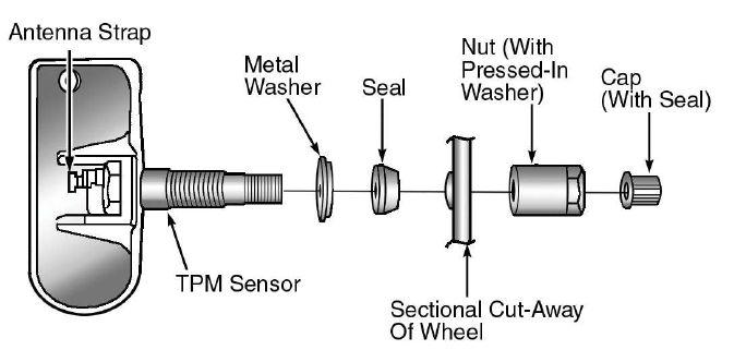
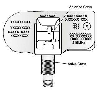
Figure 2: Identifying tire pressure sensor components (2009-10 — 2 of 2).
• A spare tire is installed. • A tire without a tire pressure sensor is used. • Wheels other than the manufacturer factory wheels are used.
TIRE PRESSURE MONITOR WARNING INDICATORS If any road tire pressure has exceeded the low or high pressure threshold, the warning light will be on continuously. If equipped with the premium system, the electronic vehicle information center (EVIC) will display a message and a single chime will sound.
The text message will indicate which tire is low, and the display will show all current tire pressures (the pressure value for the low tire will be flashing). If warning indicators are on continuously due to low pressure in one or more tires, adjust tire inflation to specification. The light will remain on until tire pressure is properly set.
After adjusting air pressure in a tire, allow approximately 2 minutes for the warning indicators to turn off. If a system fault is detected, a chime will sound, and the TPMS indicator (telltale) lamp will flash for 75 seconds, and then remain on solid. For vehicles with the premium TPMS, a “CHECK TPM SYSTEM” message will appear in the EVIC, followed by a graphic display. See the appropriate manufacturer service information.
TPMS RESET PROCEDURES NOTE: If a tire pressure sensor has been replaced, the tire pressure sensors must be retrained.
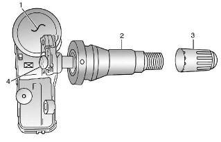
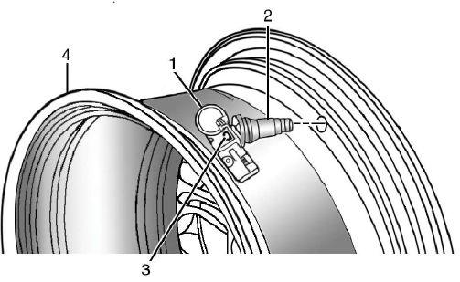
Figure 3: Identifying tire pressure sensor components (2011 and later).
TIRE PRESSURE SENSOR RETRAINING Using a RF signal, each sensor transmits tire pressure data approximately once every minute. Each sensor’s (transmitter) broadcast is uniquely coded so that the SKREEM can monitor the state of each of the sensors on the 4 rotating road wheels. The SKREEM automatically learns and stores the sensor’s ID while driving after a sensor has been replaced.
There is no formal retraining procedures necessary. Drive the vehicle for a minimum of 10 minutes while maintaining a continuous speed above 15 mph (24 km/h). During this time, the system will learn the new sensor ID code and will clear any DTCs automatically. If a sensor cannot be trained, see appropriate manufacturer service information. A new sensor ID also can be programmed directly into the WIN or TPMS module by using a RKETPMS analyzer in conjunction with a scan tool. Once the new sensor ID has been programmed, the vehicle will need to be driven above 15 mph until the fault is no longer active (lamp extinguishes) and the display is updated (for up to 20 minutes).
NOTE: Using a TPMS-RKE analyzer can take up to a minute to force a transmission from a sensor.
DEMOUNTING/MOUNTING PROCEDURES CAUTION: The tire should be demounted from the wheel using the tire changer manufacturer’s instructions. Use the following information to avoid damage during the demounting/mounting procedures.
CAUTION: The TPMS has been optimized for the original equipment tires and wheels. TPMS pressures have been established for the tire size equipped on your vehicle. Undesirable operation or
PROGRAMMABLE UNIVERSAL TPMS
99 %
VEHICLE COVERAGE
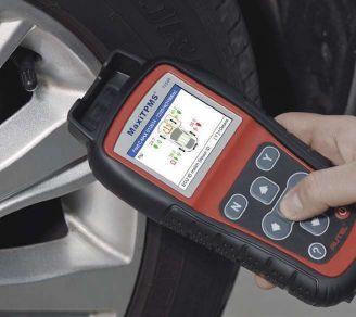
TS508
( 855 ) 288-3587 autel.com / maxitpms.com
Figure 4: Demounting the tire with a tool.
sensor damage may result when using replacement equipment that is not of the same size, type, and/or style. Aftermarket wheels can cause sensor damage.
NOTE: Wheels and tires are matchmounted at the factory. Before demounting a tire from its wheel, a reference mark should be placed on the tire at the valve stem location, to ensure that it is remounted in the original position on the wheel. For match-mounting procedures, refer to the appropriate manufacturer service information.
NOTE: Tire pressure may increase from 2 to 6 psi (14 to 41 kPa) during normal driving conditions. Do not reduce this normal pressure build up.
NOTE: If tires require leak-testing, a water test may be used to check for a leak around the sensor, as long as any water at the valve core is removed when the procedure is completed. Water can be expelled from the core area by pushing in on the core for several seconds, allowing escaping air to
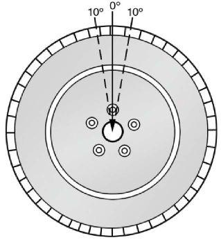
Figure 5: Removing and installing a tire pressure sensor (2009-10).
drive out any moisture. Re-inflate the tire as necessary. Install the original valve stem cap.
TIRE PRESSURE SENSOR IMPORTANT: This vehicle uses the 433 MHz TPMS sensor. Although 315 MHz and 433 MHz sensors are identical in size and shape, they are not interchangeable. Always make sure the correct sensor is being used. A RKE-TPMS analyzer can be used to determine the sensors frequency without having to demount the tire.
CAUTION: The use of tire sealants is strictly prohibited for vehicles equipped with TPMS. Tire sealants can clog tire pressure sensors.
CAUTION: Before installing a tire pressure sensor, ensure you have the correct sensor. Sensors can be easily identified by a white outline oval (with black center) insignia on the sensor body.
CAUTION: To prevent moisture and contamination from entering the valve stem, the cap used on this valve stem contains an O-ring seal. Retain the original valve stem cap for reuse. A regular valve stem cap cannot be used as a substitute. After inspecting or adjusting the tire pressure, always reinstall the valve stem cap. This will prevent moisture and dirt entry into the valve stem, which could damage the tire pressure sensor.
CAUTION: The valve stem used on this vehicle is made from aluminum, and the core is nickel-plated brass. Retain the original valve stem core for reinstallation. Do not substitute a valve stem made of a different material, as the different metals will cause corrosion.
CAUTION: 2009-10: Any time a sensor is to be reinstalled in a wheel, a new seal and washer must be installed on the stem to ensure airtight sealing (see Figure 1). 2011 and later:
Any time a sensor is to be reinstalled in a wheel, a new valve stem assembly (2) must be installed to ensure air tight sealing (see Figure 3).
CAUTION: Do not reuse the sensorto-wheel grommet. Always use a new grommet when installing a pressure sensor and properly torque the sensor nut.
Removal
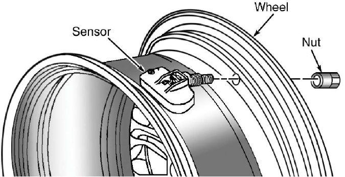
1) Remove the tire and wheel assembly from the vehicle. 2) Demount the tire from the wheel following the tire changer manufacturer’s instructions while paying special attention to the following to avoid damaging the pressure sensor: • When breaking the tire bead loose from the wheel rim, avoid using the bead breaker in the area of the sensor. That includes both front and rear beads of the tire (see Figure 4). • When preparing to demount the tire from the wheel, carefully insert the mounting/demounting tool at the valve stem +/- 10 degrees, and then proceed to demount the tire from the wheel. Use this process on both the upper and lower tire beads. 3) Using a thin-walled socket, remove the special nut retaining sensor from the wheel. While removing the nut, hold pressure against the rear of the metal valve stem to keep the valve stem from pushing rearward, which could damage the antenna strap (see Figure 2). 4) Remove the sensor (see Figure 5).
Installation
NOTE: Before reinstalling an existing tire pressure sensor, replace the seal and the metal washer at the base of the valve stem to ensure proper sealing (see Figure 1). 1) Wipe the area clean around the sensor/valve stem mounting hole in the wheel. Make sure the surface of the wheel is not damaged.
CAUTION: To avoid damaging the sensor antenna strap, hold pressure against the rear of the metal valve stem while the sensor is inserted through the wheel mounting hole and the nut is installed (see Figures. 2 and 5).
2) Insert the sensor through the wheel as shown keeping pressure against the rear of the metal valve stem.
The potted side of the sensor is to be positioned toward the wheel. Do not attempt to mount the sensor otherwise, or damage may occur.
Install the sensor nut (with a pressed-in washer) by hand (see Figures 5 and 7).
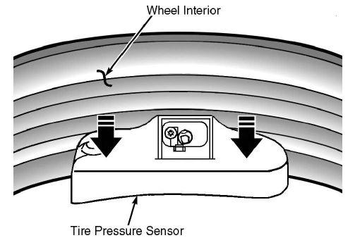
NOTE: Before tightening the sensor nut, push downward on the sensor housing in an attempt to make it flush with the interior contour of the wheel. 3) Using a thin-walled socket, install the sensor nut. While holding the sensor in position, tighten the sensor nut to 71 in.-lbs. (8 N.m).
CAUTION: Over-torqueing the sensor nut by as little as 106 in.-lbs. (12 N.m) may result in sensor separation from the valve stem. Under this condition, the sensor may still function; however, the condition should be corrected immediately. 4) Mount the tire on the wheel following the tire changer manufacturer’s instructions, paying special attention to the following to avoid damaging the tire pressure sensor:
Rotating wheel tire changers
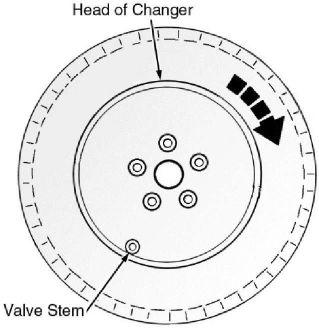
Once the wheel is mounted to the changer, position the sensor valve stem approximately 210 degrees from the head of the changer in a clockwise direction before rotating the wheel (also in a clockwise direction) to mount the tire. Use this procedure on both the upper and lower tire beads (see Figure 8).
Rotating tool tire changers
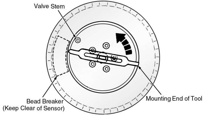
Position the wheel on the changer so that the sensor valve stem is approximately 210 degrees from the head of the changer in a clockwise direction from the mounting end of the tool (see Figure 9). Make
Figure 8: Mounting a tire using a rotating wheel machine.
sure the sensor is clear of the lower bead breaker area to avoid damaging the sensor when the breaker rises. Rotate the tool in a counterclockwise direction to mount the tire. Use this procedure on both the upper and lower tire beads. 5) Adjust air pressure to specification. Make sure the original style valve stem cap is securely installed to keep moisture out of the sensor. Install the wheel and tire assembly on the vehicle. 6) Drive the vehicle for a minimum of 10 minutes while maintaining a continuous speed above 15 mph (24 km/h). During this time, the system will learn the new sensor ID code and will clear any DTCs automatically.
If a sensor cannot be trained, see the appropriate manufacturer service information.
Information for this column comes from the tire pressure monitoring systems data in ProDemand®, Mitchell 1’s auto repair information software for domestic and import vehicles. Headquartered in Poway, Calif., Mitchell 1 has provided quality repair information solutions to the automotive industry since 1918. For more information, visit www.mitchell1.com.
Torque specifications
Component Wheel nut
Tire pressure sensor nut Torx screw Ft.-lbs. 100 In.-lbs. 171 12 (N.m) (135) (N.m) (8) (1.4)
Over-torquing the sensor nut by as little as 106 in.-lbs. (12 N.m) may result in sensor separation from the valve stem. Under this condition, the sensor may still function; however, the condition should be corrected immediately.