17 minute read
performance dynamics

from Modern Tire Dealer - Performance Handbook 2015
by EndeavorBusinessMedia-VehicleRepairGroup
The impact of plus-sizing on vehicle performance dynamics
By Wayne Williams
Is bigger better? Does a wider footprint always translate into better handling?
Every day, cons u m e r s ask retail tire dealers these questions:
• “Will plus-sizing my vehicle’s tires make my car handle better?” • “Will I get better traction?” • “Will that give me a harder ride?”
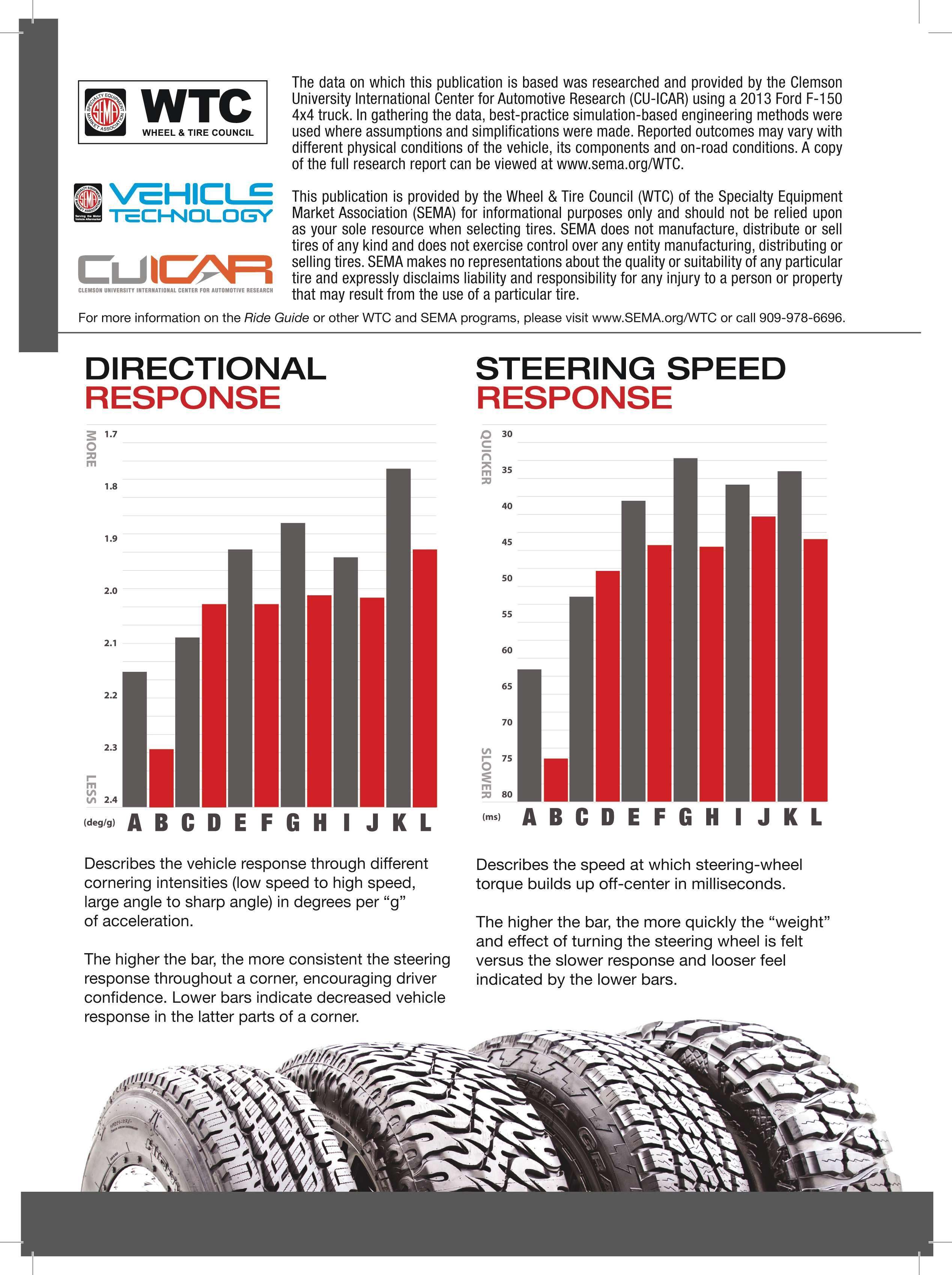
The Specialty Equipment Market Association (SEMA) Wheel & Tire Council (WTC) and Clemson University’s International Center for Automotive Research (CU-ICAR) together set out to understand the effects of plus-sizing — the dynamics associated with the changing of wheels, offsets, tire sidewall heights, wheel diameters and other associated modifcations.
The quest was to specifcally and scientifcally understand vehicle handling dynamics related to the customization of wheels and tires.
Test subject
The researchers selected a frequently modified vehicle — Am e rica’s t op - s ellin g truck, the Ford F-150. After months of testing and evaluation at CU-ICAR’s Greenville, S.C., campus, the results were very interesting. Though they supported long-standing industry beliefs, the specifcs were eye opening.
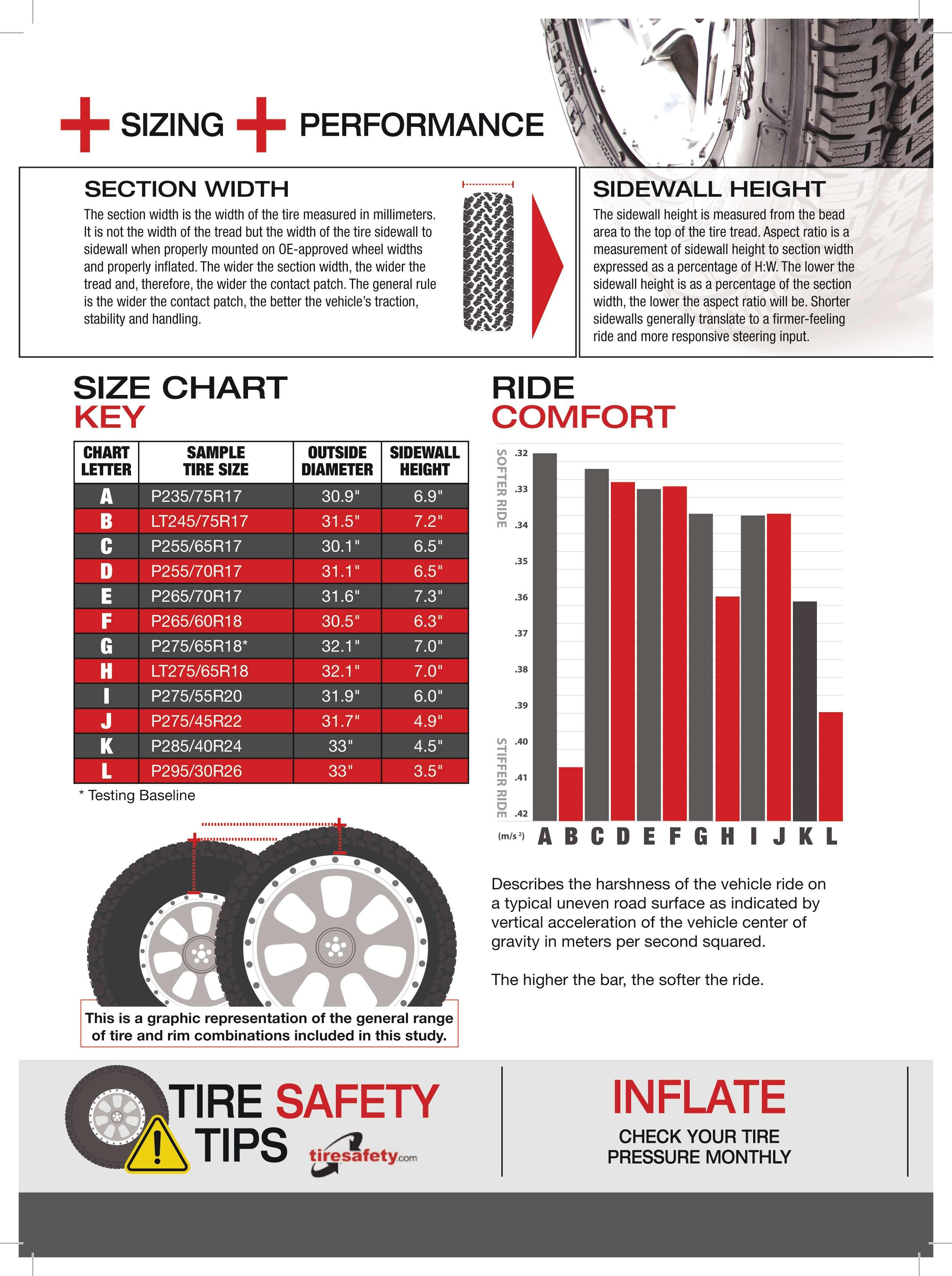
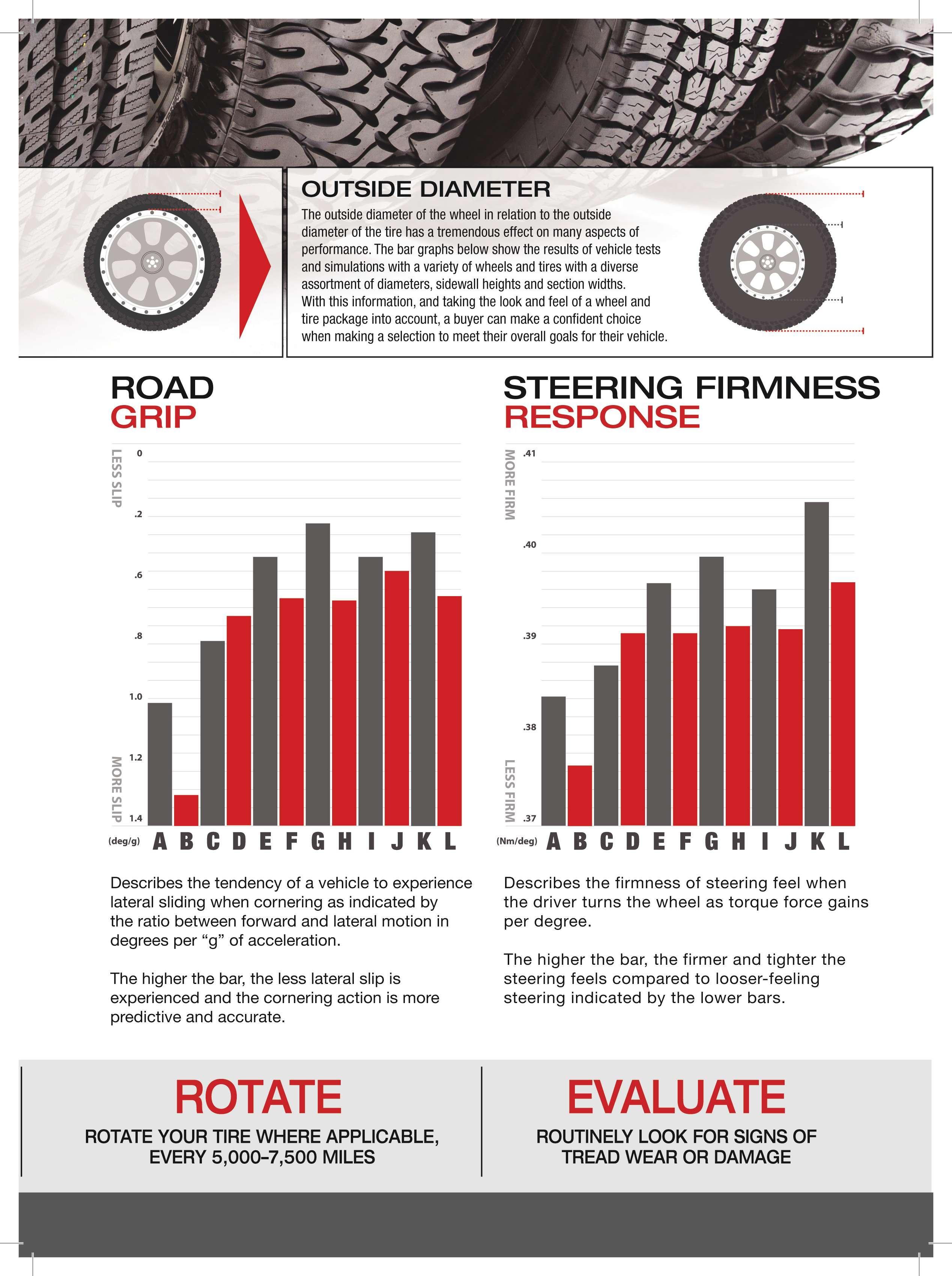
In many cases, shorter sidewalls did not translate into a harsher ride. The difference in harshness was less than generally understood and much less than anticipated.
The facts support the idea that customers can have it all — better handling, better directional response, better steering response, better steering frmness and road grip — without sacrifcing ride comfort.
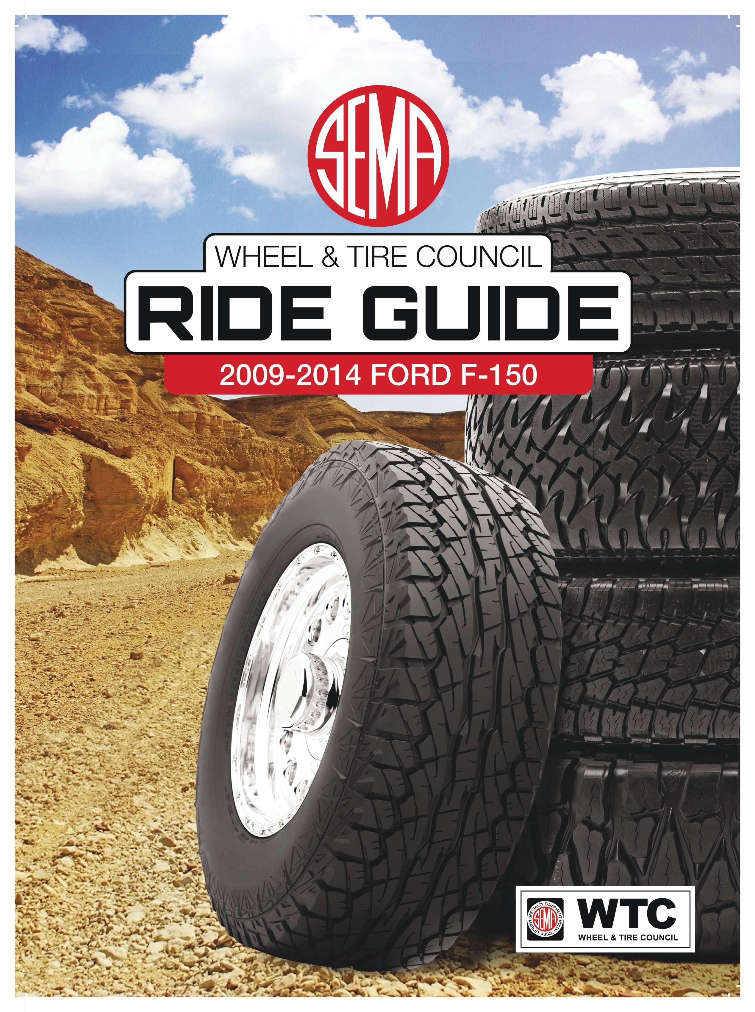
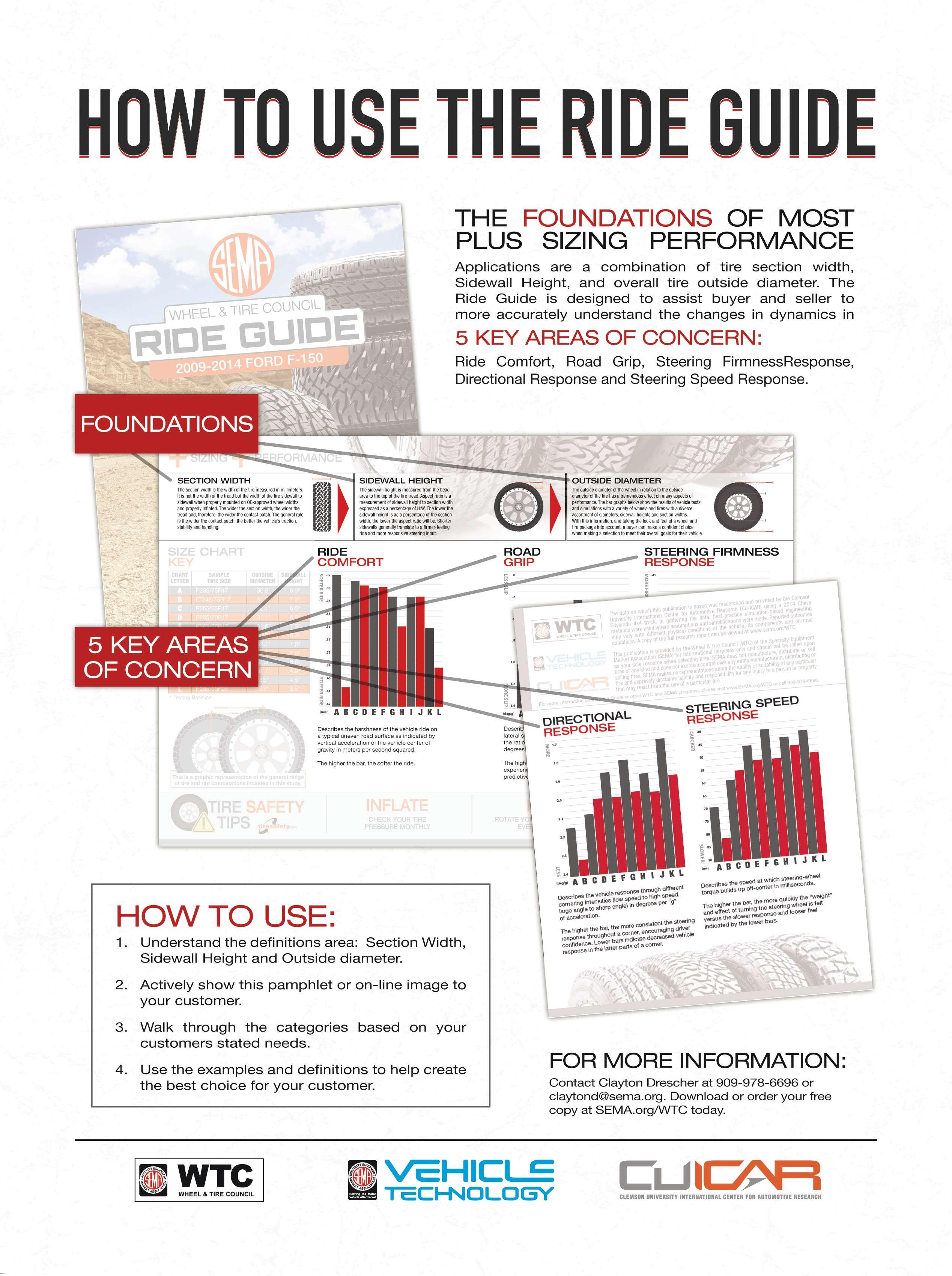
Upon receipt of the scientifc data, the team at WTC reformatted the data into a usable and understandable format that is consumer-friendly and named it the Ride Guide.
The Ride Guide outlines the basics o f plus -sizing, section width, sidewall height and outside diameter, but more importantly, it specifically describes the individual results in a bar graph that is more accurate and predictive of fnal dynamics after a vehicle wheel and tire modifcation is completed.
The Ride Guide is just that, a guide that assists aftermarket providers in setting and realizing customer expectations.
Now sales associates can give consumers a defnitive answer to their most common question: “Can you tell me before I spend my money how tire and wheel plus-sizing is going to affect the ride quality and handling of my vehicle?”
Since the initial testing of the 2013 Ford F-150, CU-ICAR has tested the 2014 Chevrolet Silverado with similar fndings, and they’re just wrapping up results on the 2014 Mazda3. The next target market is the wildly popular American muscle car segment with the frst scheduled testing of the new Ford Mustang.
In today’s digital marketplace, information is easily accessible; however, good, reliable and professional information, not so much. The victory goes to the prepared
Those dealerships that deliver the best solutions, the most professional answers and have the ability to master the total customer experience will win both the customer and the business.
A copy of the Ride Guide is available through these sources: SEMA at www.sema.org and the WTC at www.sema.org/wtc.
...Continued from page 16 uniformity and concentric bead seating. You can check to see if the beads are concentri
The easy way to mount an SUV tire and wheel assembly on a balancer is to use the front cup and back cone method, but that doesn’t guarantee the best possible balance.
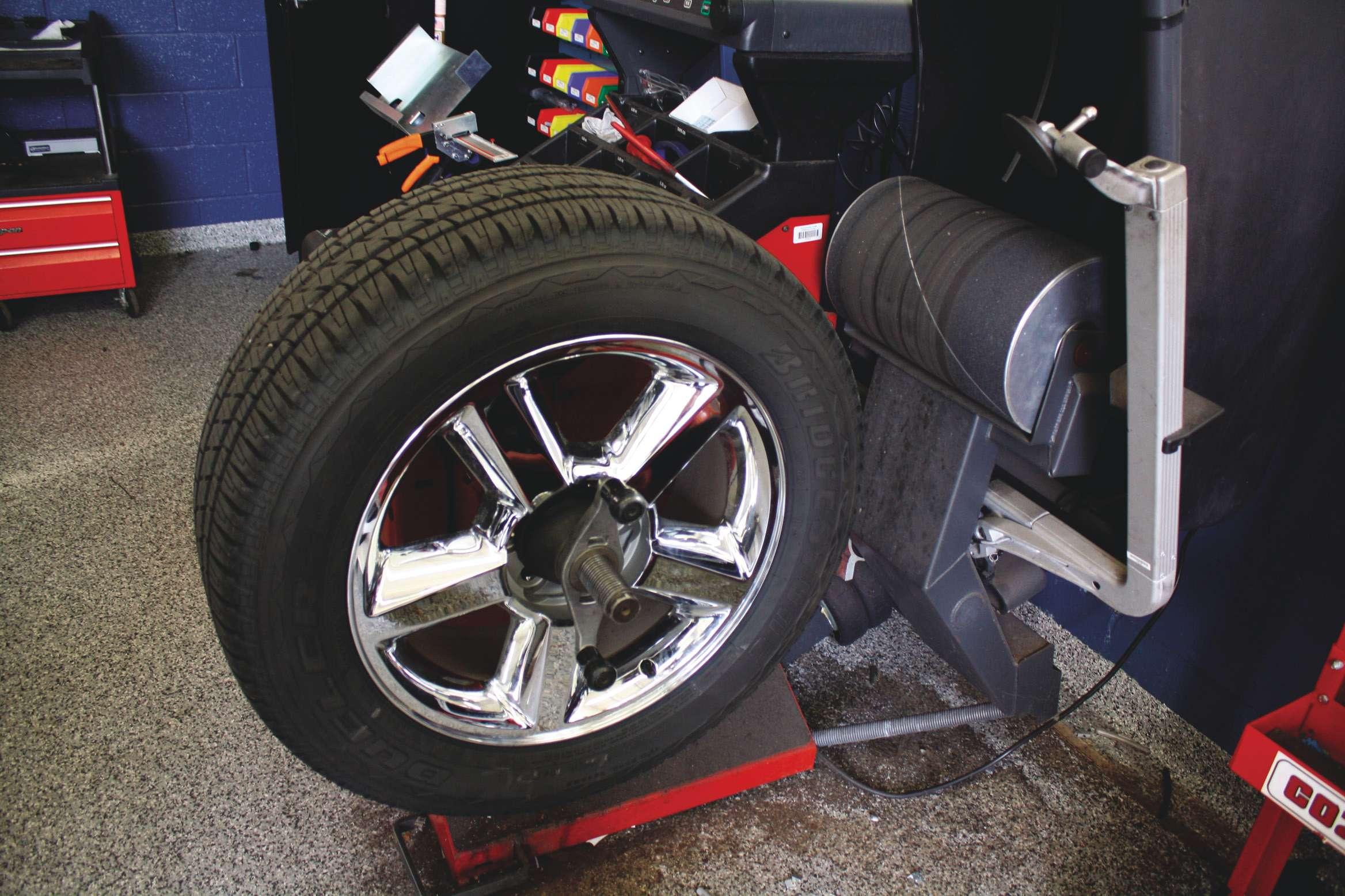
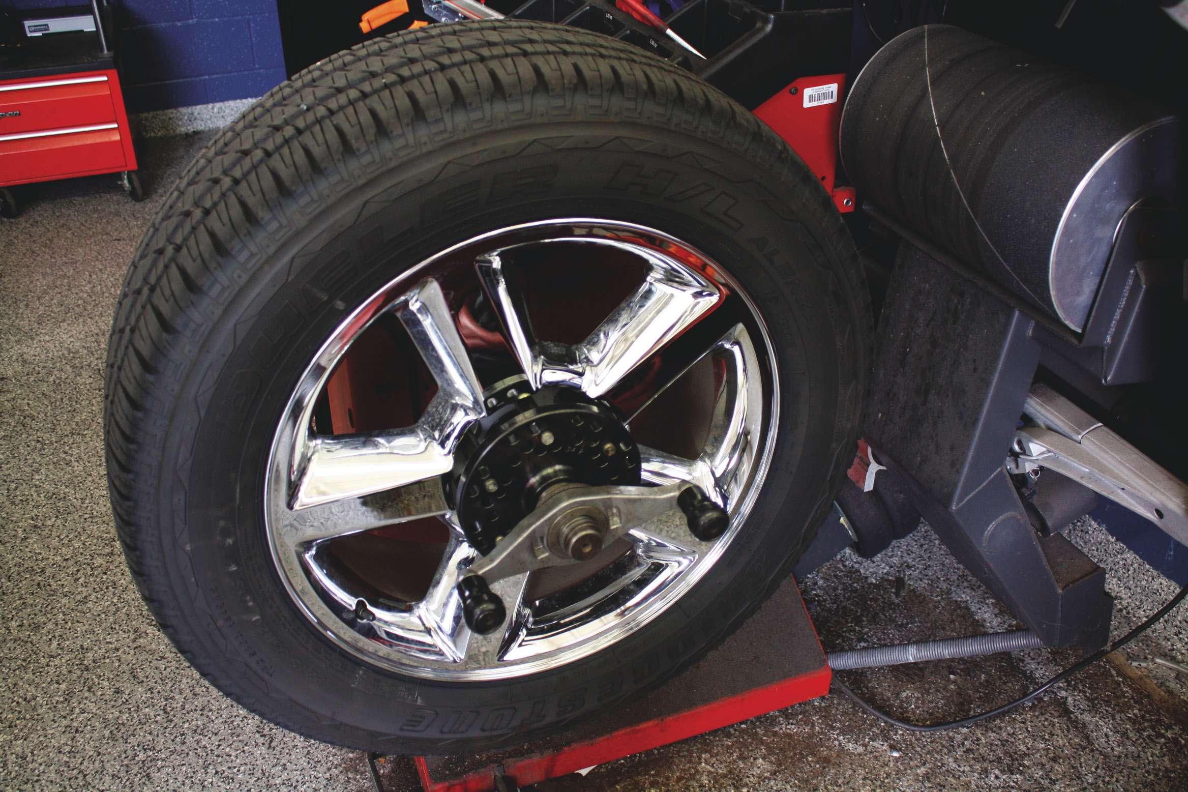
This method takes a little more time to set the pin positions, but ultimately the quality of the balance is much better when service technicians use the pin plate.
The pin plate creates a more accurate and centered position on the shaft of the balancer by using the bolt holes and the center bore to mount the assembly on the balancer. cally seated by measuring the distance between the rim fange edge and the molded ribs on the lower sidewall. According to industry recommendations, there cannot be more than 2/32 of an inch variation in that distance. Personally, I believe that any variation in the distance between the rim fange and the molded ribs is unacceptable, especially when mounting performance tires that will be installed on vehicles with more highly tuned suspension systems. It doesn’t always take a lot of imbalance for the driver to notice that something is wrong, so making sure the tire is centered on the rim must be the frst step.
The next step is a combination of technology and training. Modern tire balancing machines have advanced diagnostic and runout measurement capabilities. They are capable of matching the high spot of the tire with the low spot of the rim to ensure the best uniformity of the rotating assembly. They can even make recommendations on where the tires should be installed on the vehicle for the best ride.
Again, the performance customer is expecting a lot more when it comes to ride and handling, so having the capability to match-mount tires is often necessary.
In the case of the economy car driver who is forced into a performance tire purchase, it might not be critical. But the true performance car driver of a performance automobile is unwilling to accept anything less than perfection. And for the SUV owner who spends upward of $200 per tire, even the slightest vibration is unacceptable, so taking the extra steps to ensure the balance is as good as possible is just good business.
But all the advanced balancing technology on the planet is worthless in the hands of a technician who is not trained to utilize the features on the machine. Too many retailers go out and spend tens of thousands of dollars on the latest and greatest balancers only to watch technicians set the machine to static because they don’t know how to use tape weights. And while the technology is there to make sure the larger SUV and light truck tires are as balanced as they can be, poorly trained and unmotivated employees continue to take the easy route resulting in costly comebacks and potentially bad reviews on the dreaded Internet. If I’m spending almost $1,000 on a set of performance tires, I expect a lot more than a basic static/dynamic balance.
Maybe the solution is to offer different levels of tire balancing. For customers who are primarily interested in saving money, the simple static and dynamic balance is the way to go (and possibly included in the price of the tire.)
On the other hand, the performance or SUV customer might see the value in paying a little more for advanced balancing technology.
Of course, that means the salesperson has to sell the value related to a match-mount, roadforce, laser-guided tire balance. Premium tire balancing services can be marketed and sold in a way that makes it worth the investment to train technicians to effectively use all of the available technology to achieve the best possible balance.
The fnal step of performance tire balancing in a performance world is to invest in a set of pin-plate adaptors. It doesn’t make much sense to install the assembly on the balancer with the standard front cap and back cone when balancing performance tires, unless of course the technician is going to slap a weight on the back fange for a static balance.
If you are going to the trouble of utilizing all of the available technology, then it only makes sense that the tire is perfectly centered on the machine. And while the back cone front cap
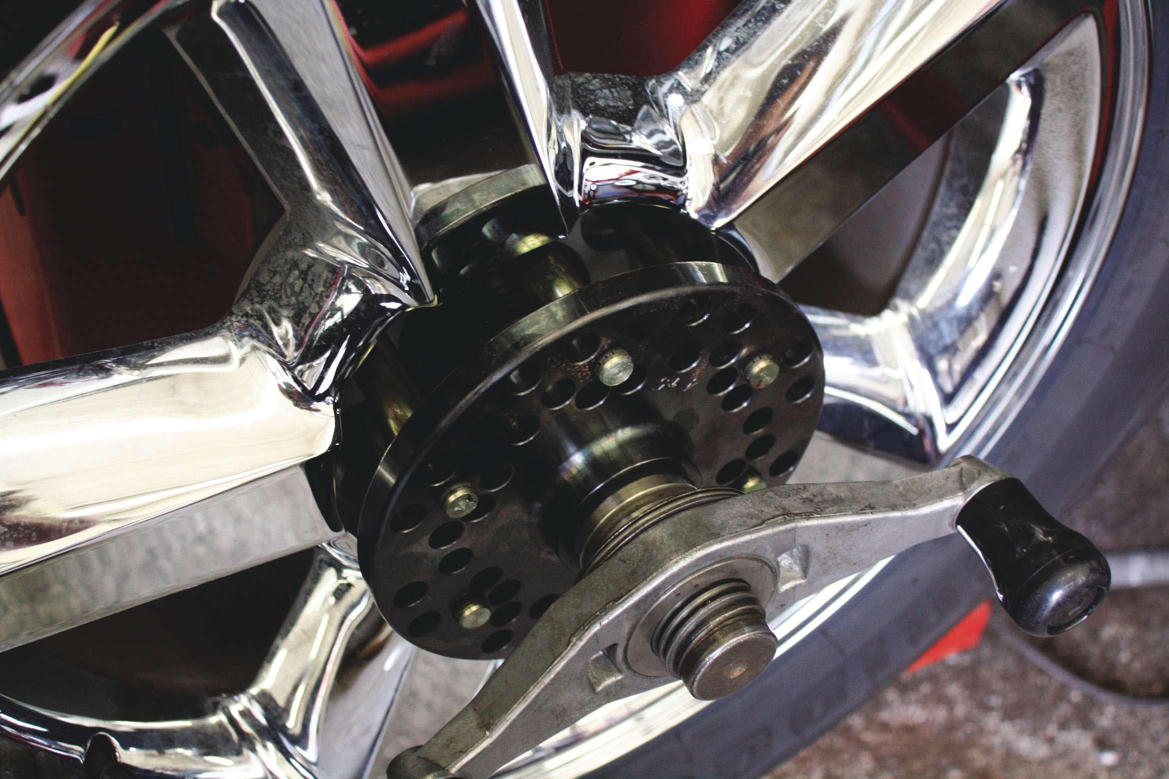
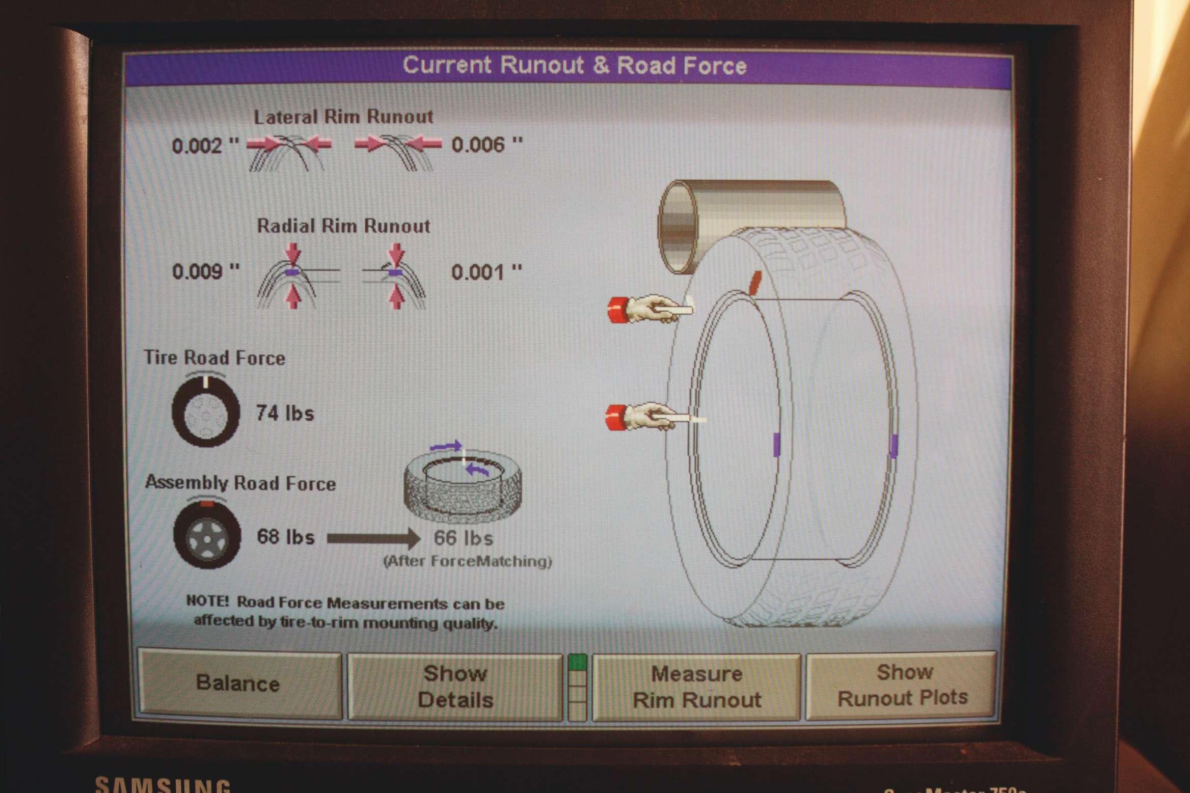
method is capable of achieving some level of precision, the pin plate method has been proven as the most accurate method for securing and centering the assembly.
When the V-rated performance tire and wheel assembly was mounted on the balancer using the front cup and back cone method, the road force balancer detected 66 pounds of road force after force matching.
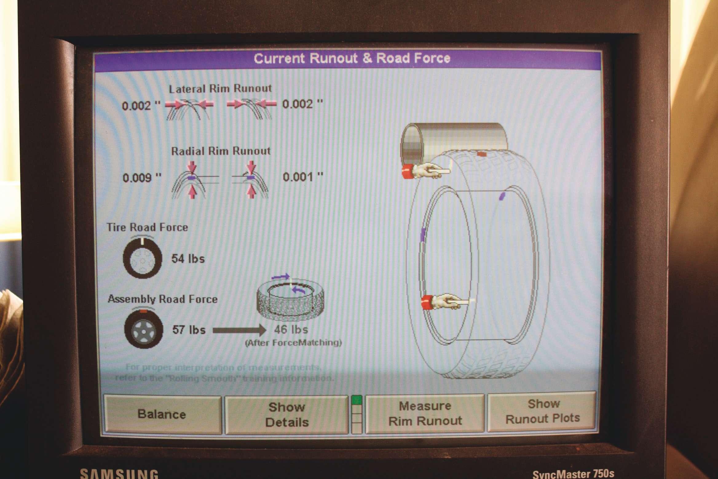
As you can see, using the pin plate and back cone on the same assembly didn’t result in signifcant improvement in the lateral and radial rim runout, but it would reduce the road force to 46 pounds after force matching.
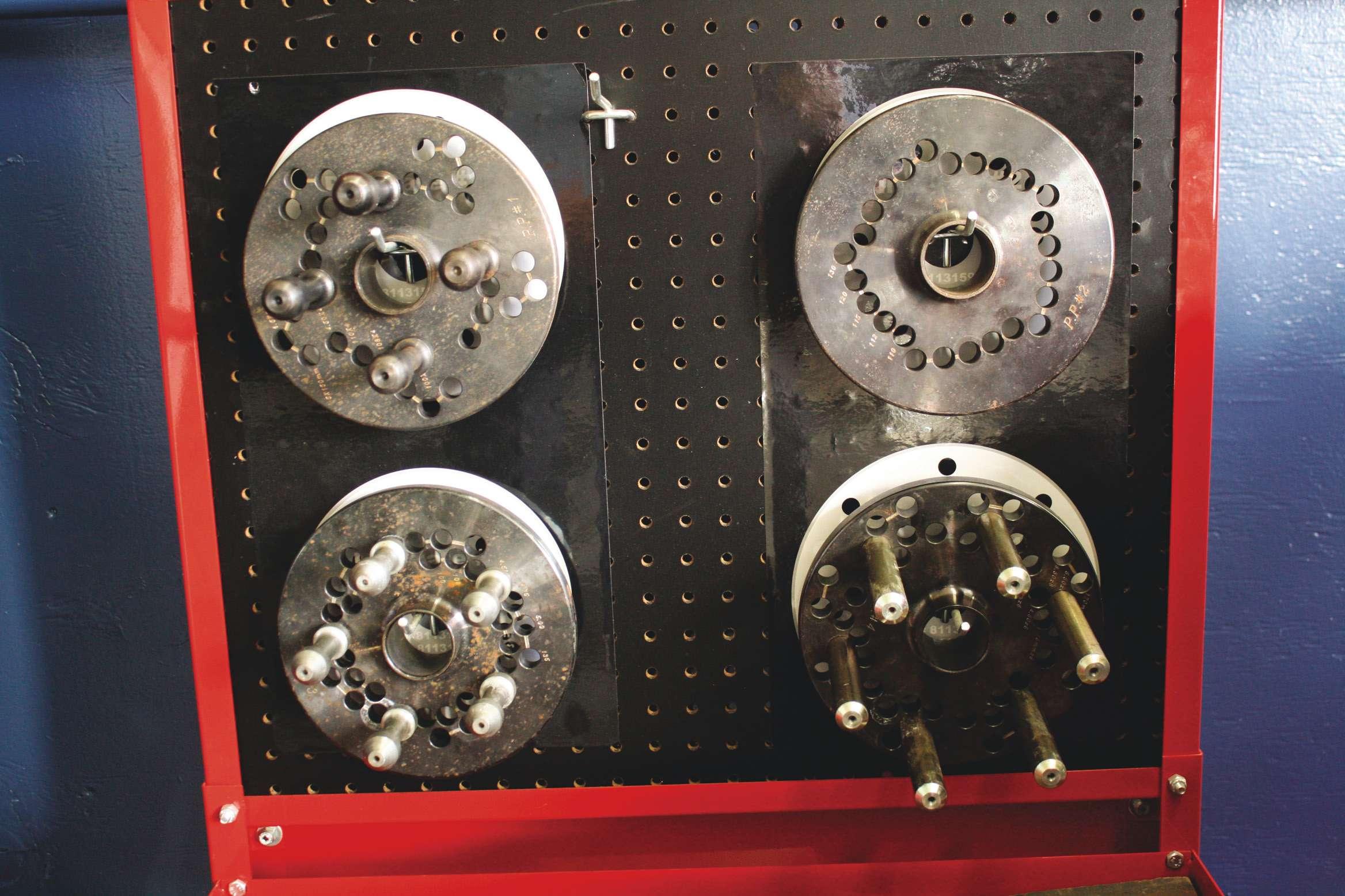
Front caps vs. pin plates
In order to demonstrate the difference between front caps and pin plates, I conducted a brief test at a local community college. In the frst test, I balanced a V-rated P255/45R18 V-rated performance tire on an alloy rim using the front cap and rear cone method. The machine that I used was capable of measuring road force, so I completed the necessary checks and measurements in order to determine how much was present. Tire road force was 74 pounds and assembly force was 68 pounds. After force matching, it could be improved to 66 pounds. When balancing the same assembly using the pin plate, the amount of tire road force improved to 54 pounds while the assembly improved to 57 pounds. After force matching, the road force would improve to 46 pounds.
It’s important to remember that nothing changed between the two balancing attempts. It was the same tire with the same settings and the only difference was the method for attaching it to the machine. In this instance, the pin plate would result in less weight being applied and a potentially better balance.
The second test involved a P275/55R20 that was installed on an SUV. Using the front cap, back cone attachment method, the tire road force was 25 pounds and the assembly road force was 26 pounds. After force matching, it would improve to 23 pounds. But the important thing to recognize is the runout measurements. Lateral runout was 0.029 inches on the inner fange and 0.024 inches on the outer. The radial runout was 0.018 inches on the inner flange and 0.015 inches on the outer. When the assembly was attached to the balancer using the pin plate, the differences in road force were minimal, 24 pounds for the tire and 23 for the assembly with an improvement to 22 pounds after force matching. But the runout measurements improved to 0.003 inches and 0.004 inches for lateral with 0.005 inches and 0.007 inches for radial runout.
These tests do not endorse road force or force matching. They are just intended to demonstrate the positive impact that pin plates have on balance and runout measurement. Performance tires and SUV tires with performance expectations will deliver a better ride after balancing simply because they are more uniformly secured to the machine.
This allows the technology in any balancer to be more accurate because the properties being measured are more precise.
A changing landscape
Clearly, the landscape of the replacement tire market is evolving to include more performance tires on vehicles that also are becoming more performance-oriented. And with tire prices for SUV drivers steadily climbing, customers who spend almost $1,000 for a set of four expect a higher level of vehicle performance. Balancing those tires can be accomplished a variety of different ways, but advanced balancers can achieve an unmatched level of uniformity if the features are fully utilized. In order for that to happen, technicians must be properly trained and have access to the proper equipment, like pin plates.
Customer expectations in a performance world are signifcantly higher. Since a growing number of them are more or less forced into a performance tire purchase, the margin of error when it comes to balance is as narrow as it has ever been in the history of the tire industry.
Performance tires are guaranteed to perform to some degree, but reaching their full potential depends on balancing practices that live up the defnition.

Wheel fasteners
Understanding the nuts and bolts of wheel clamping
By Mike Mavrigian Photos by author unless otherwise noted.
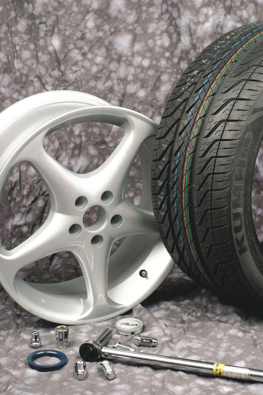
Wheel fasteners are arguably the most important components on any vehicle, responsible for securing the wheels to the vehicle, yet are often the
least understood and appreciated. This brief article offers a basic overview of the often overlooked threaded wheel fastener — how to identify it and how to handle it. This includes information dealing with fastener thread size, seat styles and torque values. Our goal is to provide clear and accurate explanations of various wheel fastening systems that will help installers select the correct type of fastener for a given application.
NOTE: The common method of attaching a wheel to a hub involves a group of individual threaded wheel fasteners (wheel nuts or wheel bolts), involving a pattern of four, fve, six or eight fasteners per wheel. Another type of wheel clamping system involves attaching the wheel to the hub with a single spindle nut. This is most commonly referred to as a knock-off or pin-drive system.
Wheel fastener seat styles
Identifying and matching fastener seat styles is absolutely critical. The “seat” refers to the contact area between the base of the fastener head and the wheel’s fastener pocket. Although variations exist, three basic seat styles are in common use today. These include conical, radius and fat-seat types.
Conical wheel nuts (or wheel bolts) feature a straight taper at the seat area. Conical fasteners are also called “tapered” or “cone” types. All three names refer to the same style. This type of taper is created most commonly in a 60-degree angle.
Radius seats are also called “ball” or “rounded” seats. As the name implies, the seat features a radiused “ball” shape that nestles into a ball-shaped pocket in the wheel. Many European vehicles such as Porsche and Mercedes use radius seat styles, in either nut or bolt applications.
The fat seat style is most often called a “mag” style (the term “mag” doesn’t imply anything in terms of geometric shape, it’s simply a slang carryover from the early days of the American performance scene when race wheels were cast magnesium, and commonly used a flat seat because it was easier and cheaper to produce a round hole in a fat hub center area. As we all know, the unfortunate misnomer “mag” has stuck with us as a catch-call to denote any custom wheel, whether it’s made of magnesium, aluminum or other alloys). Mag style (fat seat) nuts generally feature a smooth shank extension under the head, used to center the wheel and to provide needed thread engagement depth.
Never mix seat styles! If a wheel is designed for conical 60-degree seats, the only fastener seat style that can be used is a 60-degree conical type. The same rule applies for radius and fat seat styles. Only use the correct seat style of fastener for the seat style of the given wheel. Using the incorrect seat style can, and likely will, result in fastener loosening, wheel damage, and potential tragedy due to loss of vehicle control when the wheel wobbles or separates from the vehicle. It’s simply impossible to overemphasize this point. The wheel fasteners are the only connection between the vehicle and the wheels. Without proper fastening, you’re firting with disaster.
The three most important elements of wheel fastening are:
2. Correct thread size (diameter, pitch, length). 3. Proper clamping (torque) value.
Thread engagement
Aside from selecting the proper seat style for the wheels at hand, another consideration is thread engagement. In other words, how far the nut travels over the stud, or how far the wheel bolt travels inside the hub’s threaded hole.
The rule of thumb whenever discussing threaded fastener engagement is to achieve a minimum engagement length that is equal to the diameter of the fastener’s threads. For instance, if the stud or bolt shank is 1 inch in diameter, the nut (or bolt) must engage its threads by at least 1 inch. This provides the minimal theo
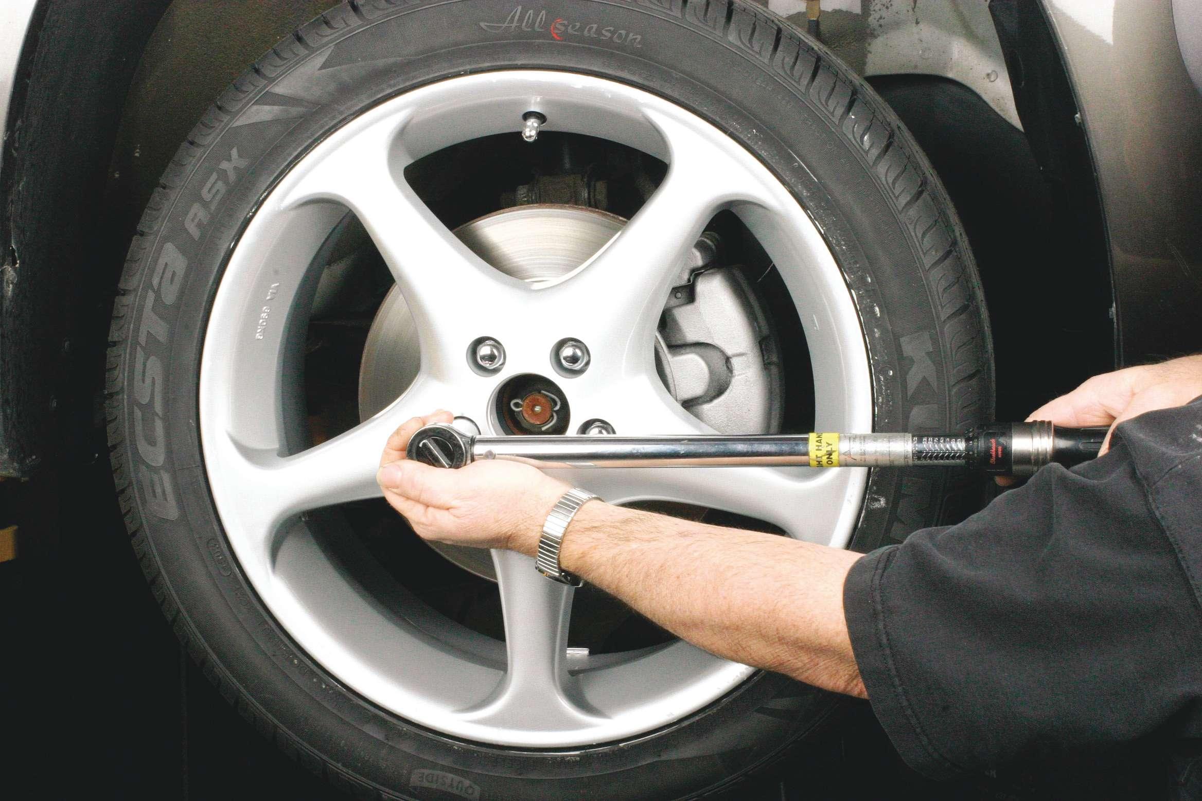
When tightening a wheel fastener, secure the wrench head with one hand to stabilize the tool, and maintain socket wrench alignment. This will aid in achieving accurate tightening. retical engagement for proper clamping load. However, the industry usually takes advantage of greater thread engagement depth, for added safety (the deeper the threads engage, the longer it takes to actually loosen the fastener; and in some cases, longer studs are used simply to aid in wheel installation onto the hub).
Thread size
Thread sizing is not diffcult to understand. The problem is that
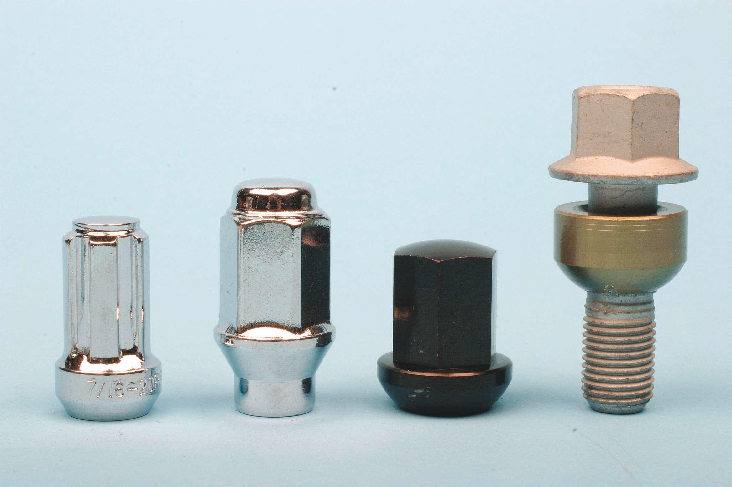
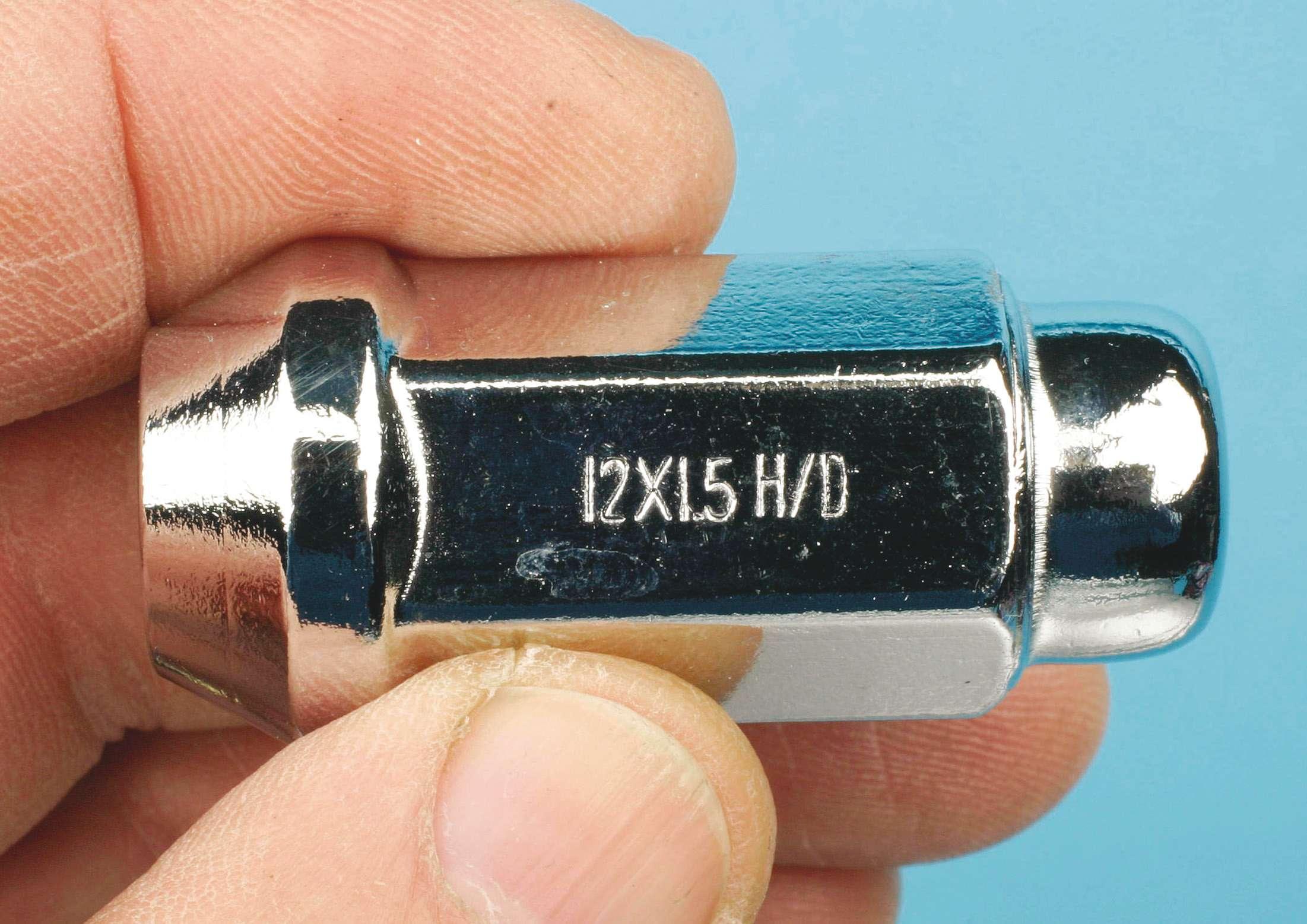
Shown here are four examples of wheel fasteners. From left: Splinedrive nut with a conical (tapered) seat; hex drive nut with conical seat and extension to accommodate thick alloy wheel; radiused (ball type) hex drive nut; and a wheel bolt that features a ball type radiused seat. most people won’t take the time to learn this very basic theory. Whether inch or metric, we need to know the diameter, the thread pitch and the thread length. For example, when dealing in an inch format, a nut identifed as a 1 x 20 x 1 indicates that the thread diameter (the diameter of the stud it will accept) is 1-inch. The number “20” indicates thread pitch. That refers to the number of threads that exist per inch of length. In this case, the thread count, or “pitch” is 20 threads-per-inch. The fnal number refers to the length of the thread engagement. The number “1” means that the nut features 1 inch of internal thread engagement length.
If the fastener is metric, diameter is represented in millimeters, pitch represents the distance from one thread to the next thread, and thread or shank length is represented in millimeters. For example, a 14 x 1.5 x 70 wheel bolt would indicate a 14 mm diameter, a 1.5 thread pitch and a thread or shank length of 70 mm.
In terms of thread pitch, it’s really very simple: With inchformat, the larger the number, the “finer” the threads (20 threads per inch would mean more threads within a given area than, say, 16 threads per inch). If the format is metric, the larger the number, the more “coarse” the threads would be (a distance of 1mm between threads would result in a greater number of threads in the same area as, say a distance of 1.75
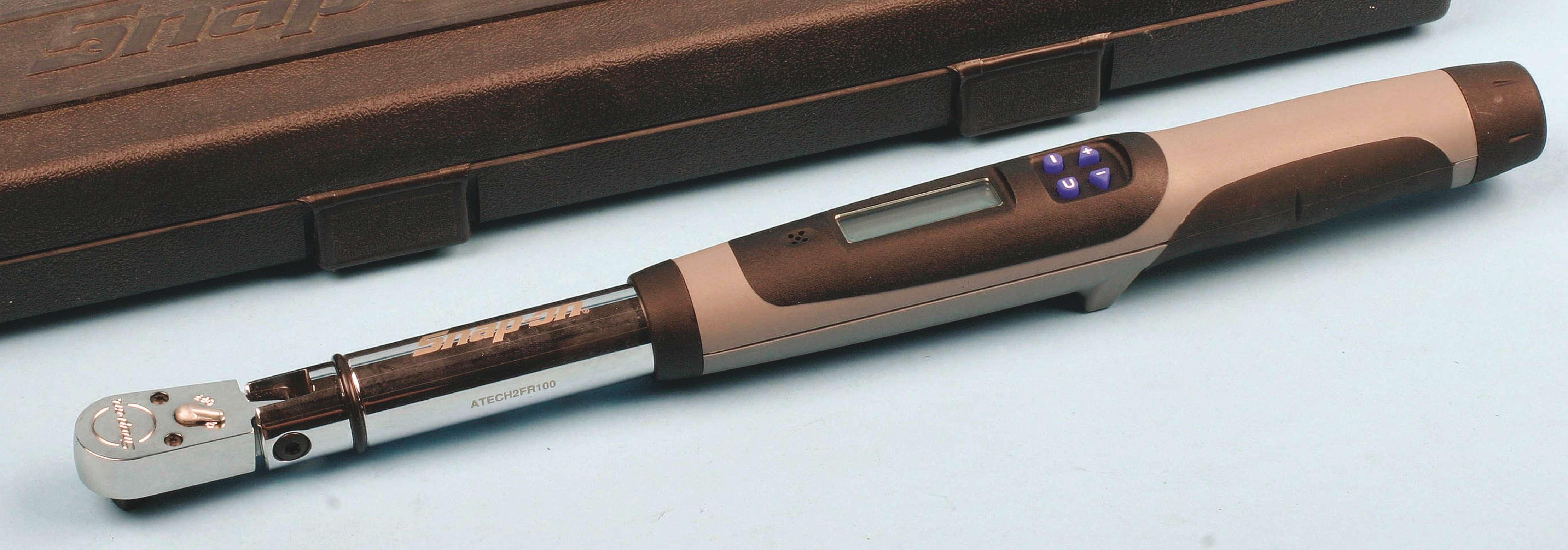
Today’s handy, high-precision digital torque wrenches offer quick value adjustment and provide audible and visual alerts (in the form of beeps and illumination) when the desired value is reached.
mm between threads). So, in inch format, smaller pitch numbers mean “coarse” threads, while larger numbers indicate “fner” threads. In metric format, small numbers indicate fner threads, while larger numbers indicate more “coarse” thread. Many people tend to make this issue more confusing than it really is. Simply think about what the number means (number of threads per inch if the fastener is inch-type; or distance between threads, if the fastener is metric type).
If we were referring to a bolt, both diameter and pitch are determined the same way. Length would then refer to the shank length (the length of the bolt under the head), or in the case of wheel bolts, the length of the bolt from the bottom of the seat to the tip of the threaded end.
In order to accurately identify the thread diameter, pitch and length of any wheel fastener, you can handle this by obtaining a total of three readily-available tools: a combination bolt/nut sizing card (these
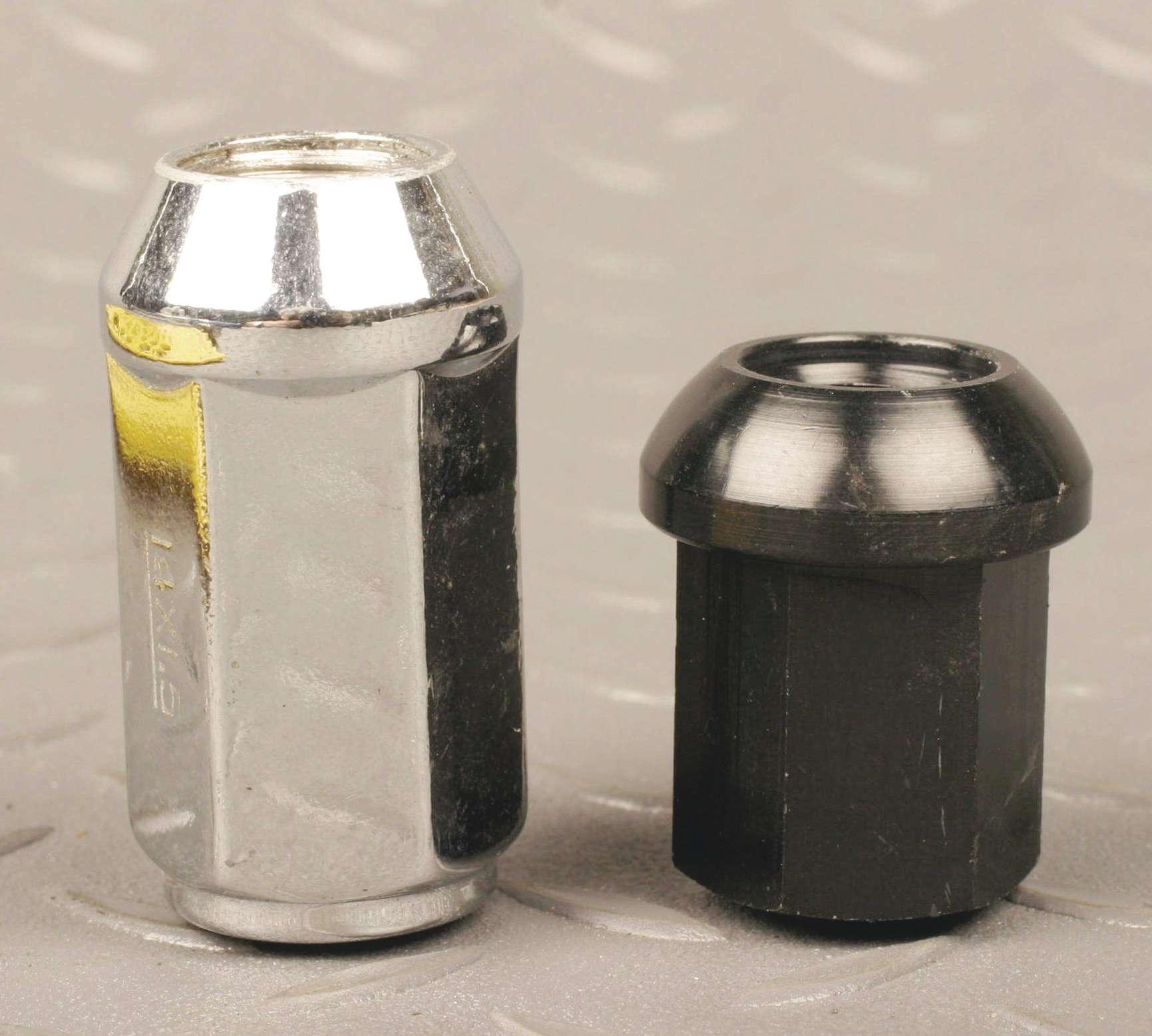
Here are examples of conical (on the left) and radius wheel nut seats.
