IM NAILING
a
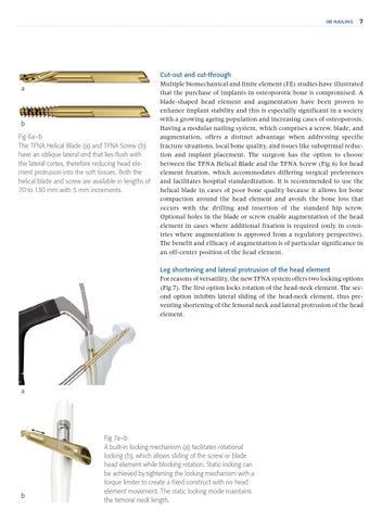
b Fig 6a–b The TFNA Helical Blade (a) and TFNA Screw (b) have an oblique lateral end that lies flush with the lateral cortex, therefore reducing head element protrusion into the soft tissues. Both the helical blade and screw are available in lengths of 70 to 130 mm with 5 mm increments.
7
Cut-out and cut-through Multiple biomechanical and finite element (FE) studies have illustrated that the purchase of implants in osteoporotic bone is compromised. A blade-shaped head element and augmentation have been proven to enhance implant stability and this is especially significant in a society with a growing ageing population and increasing cases of osteoporosis. Having a modular nailing system, which comprises a screw, blade, and augmentation, offers a distinct advantage when addressing specific fracture situations, local bone quality, and issues like suboptimal reduction and implant placement. The surgeon has the option to choose between the TFNA Helical Blade and the TFNA Screw (Fig 6) for head element fixation, which accommodates differing surgical preferences and facilitates hospital standardization. It is recommended to use the helical blade in cases of poor bone quality because it allows for bone compaction around the head element and avoids the bone loss that occurs with the drilling and insertion of the standard hip screw. Optional holes in the blade or screw enable augmentation of the head element in cases where additional fixation is required (only in countries where augmentation is approved from a regulatory perspective). The benefit and efficacy of augmentation is of particular significance in an off-center position of the head element. Leg shortening and lateral protrusion of the head element For reasons of versatility, the new TFNA system offers two locking options (Fig 7). The first option locks rotation of the head-neck element. The second option inhibits lateral sliding of the head-neck element, thus preventing shortening of the femoral neck and lateral protrusion of the head element.
a
b
Fig 7a–b A built-in locking mechanism (a) facilitates rotational locking (b), which allows sliding of the screw or blade head element while blocking rotation. Static locking can be achieved by tightening the locking mechanism with a torque limiter to create a fixed construct with no head element movement. The static locking mode maintains the femoral neck length.