AINISH SHETH
CONTENT 1. MEMORY - BUILT 05 2. SCAFFOLDED 2 5 3. ABACUS 35 4. URBAN ENCLAVE 4 9 5. APERTURE 5 9

4
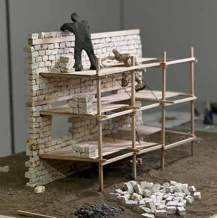
Loss is a universal experience. It can come in many forms, at any time, and has the potential to bring forth intense emotions. While it is often seen with a negative connotation, it has frequently proven to be a catalyst for positive growth and transformation.
The project aims to address this very idea of loss architecturally, through the concept of erosion. Erosion is one of the most natural phenomenons, which broadly results in the natural decomposition of the outermost layer, to reveal the beautiful and permanent inner layer.
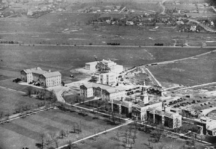
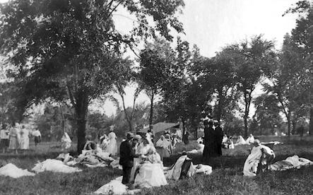
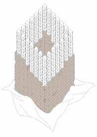
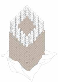
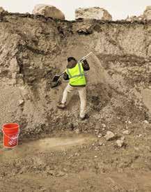
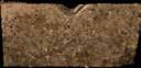
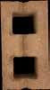
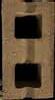
Loss is represented by clay blocks, the softer exterior material, and concrete, the harder interior material. The exterior gradually erodes to reveal a stronger, more permanent interior structure. It is sited on the University at Buffalo’s South campus, where the 2012 discovery of bodies, buried in shallow graves, estimated at over 3,000 individuals, provides an opportunity for acknowledgment. These bodies are the remains of men and women who died at the former Erie County Poorhouse, now UB’s Hayes Hall, and its related hospital.
Built in mid 19th century, the poorhouse institutionalized the poor, mentally and physically handicapped, and those seen as morally deficient by the society. Here they died, separated and estranged from their families and society. A century later, the cemetery had been long forgotten under the busy university campus.
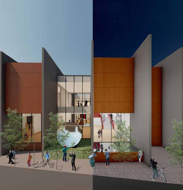
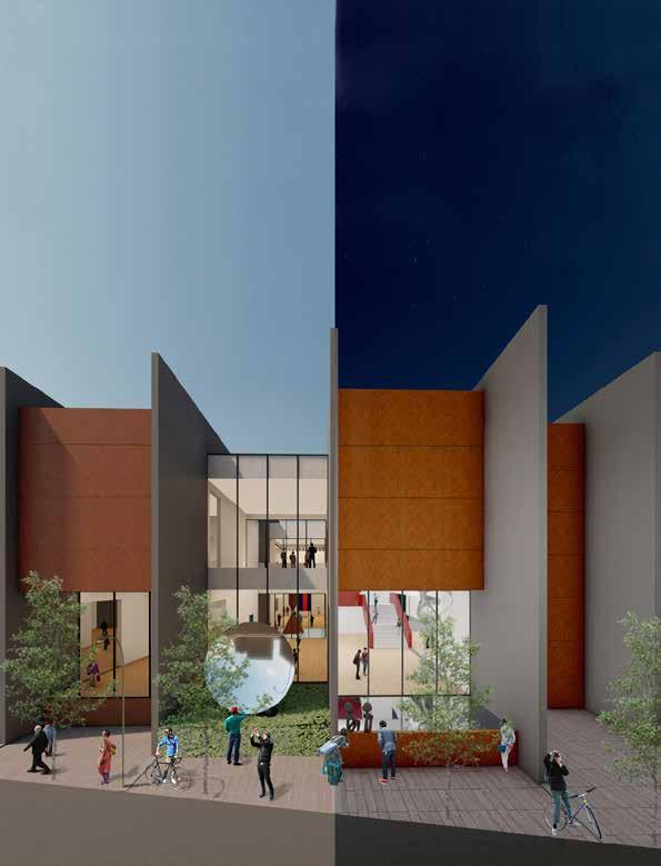
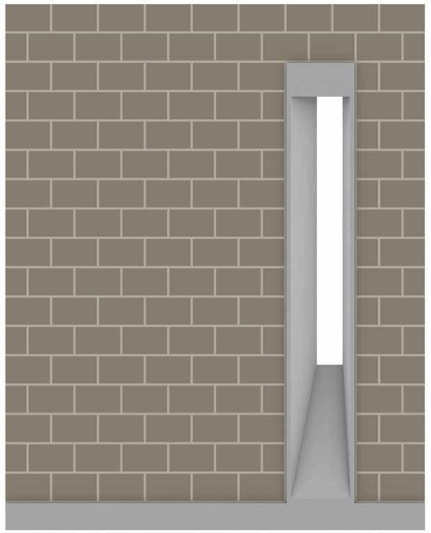
The proposed installation takes the form of a walled, square enclosure. It creates a visible presence on campus, while its interior space is set aside and reserved for these individuals, providing a level of dignity in death which was denied to them in life. Materializing the Loss acknowledges the deaths that occurred in this poorhouse, and by doing so, it means to pay its respects to the dead. It also attempts to address its own history that was built on the legacy of the situation at the Erie County Poorhouse, to further sensitize and strengthen the university and local communities will become stronger. Through the earth that builds up the memorial, and the earth that keeps the thousands buried, the erosion of loss reveals their stronger core.
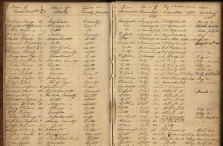
Far Top Left 1853 - Names of the estranged at the almshouse.
(Source: Buffalolib.org)
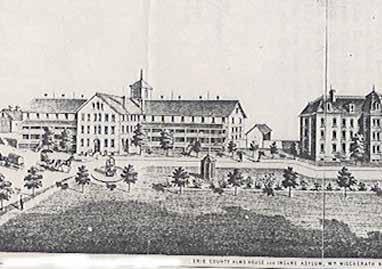
Far Middle Left and Far Bottom Left 1851 Rendering of the newly built Erie County Poorhouse and Insane Asylum. The building at right is currently known as Hayes Hall at the University at Buffalo. (Source: UB Archives)
Left
In 2012, during a road reconstruction project, shallow graves were discovered at the site of the poorhouse cemetery. The map shows the locations of bodies found, and estimated locations of up to 3,000 more still buried under the university campus.
(Source: Masters Thesis, Anthony, Alexis)
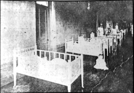
In the late 19th century, Almshouse residents would have lived in cramped quarters like this, estranged from their families and hidden from society.
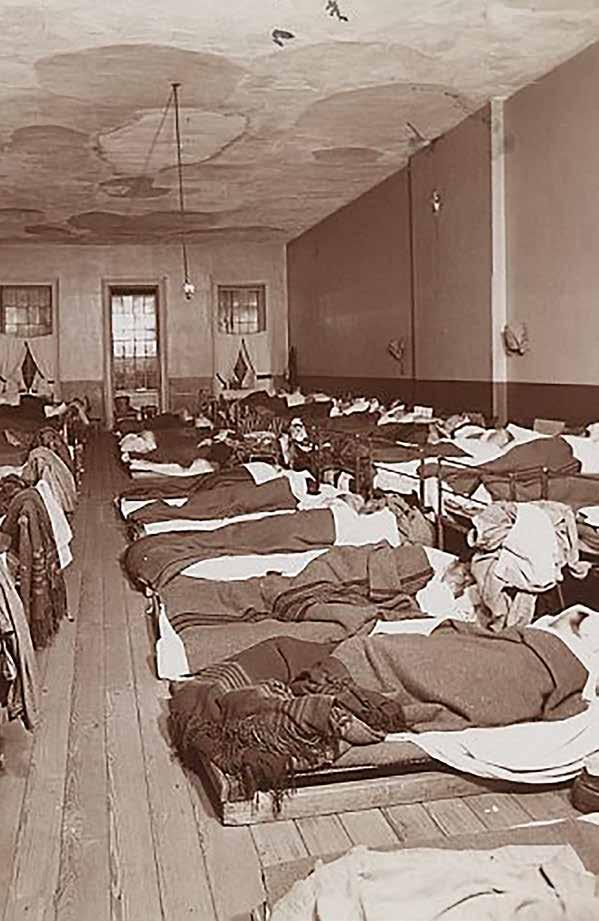
(Source: historycollection.com)
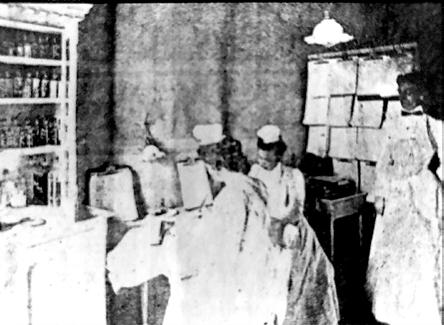
Far Middle Right 1990’s- Inside the Apothecary at the Erie County Almshouse
Far Bottom Right 1920’s - Inmates evacuated during a devastating fire leaving them homeless.
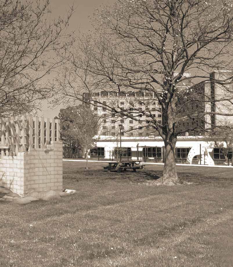
The final installation will be located on the UB South Campus, adjacent to Michael Road. The original cemetery location has been lost to time however, during a 2012 project remains were excavated around this location. Anthropologists and archaeologists at the University saved the remains, and relocated them into storage for study and eventual reinternment.
While the university has also created a memorial garden on South Campus, the location of this monument is far removed from the location of the existing graves, still forgotten under a parking lot and patch of grass next to the university’s daycare.
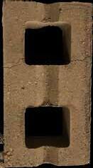
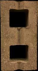
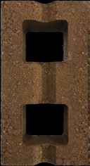
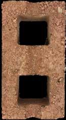
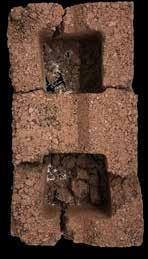
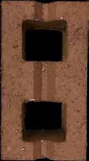
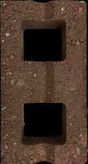
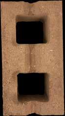
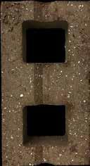
Based on this, our project aims to immortalize each of these individuals, and each brick represents each person who were treated like they were. The installation means to imply that even though their lives and the stories were lost in time, our installation is a modest attempt at allowing the dead to leave their mark on the city’s history and story. In the installation, the concrete that is poured into the cavity of each brick is representative of their memory, and what remains of them.
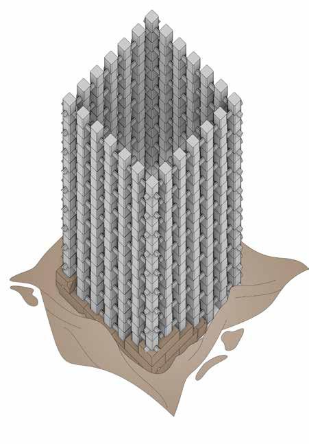
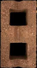
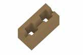
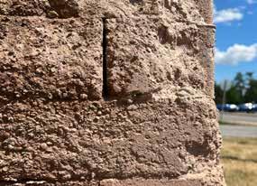
The concept of cavity brick for the installation emerged from an idea of having a sanctimonious enclosure as the core, that honored the dead. To further create just a visual access, a semi-permeable screen through columns was created all across its perimeter, which passed through these double cavity bricks.
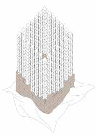
Next, the square was chosen as the shape mostly due to its symmetrical, equal and pure form. Visual aesthetics is one of the most important aspects for an installation, and a similar view from all the sides is an imperative thing for the artwork installation. The same thing was further reinforced with selecting English Bond as the style of masonry for the installation.
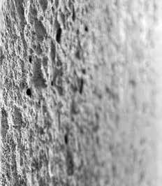
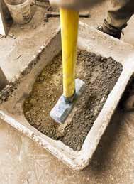
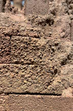
With erosion as one of the most symbolical parts of the installation, its outer layer has been made out of dirt clay, which is projected to gradually erode over the years to reveal a more complex and sanctimonious structure made out of concrete.
Finally, two alternating brick layers will form the outer brick structure, the mix for whom was intricately designed after 10+ iterations.
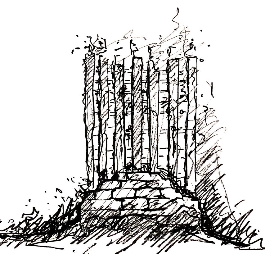
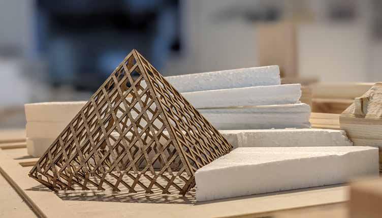
Top Far Left Sketches: Conceptual sketches of proposed installation
Bottom Far Left (Left to right): Conceptual models of erosion process
Left (Top and Bottom) Working drawings of the installation from two different levels
County Line Stone is a quarry located in Akron, NY that typically provides stones of different sizes to be used in different construction materials and applications.
Test 3:
Quarry Clay: 47% Sand: 29% Portland Cement: 14%
Test 2: Wet Clay: 57% Sand: 29% White Lime: 7% Black Lime: 7%
-Uneven distribution of material
-Low initial strength -Brittle
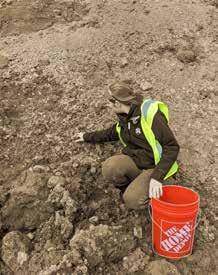
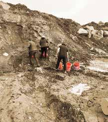
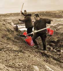
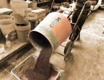
The project utilizes a large quantity of material with a variety of material types. To accurately assess the materials a sample was taken from various places visited on site, and a soil test was done. These tests show the raw material mixtures and allow a further understanding the different particle sizes and materials we were getting from the raw earth materials.
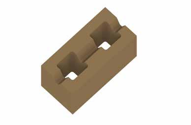
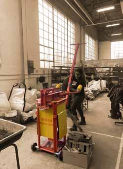
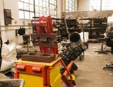
earlier explorations focused on qualities particular materials and mixtures of materials, ultimately determined to juxtapose soft and materials. To do this, we decided to use the compressed earth block press, which creates blocks whose voids could be used to combine or interlock with another material component.
While the earlier explorations focused on qualities and mixtures of materials, we ultimately determined to juxtapose soft and hard materials. To do this, we decided to use the compressed earth block press, which creates modular blocks whose voids could interlock with another material component.
material concept is to create an initial structure relatively soft, erosive block which will over time. Using this as a formwork, a more lasting, resilient internal structure indroduced in the form of concrete poured into vertical and horizontal network of cells and within the modular block wall. To achieve desired qualities, a precise mixture was devised block; one which was firm enough to be transported and stacked, but also weak enough to and erode to reveal the internal core.
explorations achieved numerous qualities, from the lightness and textural through introduction of perlite or and the rich color and relative strength of clay.
Test 6: Quarry Clay: 43% Wet Clay: 29% Sand: 14% Portland Cement: 14%
materials were used for the blocks. Soil, lime, were sourced from a local quarry. Since soil lacked sufficient clay content to strong blocks, a portion of refined clay was
-Low initial strength -Brittle
Test 7: Quarry Clay: 43% Wet Clay: 29% Charcoal: 14% Lime: 14%
Test 1: Wet Clay: 52% Sand: 26% Charcoal: 18% Portland Cement: 4%
-Low initial strength -Non-absorbant
-Non-absorbant -Brittle
The material concept is to create an initial structure from a relatively soft, erosive block which will degrade over time. Using this as a form work, a harder, more lasting, resilient internal structure is introduced in the form of concrete poured into the vertical and horizontal network of cells and grooves within the modular block wall. To achieve the desired qualities, a precise mixture was devised for the block; one which was firm enough to be transported and stacked, but also weak enough to deteriorate and erode to reveal the internal core.
The initial explorations achieved numerous desirable qualities, from the lightness and textural properties through introduction of perlite or charcoal, and the rich color and relative strength of refined clay.
Local materials were used for the blocks. Soil, lime, and sand were sourced from a local quarry. Since the quarry soil lacked sufficient clay content to produce strong blocks, a portion of refined clay was added.
Test 4:
Test 10: Quarry Clay: 29%
Wet Clay: 36% Sand: 21% Lime: 14%
-Low initial strength -Uneven distribution
the Aurum 3000 Earth Block Press to produce blocks with voids which allow us to pour a concrete network of block cells to create a rigid, unified, structure. Specifications: Hollow 290 size (L x W x H, in mm) 290 x
Test 11: Quarry Clay: 67% White Lime: 13% Sand: 13% Perlite: 7%
Test 5: Quarry Clay: 43% Wet Clay: 29% Sand: 14% Lime: 14%
-Expensive -Low initial strength
Final Mix: Quarry Clay: 43% Refined Clay Dust: 29% Sand: 21% Agricultural Lime: 7%
Test 6: Quarry Clay: 43% Wet Clay: 29% Sand: 14% Portland Cement: 14%
-Low initial strength -Low initial strength -Brittle
-Too much clay -High initial strength -Erodes in 3 months
Test 7: Quarry Clay: 43%
Wet Clay: 29% Charcoal: 14% Lime: 14%
-Brittle -Low initial strength -Non-absorbant
-Unknown material -Uneven distribution -Low initial strength -Too much clay
Test 8: Wet Clay: Sand: Portland Cement:


 Guided by Instructors : Christopher Romano, Dr. Kimberly C. Meehan Partner - Jessica Rote
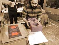
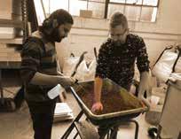
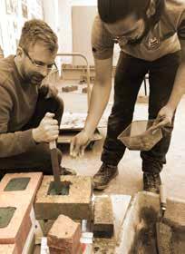
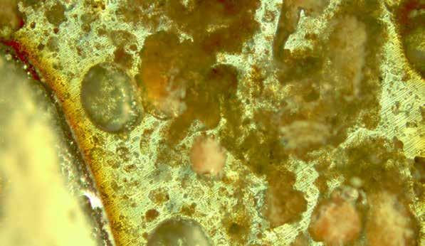
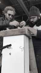
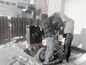
As part of the Intellectual Domain Seminar, in the spring ‘22 semester, I worked with Jessica Rote under the guidance of faculty members Christopher Romano and Dr Kimberly Meehan on testing various cementitious materials like Fly Ash, Silica Fume, Slag and Iron Ore. We mixed these materials each at a time with compressed earth blocks(CEB), and put them through compression testing, water testing. We also studied them under reflected light microscopic imageries.
Going into the nuances, we selected 6 different CEB blocks with distinct mixtures and eventually concluded that the one with agricultural lime as the additive proved to be the most desirable block for our project. We made the choice after a number of considerations such as all natural and materials, handling convenience and rate of erosion.
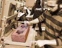
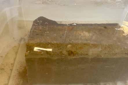
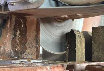
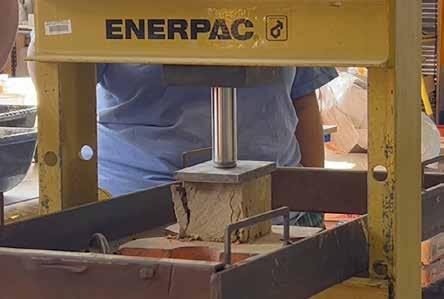
Far Left Images (Top to Bottom): Curring Blocks with Tile cutter and Testing with series of compression and water tests to understand strength and erosion under various condition.
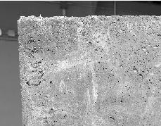
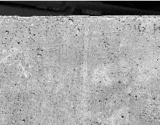
Left: Reflected light microscopic images of final bricks to understand cementation and bonding process at macro level
Bottom: Microscopic images of final bricks to understand material composition and proportions.
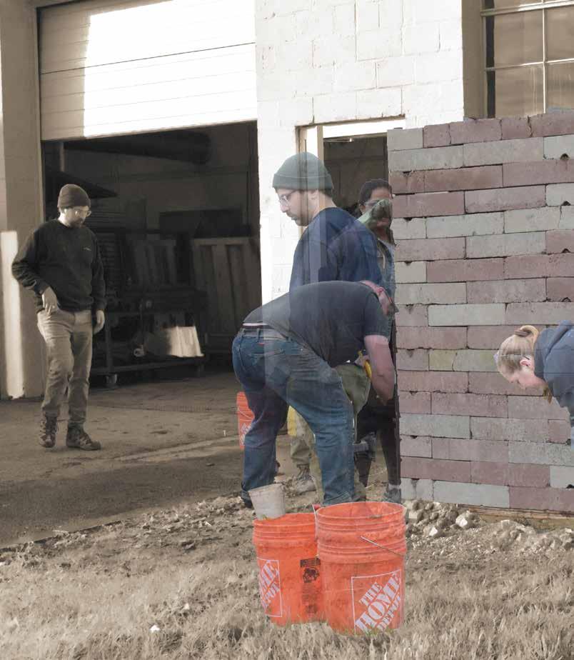
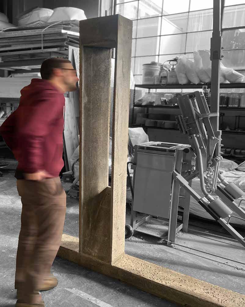
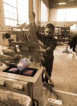
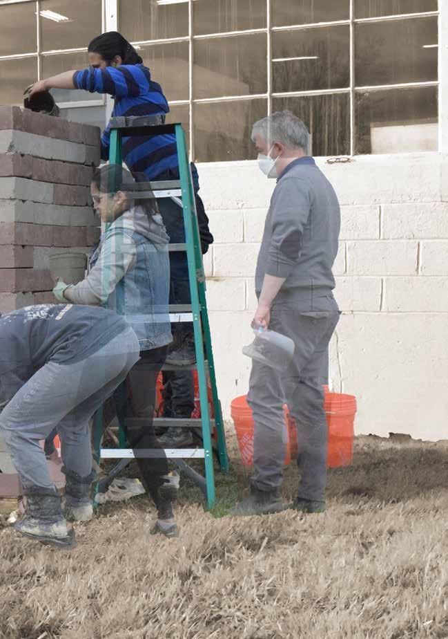
Acknowledgment: Digital collage of the assembly process including every person and every tool who/which helped in process
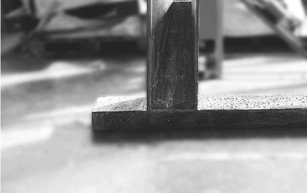
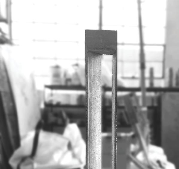
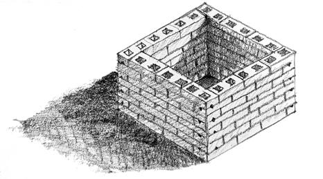
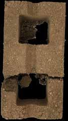
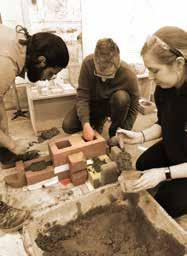
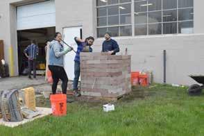
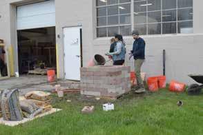
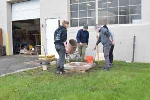
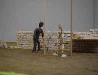
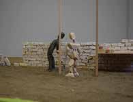
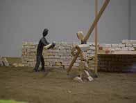
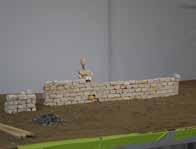
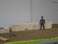
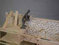
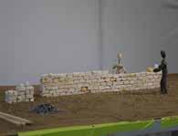
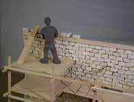
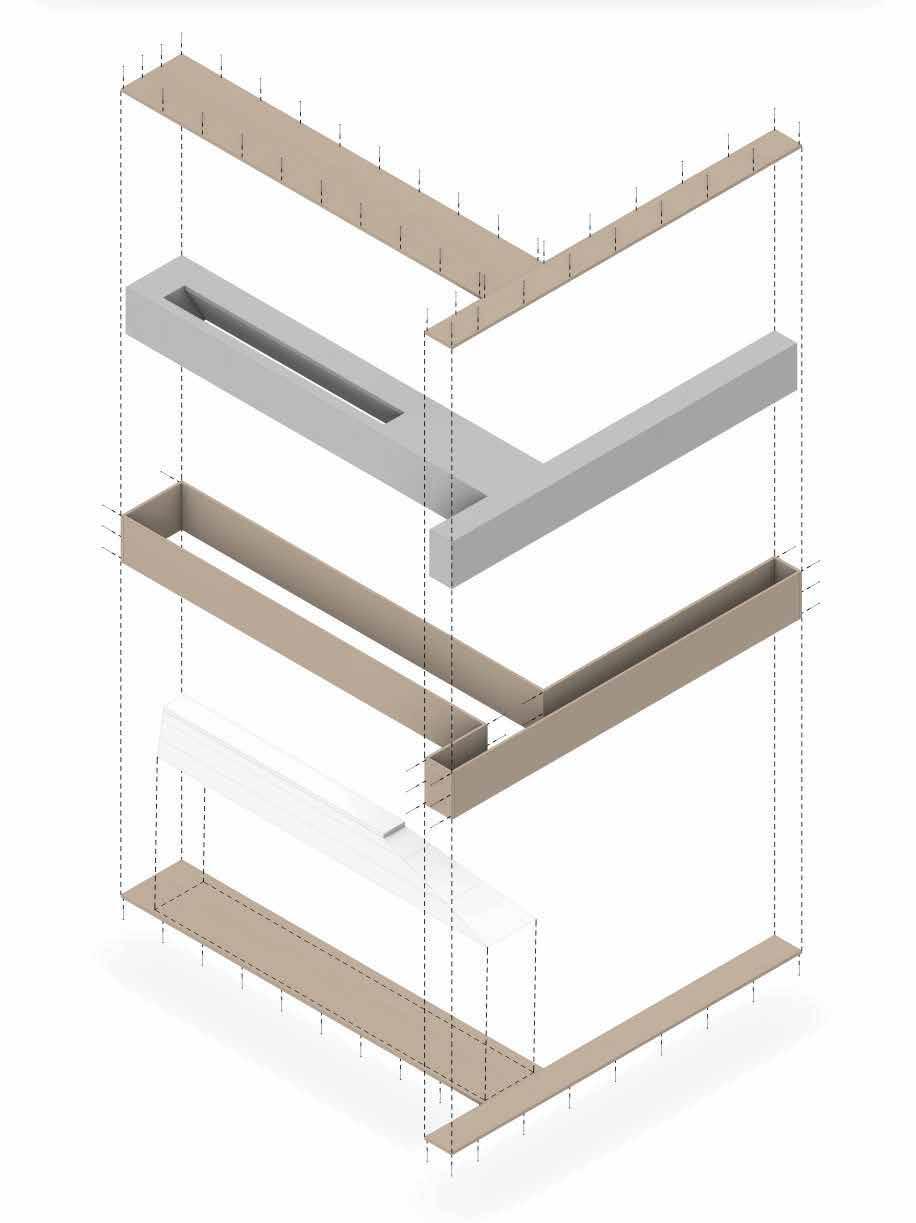
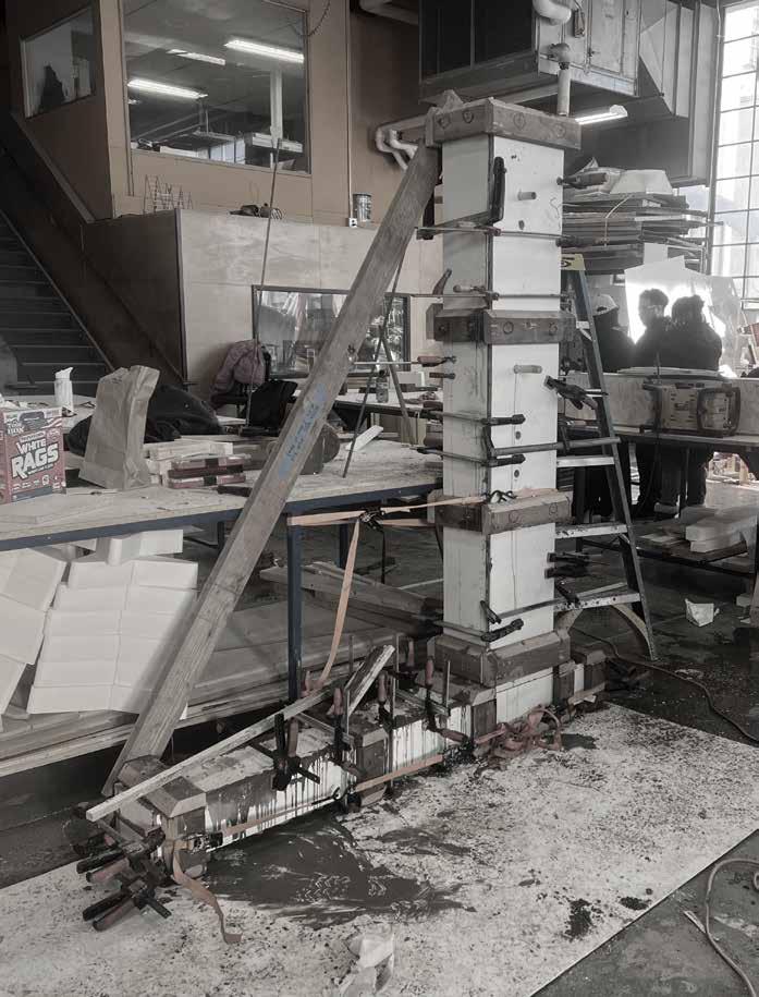
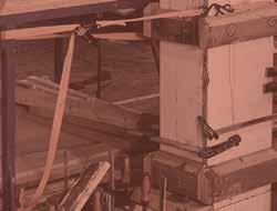
The final assembly is comprised of individual drystacked compressed earth blocks forming solid walls. The use of these blocks allow for ease of transport, and assembly. The walls take the shape of a closed square, creating an inaccessible void which is reserved for the memory of those buried in the surrounding ground.
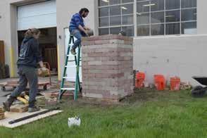
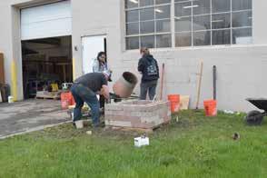
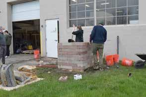
The dry-stacked walls themselves are used as formwork into which concrete is poured. The hardened concrete creates a more rigid, lasting interior structural network which is designed to remain, even after the earthen blocks have eroded away. To ensure structural stability, vertical rebar is centered in each cell as the concrete is poured. The form of the block features a notch into which we will lay horizontal rebar tying the structure together.
Right: Series of 6 images showing assembly process
1 Place blocks in square formation allowing rebar in each cell.
assembly is comprised of individual drycompressed earth blocks forming solid these blocks allow for ease of assembly. The walls take the shape square, creating an inaccessible void reserved for the memory of those buried in ground.
final assembly is comprised of individual drystacked compressed earth blocks forming solid The use of these blocks allow for ease of transport, and assembly. The walls take the shape closed square, creating an inaccessible void is reserved for the memory of those buried in surrounding ground.
walls themselves are used as which concrete is poured. The concrete creates a more rigid, lasting network which is designed to after the earthen blocks have eroded structural stability, vertical rebar is cell as the concrete is poured. The features a notch into which we will rebar tying the structure together.
dry-stacked walls themselves are used as formwork into which concrete is poured. The hardened concrete creates a more rigid, lasting interior structural network which is designed to remain, even after the earthen blocks have eroded To ensure structural stability, vertical rebar is centered in each cell as the concrete is poured. The of the block features a notch into which we will horizontal rebar tying the structure together.
Diagrams: Series of 6 diagrams showing proposed assembly process
1 Place blocks in square formation allowing for vertical rebar in each cell.
1 Place blocks in square formation allowing for vertical rebar in each cell.
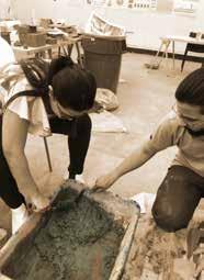
2 Concrete is poured into existing cells as the wall is gradually built up.
2 Concrete is poured into existing cells as the wall is gradually built up.
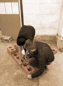
3 Horizontal reinforcement laid in grooves in blocks and concrete poured around.
The final assembly is comprised of individual drystacked compressed earth blocks forming solid walls. The use of these blocks allow for ease of transport, and assembly. The walls take the shape of a closed square, creating an inaccessible void which is reserved for the memory of those buried in the surrounding ground.
The final assembly is comprised of individual drystacked compressed earth blocks forming solid walls. The use of these blocks allow for ease of transport, and assembly. The walls take the shape of a closed square, creating an inaccessible void which is reserved for the memory of those buried in the surrounding ground.
The dry-stacked walls themselves are used as formwork into which concrete is poured. The hardened concrete creates a more rigid, lasting interior structural network which is designed to remain, even after the earthen blocks have eroded away. To ensure structural stability, vertical rebar is centered in each cell as the concrete is poured. The form of the block features a notch into which we will lay horizontal rebar tying the structure together.
The dry-stacked walls themselves are used as formwork into which concrete is poured. The hardened concrete creates a more rigid, lasting interior structural network which is designed to remain, even after the earthen blocks have eroded away. To ensure structural stability, vertical rebar is centered in each cell as the concrete is poured. The form of the block features a notch into which we will lay horizontal rebar tying the structure together.
The final assembly is comprised of individual dry-stacked compressed earth blocks forming solid walls. The use of these blocks allow for ease of transport, and assembly. The walls take the shape of a closed square, creating an inaccessible void which is reserved for the memory of those buried in the surrounding ground.
The dry-stacked walls themselves are used as form work into which concrete is poured. The hardened concrete creates a more rigid, lasting interior structural network which is designed to remain, even after the earthen blocks have eroded away. To ensure structural stability, vertical re-bar is centered in each cell as the concrete is poured. The form of the block features a notch into which we will lay horizontal re-bar tying the structure together.
2
REMEMBERED for vertical 2 Concrete is poured into existing cells as the wall is gradually built up.
2 Concrete is poured into existing cells as the wall is gradually built up. prefabricated
3
4
4
Build higher row by row, pouring concrete with every two block courses
prefabricated 4 Build higher row by row, pouring concrete with every two block courses
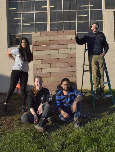
6 Finished structure
5 Final blocks put in place and concrete poured.
5 Final blocks put in place and concrete poured. 6 Finished structure
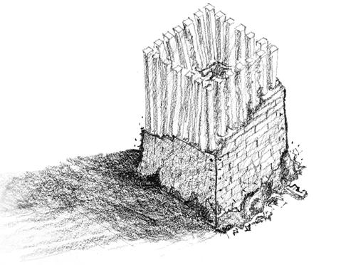
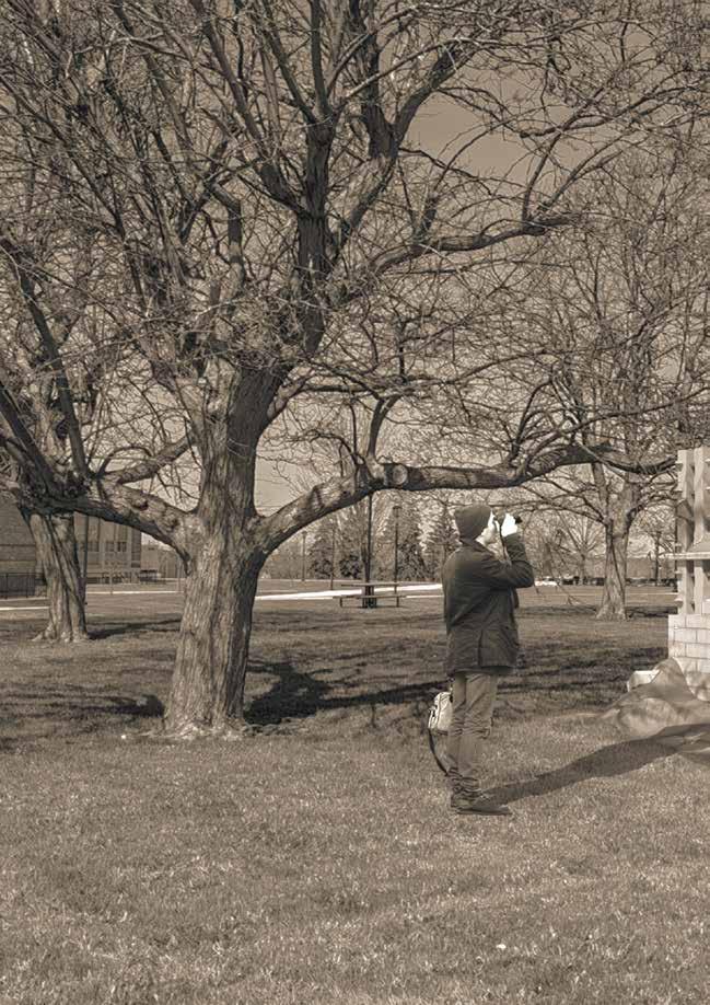
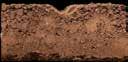
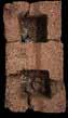
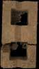
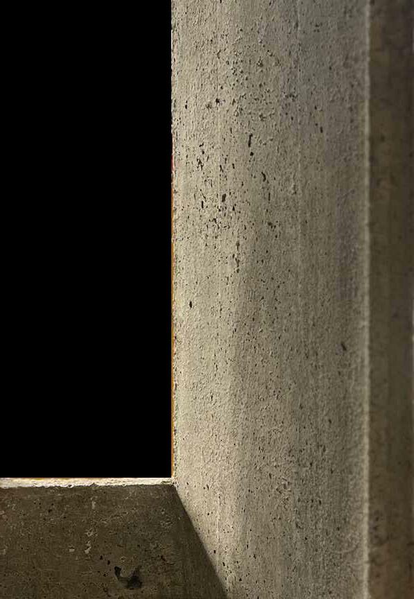
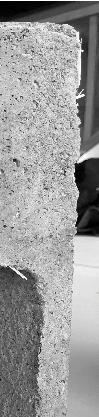
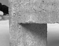
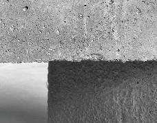
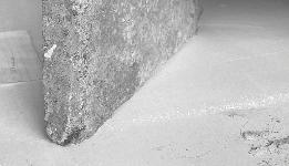
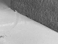
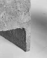
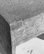
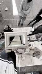
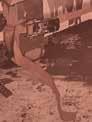
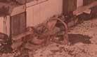
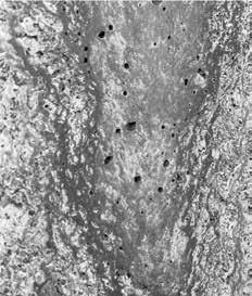
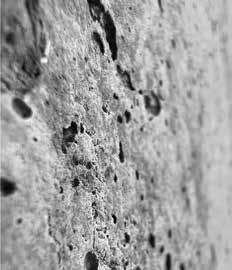
After the installation was completed, it was the erosion process that attracted a lot of attention. It all began with the corners as the erosion started from those points first. By the end of the second month we could observe a few holes between the columns from the top down, which had traveled the whole height of the column by the 6th month. We could finally observe the inaccessible enclosure that we had been envisioning since the beginning.
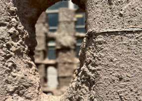
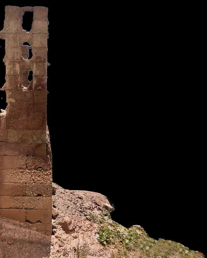
Left Condition of the installation after 6 months of erosion
Far Left Photograph of a section of installation after 2 months of erosion
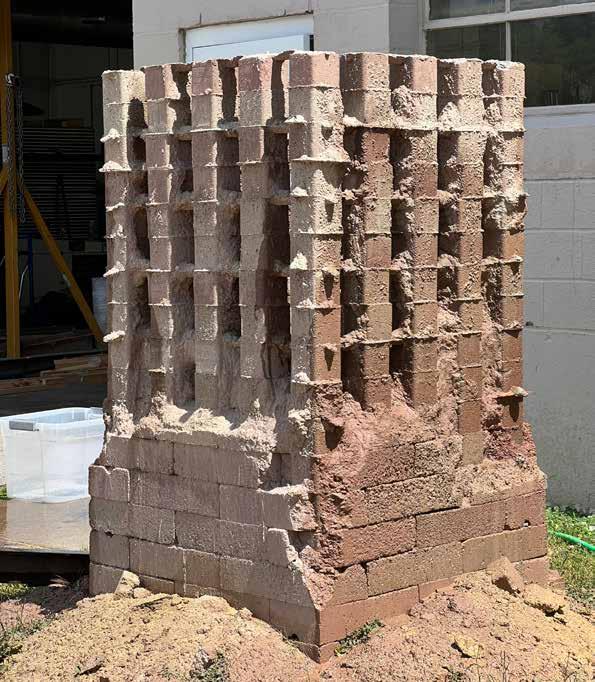
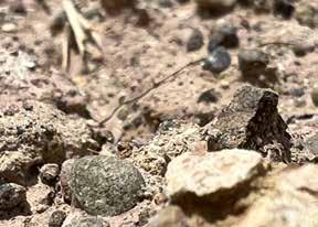
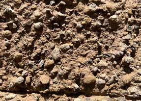
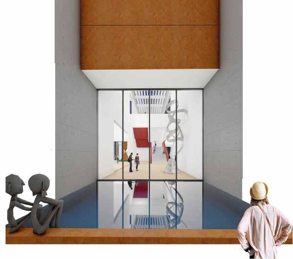
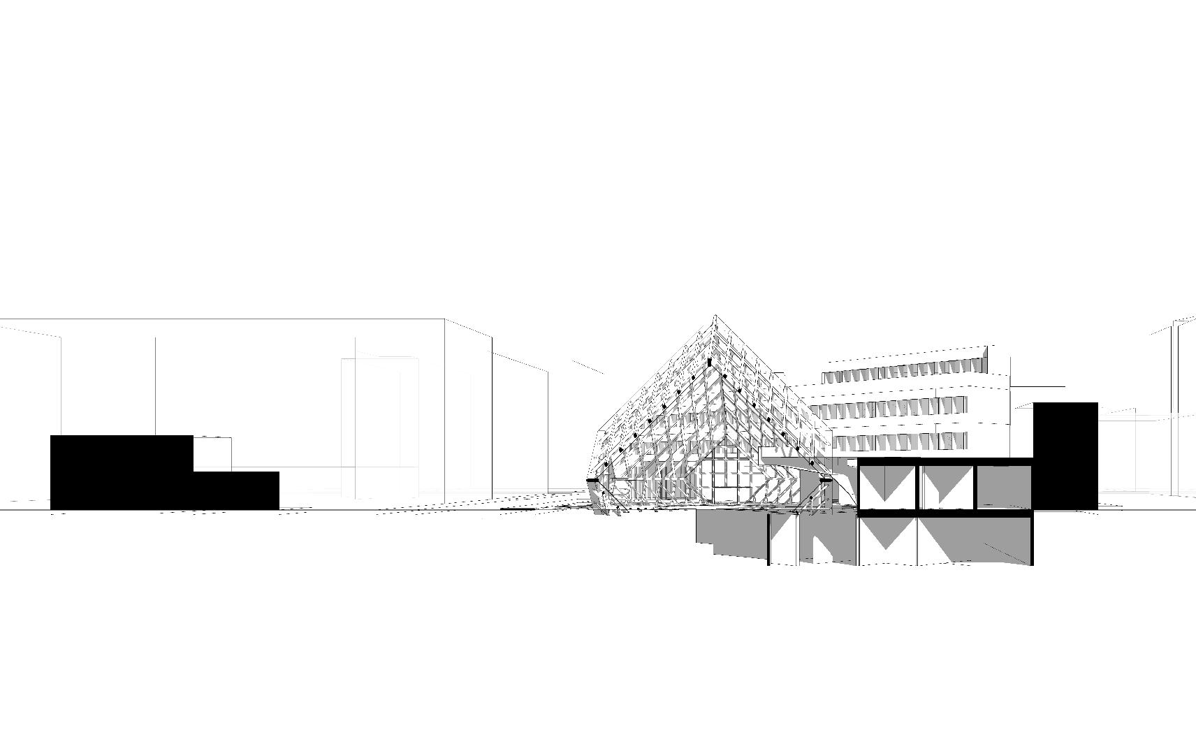
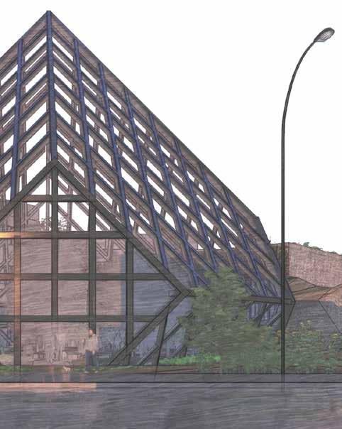
Image: Hybrid render over a model photograph showing the entrance space of pavilion
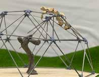
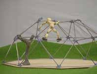
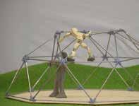
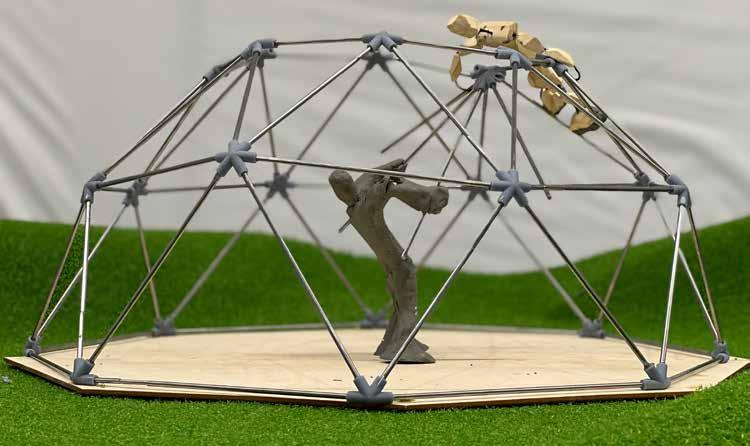
This project was undertaken as a precedent study to understand the differences in various systems of scaffolding. From learning about the foundations of such temporary structures, to studying the nuances of the material of construction, the amount of knowledge which was gained through this was immense.
I worked with another person for this study, and explored conventional bricklayers scaffolding made out of timber, and a geodesic dome as an anti-scaffolding system. Broadly speaking, we deduced that the bricklayers scaffolding was rendered a little useless when it came to erecting a wall that went in any other direction, than horizontal or vertical. Even for its contemporary, geometry seems to be a limiting factor after a particular point, as its rigid form prevents it from having much larger/wider application.
Top: Two people making geodesic dome with pre - fabricated elements.
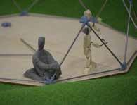
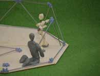
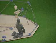
Right layer 1 (Left to Right): Two people assembling triangular geometries on site with pre fabricated materials
Right layer 2(Left to right):
Two people transforming the triangular segments to its place and attaching them on its desired location
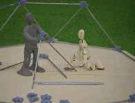
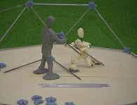
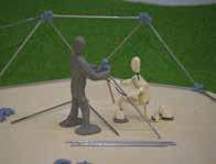
Right layer 3 (Left to Right):
One person lifting the triangular segments and passing them to the other person on the upper level of structure. The second person lifting it to its desired location and both of them attaching the segments together
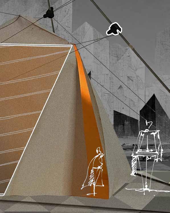
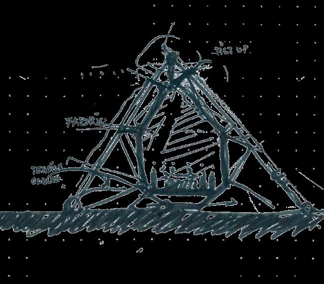
Above: Conceptual sketch of proposed pavilion
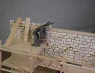
Far Right(Top to Bottom): Scaled Model photos showing assembly process
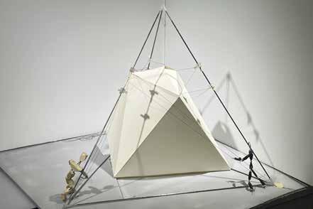
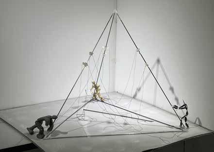
Tasked with creating a Pop Up Pavilion out of scaffolding materials, the precedent study helped in understanding the importance of temporary structures and the impact they have on the final building in the longer run.
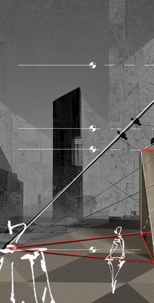
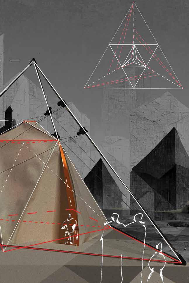
This pavilion was conceptualized on the idea of adding permanence to these temporary structures, for which the technique of inverting the endo and exo-skeletons of a geodesic structure was integrated. The idea also draws a very strong inspiration from the natural phenomenon of metamorphosis, wherein the larva constructing its own cocoon to hibernate and eventually evolve into a better self, forms the central idea of having a layered structure.
Next, a tetrahedron was finalized as the form of the exoskeleton of the pavilion, from which the fiberglass fabric would be suspended as the endo-skeleton of the structure.
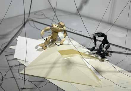
Another thing that the precedent study brought into the light was the simplicity of the triangles which formed the basic shape for the fiberglass endo-skeleton. It was an intersection of 13 different triangles across all three dimensions, with one triangle acting as a narrow opening to the pavilion.
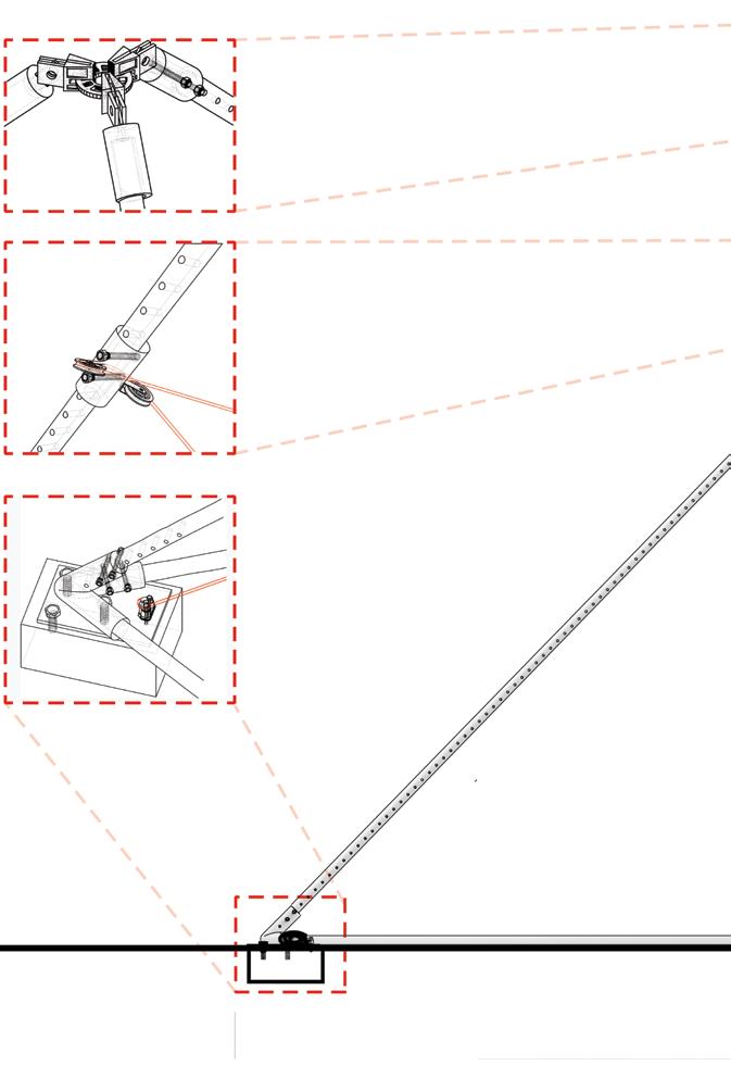
The images on the right detail-out the construction process of erecting the tetrahedron-shaped pop-up pavilion. The construction follows the rules of interlocking geometries in an equilateral pyramid, whose edges have been transformed into lightweight hollow metal pipes. Furthermore, there are cables that uphold the prefabricated fiberglass fabric through tensile forces. Finally, there is an assembly of pulleys and tensile cables that are bolted to the aforementioned lightweight hollow metal pipes.
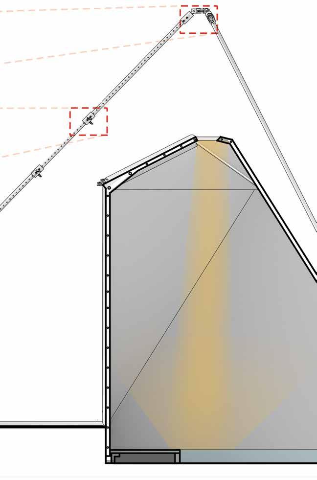
This visualization is to depict how the pavilion will act as an individual element with its own architectural character in the given context. Furthermore, a water body has been added inside the enclosure to primarily provide a sense of calmness and to act as a reflective element for the natural light that enters the pavilion right from the top.

 Instructors : Annette LeCuyer, Abigail Peters Partner - Mumuksha Patel
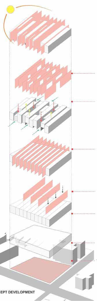
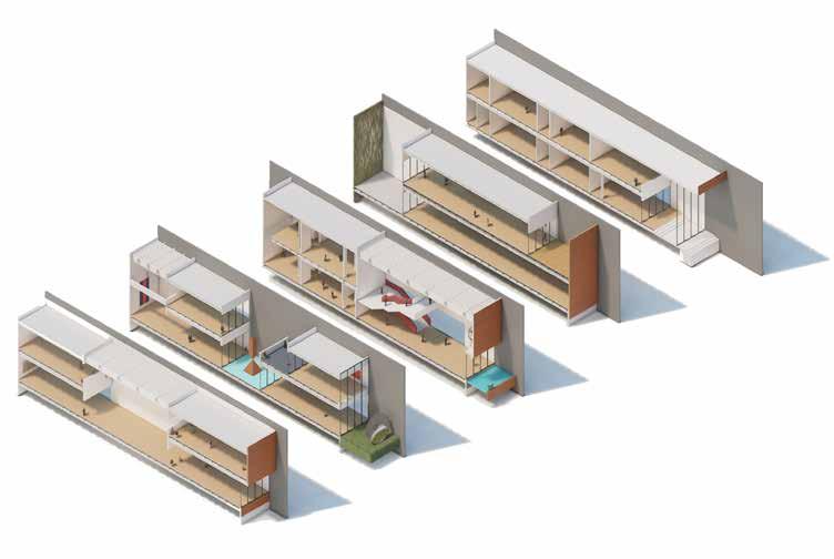
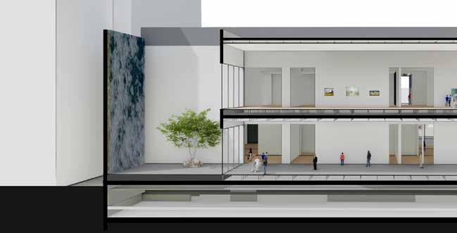
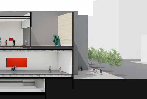
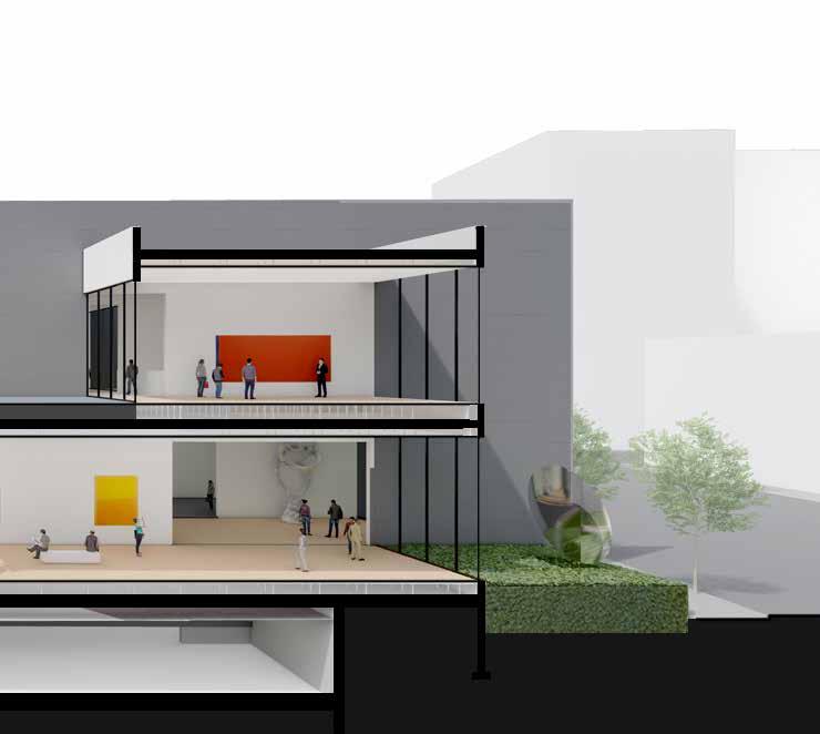
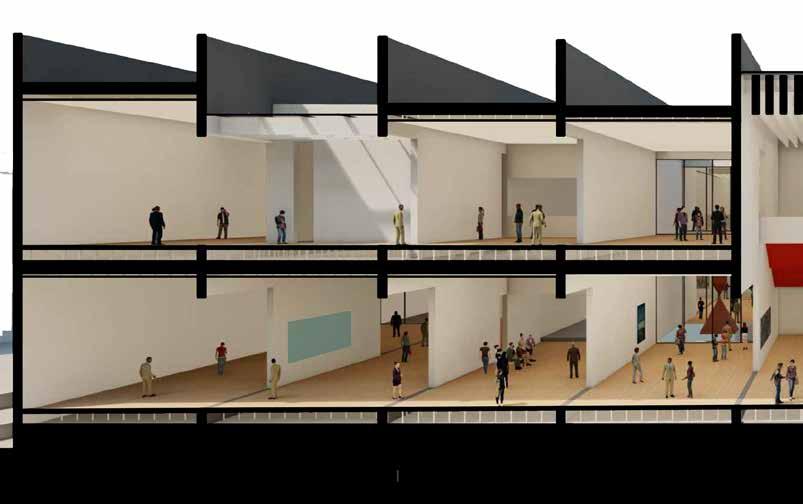
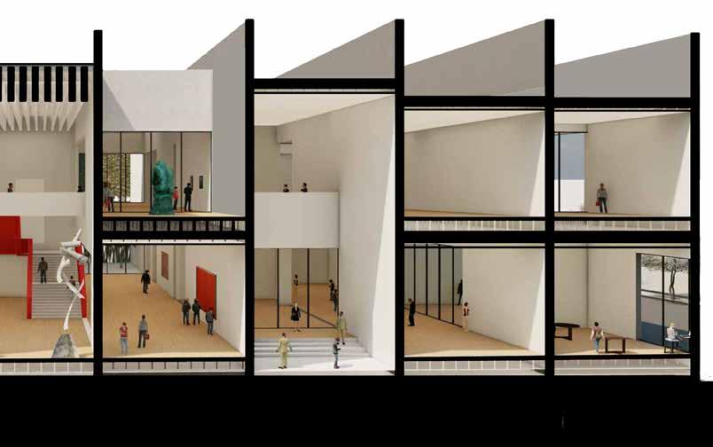
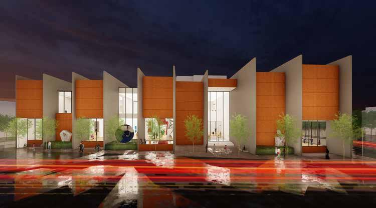
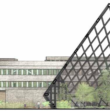
Abacus, meaning an oblong row of wires or grooves, forms the very fabric of this art museum. Conceptualized around nine such rows, it is made to encapsulate a wide variety of art galleries, especially for contemporary art. Segregated among two floors, it is strategically planned to empower artistry through facilities like classroom learning and digital teaching.
Located on the intersection of North Street and Delaware Avenue, the site posed a strong set of constraints, right from the word go. The site had a maximum contour height of 7 feet along its northern edge, which influenced the decision of entrances and exits. The adjoining residential building along its western edge also dictated the design to a certain extent, as it was imperative to address its privacy through the design.
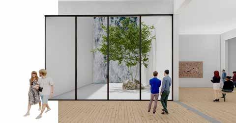
As the segmentation was being done through walls, the idea of staggering the spaces to create interesting voids further enhanced the design. On the exterior, this made way for perceptible pocket spaces, capable of hosting a wide array of artistry. Apart from that, spaces like terraces and courtyards introduced the aspect of internal voids to the design.
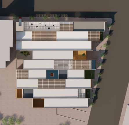
Where the courtyards and terraces brought an appropriate quanta of indirect and diffused light into the building, aesthetic strategies like water-bodies, translucent glass ceilings and double height spaces further elevated the design.
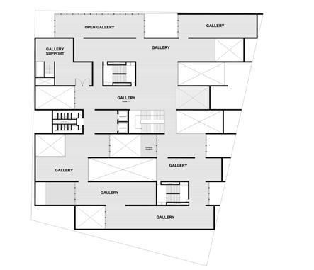
Top Far Left: View from the top showing the staggered planning
Bottom Far Left: Exploded view of the 5 intermediate adjoining segments
Left: The double height gallery, grid 6.
Above: Visualization of the courtyard and the gallery on the upper level
Middle: Visualization of the courtyard and the gallery on the upper level
Top Right: Gallery on ground level
Bottom: Perspective section from grid 4 showing two different voids and their connection with gallery spaces on different levels
When it comes to the internal voids, they can be classified broadly into courtyards, terraces, glass coverings and double height spaces. Courtyards have been strategically placed throughout the staggered blocks to increase the luminosity within the building. The courtyards are developed in a variety of ways to host art installations and sculptures, while providing a visual shift to the crowds ‘outside’ the building.
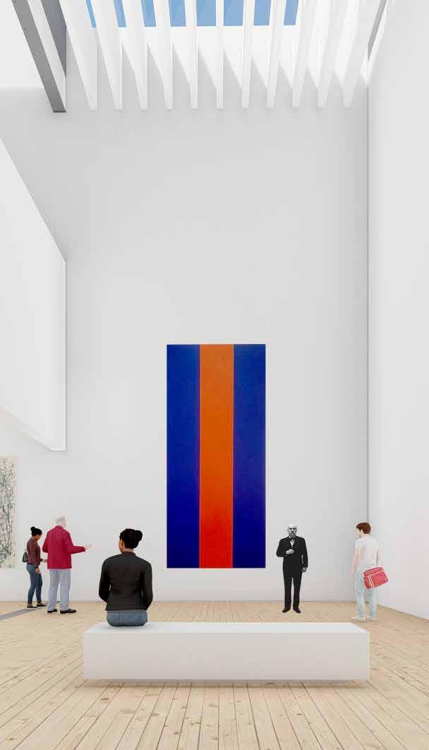
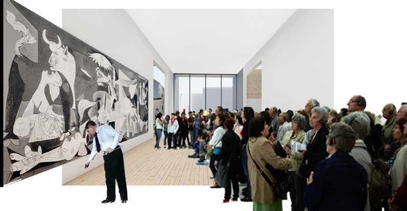
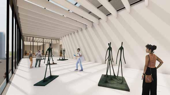
Double height spaces have been specifically planned to highlight large scale artworks in the museum, the experience of grandeur for which has been achieved through volumetric modulations within the building. Not only do they act as light shafts for the building, but they also play an important role in diversifying the user experience as one traverses through the widths and lengths of the building.
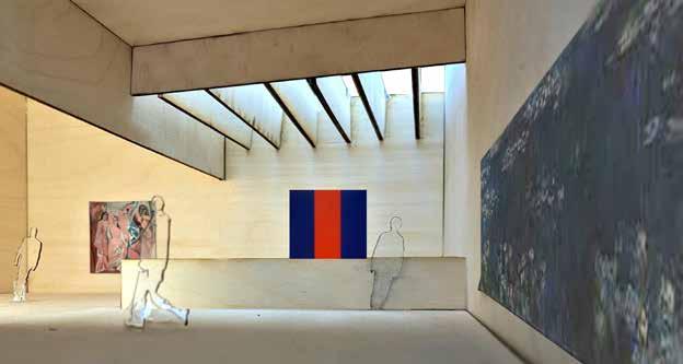
To further accentuate the use of light, the ceiling details have been drawn from the aforementioned Beyeler Foundation whose incorporation of glass to diffuse the ceiling light elevates the overall experience.
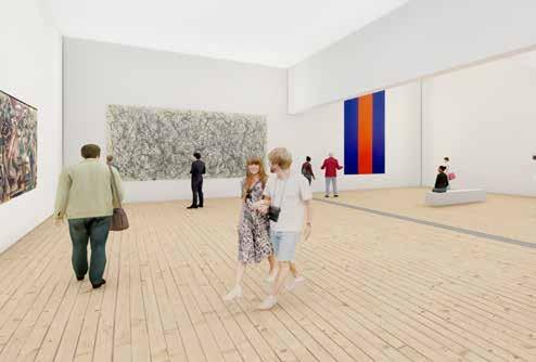
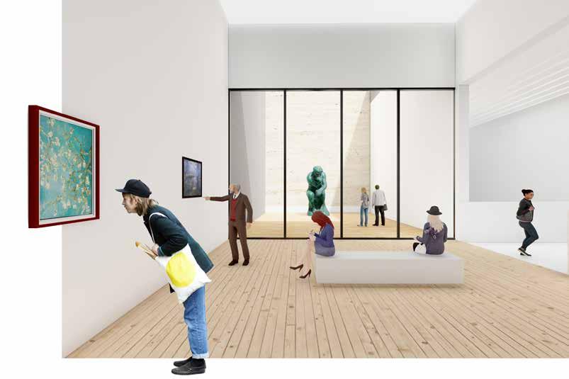
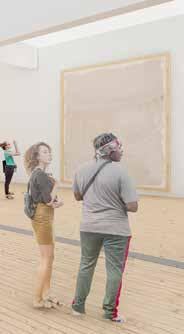
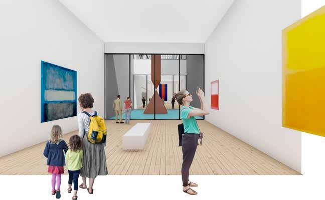
The building houses a variety of art galleries to deliver a diversity in experiences to the visitors. From galleries that overlook double height spaces, to the galleries that extend out towards a courtyard, the building ascertains to do justice to the artworks displayed in their premises.
A special emphasis on the ‘sculpture gallery’ has been paid, as it is one of the few spaces in the building that welcomes the southern light in its purest form. A number of sculptures placed strategically would further assist in dictating the path of traversing for the visitors.
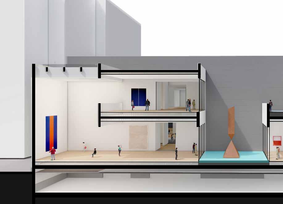
Left: Perspective section from grid 6 showing two different voids and their connections with gallery spaces on both levels
Bottom left: Visualization of the courtyard space and gallery area on lower level of grid 6 and 7
Bottom right: Visualization of the courtyard and gallery on lower level of grid 6
Left: Visualization of the ‘Sculpture Gallery’ on upper level of grid 1.
Far Left: Light - study model phonograph of the grid 3
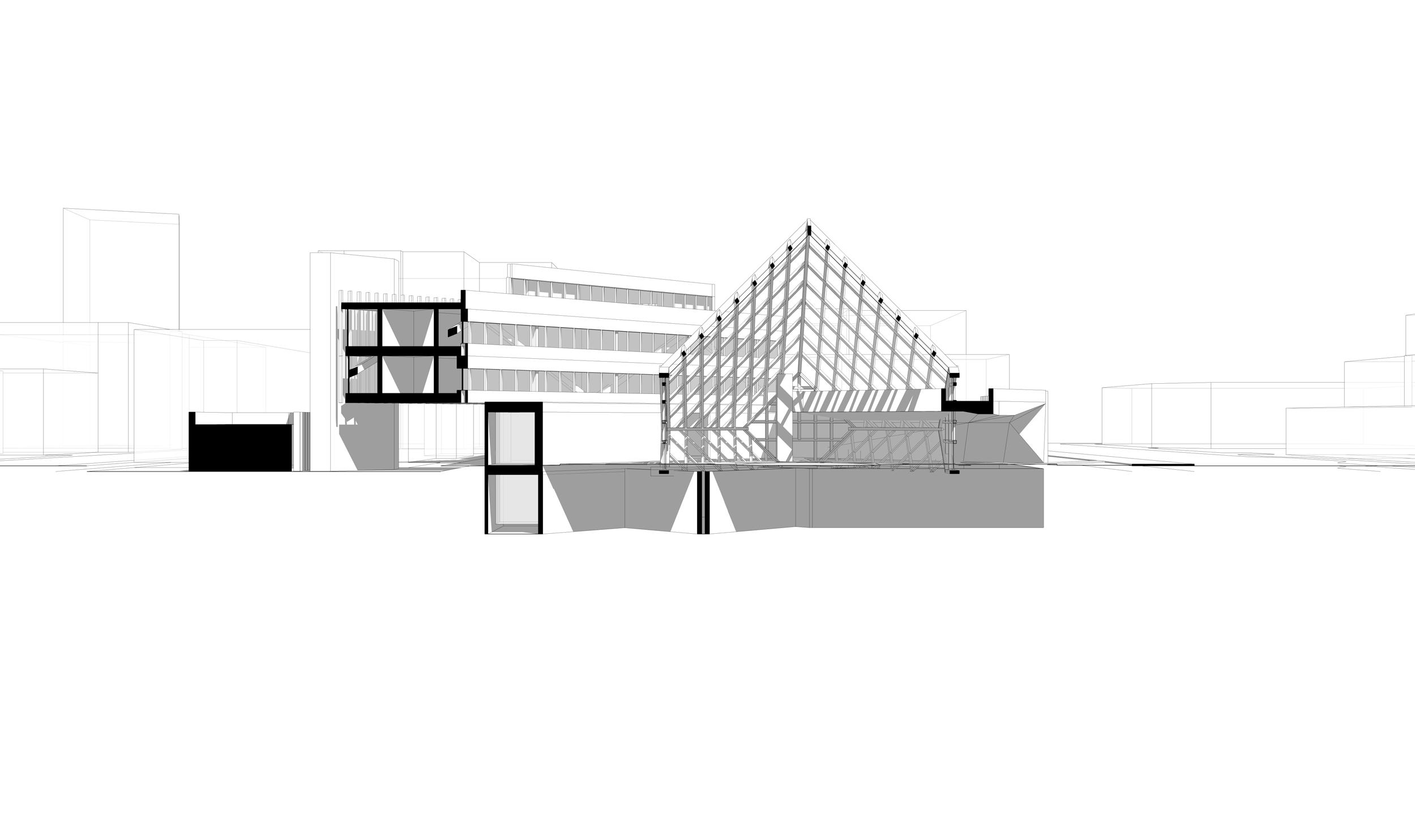
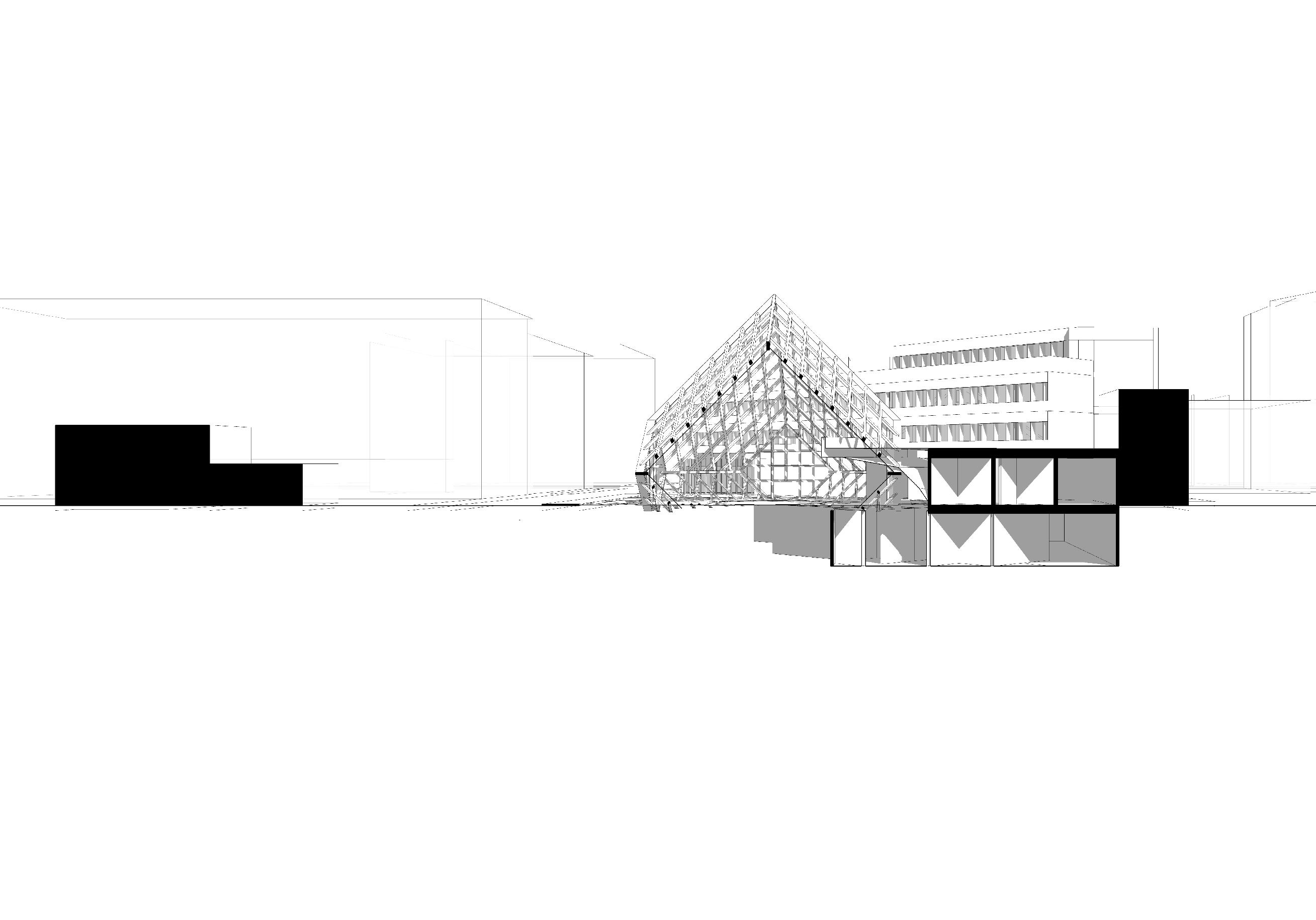
Bottom: North to South cross section of the building, focusing on vertical circulation looking West.

Right:
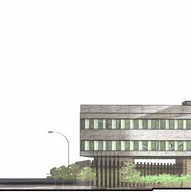
Bottom: Side elevation of the building from North Street
Fourth level - Special education classroom - Teachers workroom - Nurce office - SST office
Third level - Special education classroom - Art classroom - Locker spaces
Second level - Classrooms - Teachers resourceroom - Main office - Guidence suit - Office for principal and assistant principal
Ground Level - Greenhouse - School entry - Library - Computer Classroom - Banquet - Banquet kitchen and store - Loading unloading Deck
LANDSCAPE
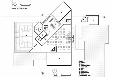
Basement - Gym - Locker rooms - Changing room - Kitchen - Bakery - School cafe
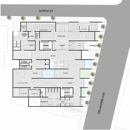
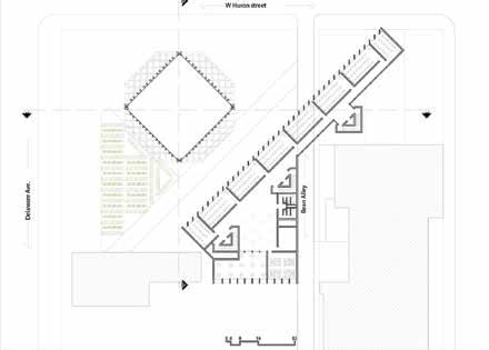
The building was planned as a definite response to the core downtown area in the city of Buffalo. Given its rich architectural history, its planning has always complemented the long term vision moving forward. There are number of community buildings like City hall, Court house etc. But there is certain absence of urban community spaces that would be addressed through this design.
Among everything else, one aspect that stands out particularly is an enclosure that envelopes the entire public realm. It is a public node that invites the people within its boundaries, and offers them with a variety of experiences. From secluded seating to covered pathways, the entire space is designed meticulously to provide a diversity every time one visits the place.
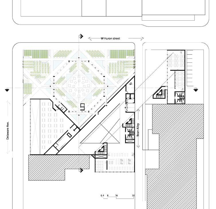
Juxtaposition is one of the key aspects that has been employed in the design process for this building. It is specifically evident in three separate areas, namely planning, form and materials.
From addressing the linear grid that has built the town, to introducing the tangential grid that stands out in the entire urban fabric; the juxtaposition of two distinct grids opens up an entirely new avenue for further massing and design development.
The forms of the buildings have been heavily inspired from the rich architectural history of the town, that proudly incorporates Modernist, Brutalist and Art Deco styles of architecture. While the urban enclosure is a representation of the very modernist style of architecture, the school building starkly contrasts as a Brutalist building in the same complex.
Apart from that, planning is another key element that has dictated a number of decisions throughout the design process. From opening up more than half of the entire front, to placing the school building at the very back of the site , the amalgamation of two distinct grids with the necessity of an open urban space has influenced the most spectacular design decision of letting the building cross over the road to another part of the site.


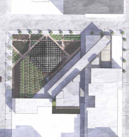
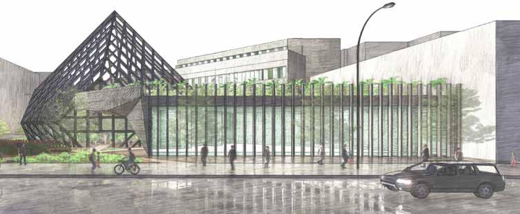
The most interesting aspect of the entire complex is the urban enclosure, that peculiarly houses a variety of organic farms. The public finds its attraction in an octahedron-shaped metal and glass enclosure, with access on all four sides for the public. The entire space is decked with wooden planks, and its punctuated with secluded as well as diner seating, to further enhance the earthly experience for the users.

Top: Section through public greenhouse and banquet hall


Volumetric proportions in the entire complex are something that have been carved out after a very careful contextual study. With areas below the ground level connecting seamlessly with their counterparts above, the user is certain experience a wide range of spaces throughout the complex.


Above Section through the classroom, greenhouse and Banquet.
Top Rendered View of entrance of the greenhouse
Instructors : Christopher Romano, Michael Hoover, Randy Fernando Team - : Luke Dole, Jackson Gaylord, Joshua Kneer, Patrick Ma, John Mark Silbert Nachbar, Harsh Thakkar
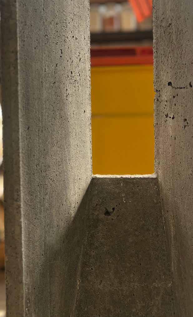
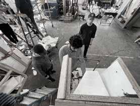
As part of the Structures - 3 course in the Fall 2022 semester, a pre-cast aperture/opening was to be made in a wall, out of concrete. Working in a group of 7 people, the whole project was executed with a lot of precision.
From volumes and quantities to the chamfer angles and concrete mixes, the technical details were the most important precedents that were calculated for the project.
The form work for the same was prepared out of 3/4” thick plywood, and a concrete mix of 1:2:2:1 (Portland cement, concrete sand, washed screenings, 1A stone) were utilized.


Finally, a frame of re-bar (3/8” thick) was inserted in the wooden form work to further add strength to the whole structure.


PLAN AT 6’ - 0”

PLAN AT 3’ - 0”


PLAN AT 5’ - 3”


PLAN AT 2’ - 3”


PLAN AT 4’ - 6”
PLAN AT 1’ - 6”

3 4 " 3 4 " 3 4 "


PLAN AT 3’ - 9”

PLAN AT 0’ - 9”
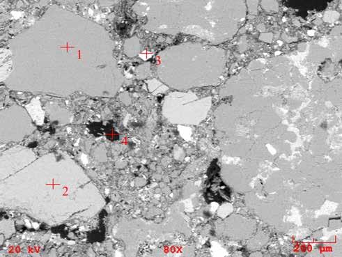
To further study the strength of the mix we prepared a simulation in Karamba 3D, and studied the interaction of sand, water and gravel particles at a microscopic level.
The study of voids was also an important part of the analysis, as it impacted the strength of the concrete directly,

Concrete Section Mix 1 / Core 1 Scale - Microscopic Aggregate
Particle-01 (Large) Particle Size = 1/4” - 1/2” Represents 3 parts of a “standard” mix ratio
Portland
Particle-02 (Small)
Particle Size = 0.007 - 0.2mm Represents 1 part of a “standard” mix ratio
Particle-03 (Medium) Particle Size = 0.074 - 4.75mm Represents 2 parts of a “standard” mix ratio
Right Images: 2D and 3D simulation of partial packing of mix ratios.


GROUP NUMBER: 2
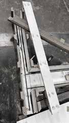
To prepare the form work of the aperture, a variety of materials and layers were used. From melamine coated MDF(3/4” thick) to multiple 2x4s as horizontal, vertical and inclined bracings, utmost precision was exercised.
Member 01: Luke Dole
Member 02: Jackson Gaylord
Member 03: Joshua Kneer
Member 04: Patrick Ma
Member 05: John Mark Silbert Nachbar
Member 06: Ainish Shaileth Sheth
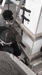
To further make the strength of the structure better, #3 re-bars were used that ran across the lengths, breadths and heights of the form work. Apart from that there was a negative space that was left open/un-poured to make way for the desired aperture.
Member 07: Harsh Thakkar
To increase the strength of the form work and reduce any chance of bulging or deformation a wood exoskeleton was added to the formwork.
The entire cast was anchored to a table in the shop via a frame to increase the stability and safety of the pour.
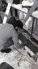
The pour was completed in the upright position instead of pouring on the oor due to concers about lifting the wet concrete and the safety of team mebers.
Caulk was used to seal the joints of the form work due to the wetness of the mixture. Extra water was added to the mix to ensure that the concrete would ow around all the angles and ll in the small tollerance areas.
Mixing 4.19 cuft of concrete for pour
Formwork Reinforcement skeleton to reduce bowing and flexing of MDF
Dry fitting rebar to ensure fit Placing Rebar around positioned Foam Insert
Sealed corners with caulk
Large “A” frame attached to table and straps used to ensure stability of formwork
Foam insert reinforced with wooden dowels for pour
Vibrating formwork to reduce air bubbles and increase particle packing
Image: Form work analysis after concrete pouring process was completed

smooth nish for the aperture. In some places came to the surface. This avoided with additional to different vibration relatively smooth nish course than the nish coated MDF. To avoid this other coating methods insert was spackled and possible, but perhaps paint, coating could have provided mix created a unique some of the smoother desirable in all application, interesting and provided and prototype.
Wet mix left interesting marbled pattern in long vertical surfaces
Wet mix left interesting marbled pattern in some spots
Trapped air bubbles on the top surface of the beam