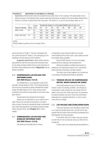
Example 6.1 Specification of Lap Splices in a Drawing Specification: Reinforcement shall not be spliced except where shown in the drawings. The splice length of bars shall be as given in the following Table, except where other dimensions are stated on the actual detail. Spliced bars
shall be in contact or spaced less than 3db apart. The factors k1, k4 and k5 have all been taken as 1.0. Tensile lap length (mm) for grade D500N bars of size (mm)
Type of member
f'c Cover (MPa) (mm)
10
12
16
20
24
28
32
36
Slab or wall
25
20
440
570
830
1130
-
-
-
-
25
400
530
800
1080
1390
-
-
-
40
360
440
680
960
1260
1590
1920
2310
50
360
440
610
880
1180
1490
1840
2210
Other main bars
25
NOTE: All lap lengths rounded up to the nearest 10mm
outermost bars of ‘Sheet 1’ have not overlapped the
complicated, uses excessive steel, and causes
two outermost bars of ‘Sheet 2’, the overhangs do not
overcrowding of the column area. Such splices should
contribute, and the splice is NOT CORRECT.
be avoided where possible.
Suggested specification: Mesh sheets shall be lap-spliced so that the two outermost transverse bars
See AS 3600 Clause 13.2.5 for the design requirements for splicing main bundled bars.
of one sheet overlap at least the two outermost bars of
Wherever possible, bundled bars should be
the other sheet. (Sketches similar to Figure 6.5 may be
spliced by end bearing (no laps) or by a mechanical
added if desired).
splice because these give a simpler solution. Two bars may be tied together as a bundle but
6.10
COMPRESSION LAP-SPLICES FOR
no increase in development length is specified.
DEFORMED BARS (AS 3600 Clause 13.2.4)
6.12
For D500N bars in a compression zone of the Accessed by Arcadis on 11 Aug 2017 (Document currency not guaranteed when printed)
TENSION SPLICE OR COMPRESSION SPLICE, WHICH SHOULD BE USED?
concrete, the lap length is 40db. This is approximately
The simple answer is that if a bar can be in
two times the compressive stress development length.
tension under one loading condition, and change to
Under AS 3600 Clause 13.2.4, there are two other
compression under another (or vice versa), then the
conditions that reduce the lap-splice to 0.8 of the value
splice must carry the “worst-case” load. As examples,
given above.
the above situation can occur when the wind blows
Compression bars should not be hooked.
alternately from opposite directions, or when trucks
Values are not restricted to use in columns and
move across a bridge.
walls. Where the concrete at the bottom of a beam over a column carries an excessively large compression load, extra bars lapped for compressive stress transfer will be required there. (See Chapter 13 on beam cages).
6.13
LAP SPLICES AND OVERLAPPED BARS There are obviously many situations where there
is no need to transfer stress from one bar to the next, except that the ends of bars should be overlapped and tied together for fixing purposes.
6.11
COMPRESSION LAP-SPLICES FOR
In the latter case, the overlap may only need to
BUNDLED DEFORMED BARS
be 100-150 mm for a small bar and up to 300 mm for
(AS 3600 Clause 13.2.5)
a large bar.
Lap splicing of bundled bars is messy,
In each case, the overlap should be specified in
6:11 Reinforcement Detailing Handbook
Chapter 6_jin.indd 6:11
10/11/10 10:09 AM