



From tools to preventive maintenance
ENGINE OIL INNOVATIONS
DIAGNOSING RIDE CONTROL

Drive


MANY OF YOU PROBABLY ALREADY know that two states have long had a law that prevented drivers from pumping their own fuel (Oregon and New Jersey). Just recently, Oregon changed their law to allow selfserve. (As I understand it, half of a station’s pumps would remain full-service while the other half would allow selfservice.) Finally, a bit of common sense prevailed in Oregon. However, New Jersey remains the sole holdout.
I’m uncertain of the goal with regard to preventing drivers from adding fuel to their own vehicles. Perhaps it’s a concern about “safety” and to prevent over-filling which could result in fuel being spilled onto the ground. If that’s the reason, I assume that the New Jersey “brain trust” figured that if they allowed only “professionals” to perform the task, the situation would result in greater safety and would help to protect the environment. I also candidly wonder if an underlying reason for this is to help boost the state’s automotive repair business.
Why do I say this? Let me relate a true story. A few years back, my shop had performed a total restoration of a 1968 Plymouth Satellite convertible. (It was a horrible job — one of those cars you’re happy to be done with and forget.) Once the job was completed, the owner, who resided in New Jersey, requested to have the car delivered to his house. Since it was difficult for me at the time to be out of the shop for about two days, one of my technicians volunteered to make the drive, using my Ford F-350 dually crew cab turbo diesel truck and one of my trailers. After delivering the car, he decided to top off the tank before heading home. He stopped at a New Jersey gas station only to discover that he was not allowed to pump the fuel himself. He told the attendant to fill the tank with diesel fuel. He repeated his request several times — “diesel fuel.”
While my driver sat in the truck playing with his phone and studying a map, he noticed the unmistakable odor of gasoline. Out of curiosity, he exited the truck and walked around to the pump, only to discover, to his horror, that the “professional” was filling the diesel tank with gasoline. I don’t think I need to tell you that this is not a good thing. He immediately ordered the “professional” to stop. I’m certain that a slew of totally
justified expletives were used, as you might imagine. He demanded that the station pump the gasoline out of my truck’s tank, to no avail. Out of sheer frustration and desperation, my driver drove the truck to an automotive repair shop (luckily the shop was directly across the street from the gas station). We ended up paying about $600 to have the tank removed and flushed, and for a fuel system flush. The shop sent a tech to the gas station to buy 10 gallons of diesel fuel to finish flushing the system, and to leave enough in the tank to get into Pennsylvania for a proper fill-up. The repair shop’s owner noted this was not an uncommon situation, telling my driver that it “happens a lot.” Luckily, my truck’s engine suffered no permanent damage. Imagine if my driver hadn’t caught the mistake and continued on his return trip. I can only guess how many miles would have been driven before the engine said, “I’ve had enough.”
As a result of New Jersey’s fuel service laws, the New Jersey-based repair shop gained more business. Coincidence? Obviously, the repair shop wasn’t to blame. Based on our experience, I began to wonder how many similar scenarios have occurred where gasoline was added to diesel engines and/or diesel was added to gasoline engines. Either case would immediately or eventually result in more repair business by the state’s repair shops. Again, no blame is placed on the shops. Thanks to what I consider an idiotic law, an unknown percentage of vehicle owners have been forced to pay for repairs that were avoidable.
On the good side, the state’s repair shops benefit from the added business. It’s an example of how some laws result in both negative and positive results. In this instance, we have those well-meaning New Jersey politicians to thank for that.

 MIKE MAVRIGIAN EDITOR


THE TECHNICIAN’S RESOURCE
3515 Massillon Rd., Suite 200, Uniontown, OH 44685
(330) 899-2200, fax (330) 899-2209
Website: autoserviceprofessional.com
PUBLISHER
Greg Smith / gsmith@endeavorb2b.com (330) 598-0375
EDITORIAL
Editor: Mike Mavrigian mmavrigian@endeavorb2b.com
Managing Editor: Joy Kopcha jkopcha@endeavorb2b.com / (330) 598-0338
Associate Editor: Madison Gehring mgehring@endeavorb2b.com / (330) 598-0308
PRODUCTION
Art Director: Molly VanBrocklin
Production Manager: Karen Runion krunion@endeavorb2b.com / (330) 736-1291
CONTRIBUTORS
Jeff Taylor, Diagnostics & Drivability Specialist
Bill Fulton, ASE Master Tech
Craig Van Batenburg, EV Technology
ADVISORY BOARD
Chris Chesney, Repairify
Jake Sorensen, McNeil’s Auto Care
Seth Thorson, Eurotech Automotive

Donny Seyfer, Seyfer Automotive
Bill Fulton, ASE Master Tech
ACCOUNT EXECUTIVES

Marianne Dyal / mdyal@endeavorb2b.com (706) 344-1388
Sean Thornton / sthornton@endeavorb2b.com (269) 499-0257
Turn to it any time you need the latest technical service bulletins, in-depth technical articles and the newest products. Our site also features news from suppliers and manufacturers to keep you up-to-date on what’s happening in the automotive industry.
Plus, go to our website to renew your subscription to ASP, read the digital version of each issue and sign up for a free subscription to our weekly eNewsletters!
Kyle Shaw / kshaw@endeavorb2b.com (651) 846-9490
Martha Severson / mseverson@endeavorb2b.com (651) 846-9452
Chad Hjellming / chjellming@endeavorb2b.com (651) 846-9463

CEO: Chris Ferrell
President: June Griffin
CFO: Mark Zadell
COO: Patrick Rains
CRO: Reggie Lawrence
Chief Digital Officer: Jacquie Niemiec
EVP Transportation: Kylie Hirko
Vice President - Vehicle Repair Group: Chris Messer
VRG Editorial Director: Matthew Hudson
Some 2015 Ford F-150 trucks equipped with EPB (electronic park brake) and built on or before Feb. 21, 2015, may exhibit a parking brake malfunction message, a yellow park brake indicator and a flashing red brake warning indicator when activating the parking brake. DTC U3000:49 may be stored in the EPB module. Connect a scan tool to the DLC. If codes other than U3000:49 are stored, address those codes first before continuing. If DTC U3000:49 is still stored, replace the EBC module with P/N FL3Z-2C496-B.
If you have a customer with a Ford E-250 van equipped with an automatic transmission, and the customer thinks the transmission failed because it suddenly lost drive power, don’t jump the gun. It may be a broken or failed flexplate. We recently had a 2006 E-250 get towed in with the same complaint. After removing the access cover, we discovered we could rotate the flexplate by hand. The flexplate had fractured around all of the bolt locations and had fully separated. Within 2.5 hours, we pulled the transmission, replaced the flexplate, reinstalled the transmission and sent the customer away happy — since he was anticipating needing a new or rebuilt transmission. Of course, this can apply to other vehicles, too.
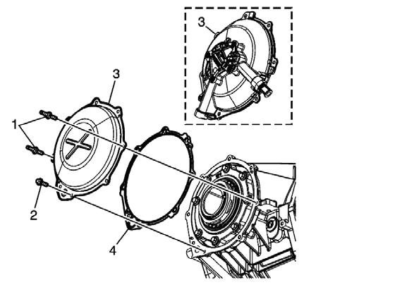
Owners of a 2014-2019 Chevy Corvette, equipped with a 6.2L engine and 8L90 automatic transmission — and not equipped with electronic positraction limited slip — may complain about a “warbling” noise at the rear when operating in the 1,500 rpm range when traveling up a slight grade. This may be due to the bushing in the left side differential cover having excessive clearance. The fix involves replacing the left side rear axle housing cover with P/N 84705711.
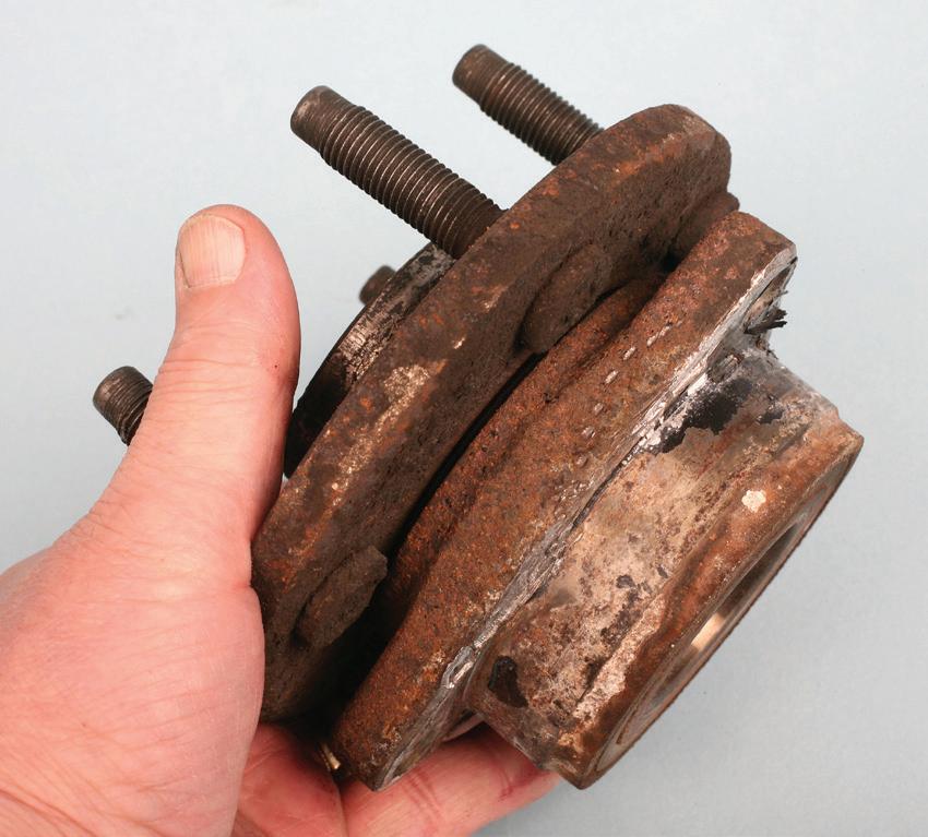
Whenever you encounter a suspension system that features iron or steel components that directly contact aluminum components, a galvanic reaction is inevitable: the two dissimilar metals will corrode together and likely make future disassembly very difficult. The same applies to alloy wheels mounting to steel/iron hubs. During service (once disassembly has taken place), clean both surfaces thoroughly and apply a thin application of lubricant on the mating surfaces. High temperature antiseize paste is a common choice. Where steel bolt threads enter aluminum, the same principle applies. Coat the threads with an appropriate-strength thread sealant or lubricant, depending on the application requirements. Also, apply a thin coating of lube/grease to the underside of the bolt heads.
If you have a customer who complains about a noise and/or vibration that is heard/felt at the rear of a 2007-2015 Mazda CX-9 AWD vehicle, the cause may simply be worn or brittle rear differential mounting bushings. Due to the close proximity of the exhaust pipe, the rubber may become hardened and cracked. Mazda has improved the rubber to make it more resilient to heat damage. Order P/N L214-29-68XB for the right side and L21428-68YB for the left side. Torque the new differential rubber mount bolts to 47-62 ft-lb.


 BY CRAIG VAN BATENBURG
AT ACDC, WE HAVE BEEN IN THE Electric and Plug-in Hybrid technician training business literally since the first affordable (under $45K) plug-ins hit the market in 2010, the Chevy Volt and Nissan Leaf. Tesla came out with their electric roadster a couple years before, at a price of $100,000. With our shiny new Chevy Volt, plugging in a car was now a thing. Nissan Leaf was the next ACDC purchase at about the time the Tesla Model S was sold. When the Model X came out, my company leased a Chevy Bolt, then bought a Kia Niro EV about the time the Model 3 was launched. Why did ACDC stay away from Tesla all that time? No factory scan tool. Was I personally interested in them? Somewhat, but a chance meeting changed my views.



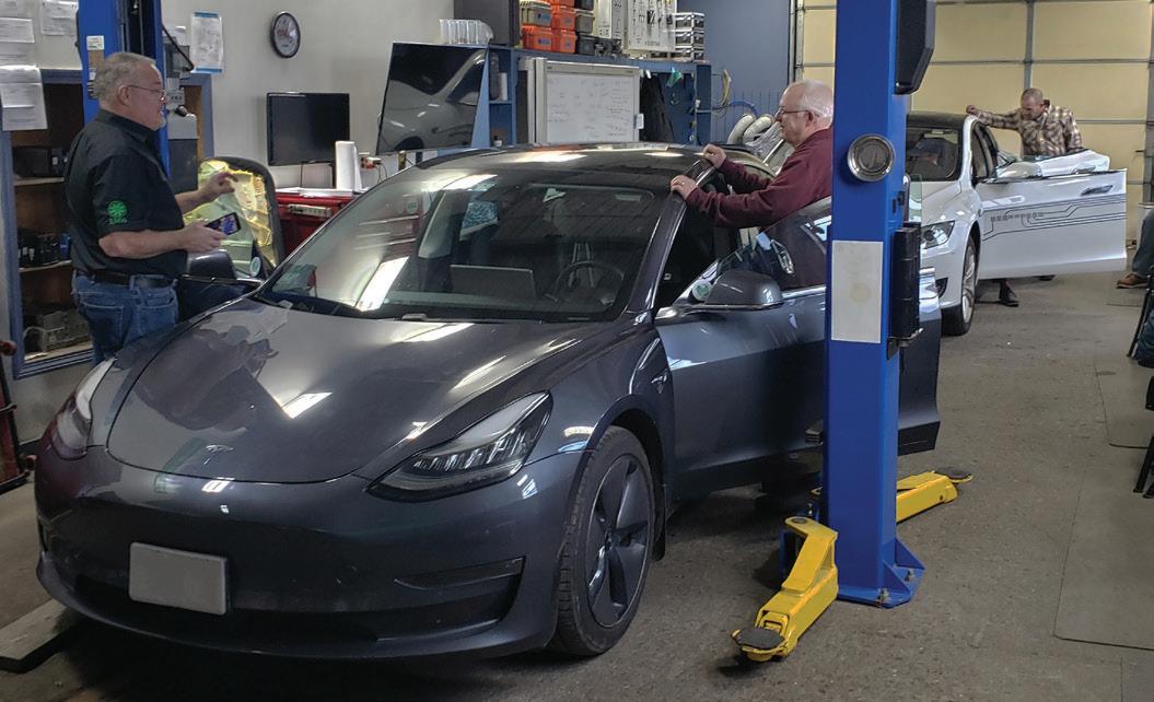
Let me introduce Aiden Neary. Aiden works at ACDC. I met him at an electric car show when he was 17 years old. His father, Robert Neary, showed up in a dirty 2013 Tesla Model S with wires hanging out of the dash, so I stuck around until the owner showed up with Aiden in tow. Aiden, a self-proclaimed “geek,” grew up in his father’s EV. The two of them took a class we offered on high voltage battery technology and Aiden impressed me with his knowledge. Robert and I talked about me hiring Aiden part time when he was a senior in high school. Aiden was a natural. College is in Aiden’s future, but for now he is having fun, traveling and holding court all over the USA at ACDC Tesla classes. At the










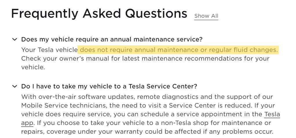
ˇ Does my vehicle require an annual maintenance service?
Your Tesla vehicle does not require annual maintenance or regular fluid changes. Check your owner’s manual for latest maintenance recommendations for your vehicle.
ˇ Do I have to take my vehicle to a Tesla Service Center?
With over-the-air software updates, remote diagnostics and the support of our Mobile Service technicians, the need to visit a Service Center is reduced. If your vehicle does require service, you can schedule a service appointment in the Tesla app. If you choose to take your vehicle to a non-Tesla shop for maintenance or repairs, coverage under your warranty could be affected if any problems occur.
Tesla says their vehicles do not need annual maintenance.
• Brake fluid health check every 2 years (replace if necessary).

• A/C desiccant bag replacement every 4* years.
• Cabin air filter replacement every 2 years.
• Clean and lubricate brake calipers every year or 12,500 miles (20,000 km) if in an area where roads are salted during winter.
• Rotate tires every 6,250 miles (10,000 km) or if tread depth difference is 2/32 in (1.5 mm) or greater, whichever comes first.

• *A/C desiccant bag replacement can be extended to 6 years on vehicles manufactured between approximately 2017-2021.
Tesla also tells their customers that preventive maintenance is needed, some of it often.
young age of 22, Teslas are in his blood. My thanks to Aiden for his help in writing this article.
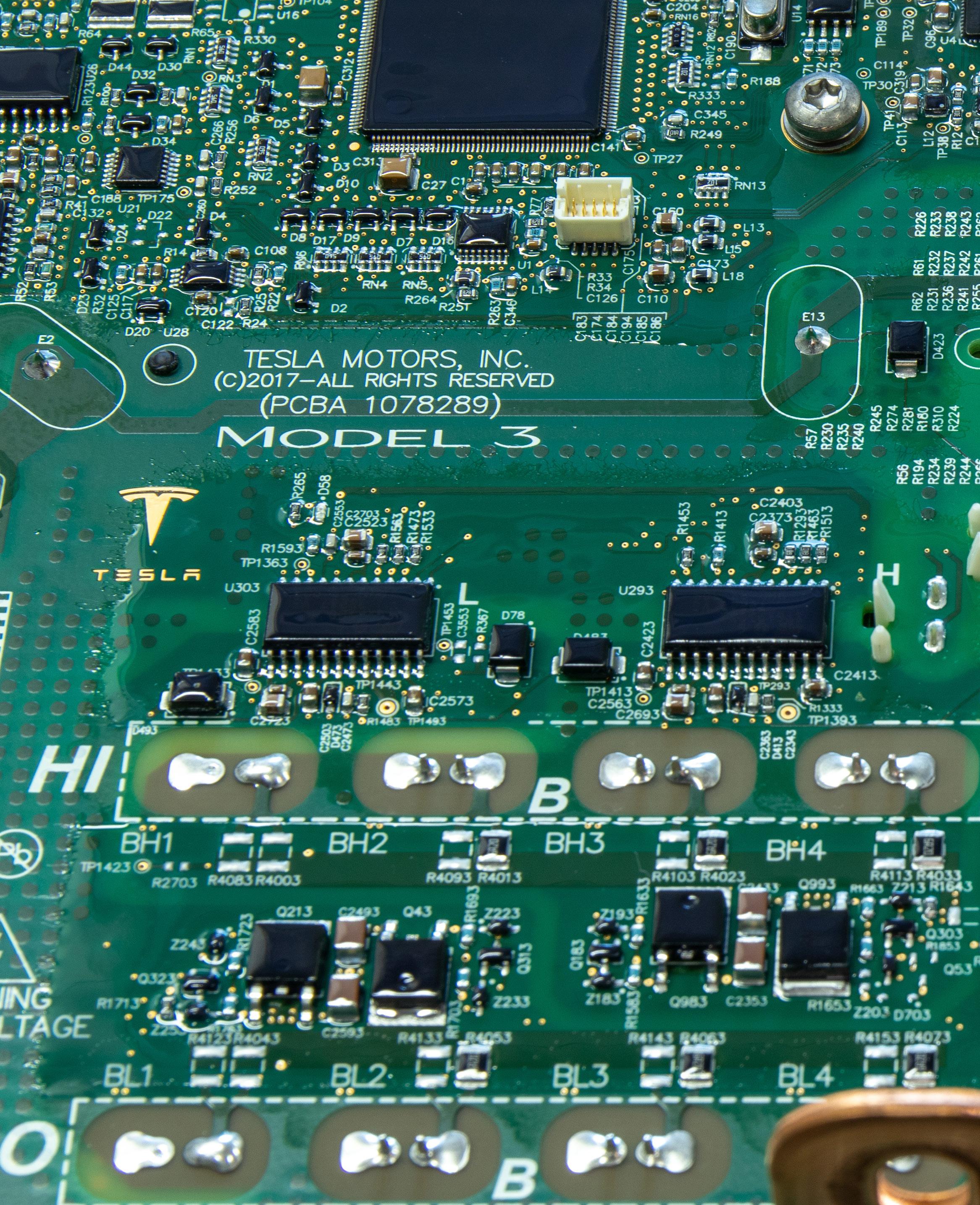
In late 2021 Tesla released “Toolbox,” a Tesla vehicle scan tool of sorts. This was the first public sign that Tesla had overplayed its hand and needed the aftermarket shops to bail them out. The writing was on the wall for quite some time that selling almost a million cars in 2021 and not expanding their service centers would end up with many unhappy Tesla owners. This also had a negative effect on the employees who worked at the Tesla repair shops. ACDC coined the word “EMV” when hybrid cars added plugs and EVs come into the marketplace, around 2010. At that time Tesla had an electric roadster and the Model S was under development. EMV is used to describe any high voltage vehicle, be it hybrid (HEV), plug-in hybrid (PHEV), electric vehicle (BEV or EV), EV with range extender (EV-RE), fuel cell vehicle (FCEV) or a plug-in fuel cell vehicle (FCPEV).
It had always been possible for ACDC to stay up to date with EMV technology so we could offer classes and tech support — until Tesla became a car company. In 2000 ACDC took delivery of a Honda Insight, the first hybrid sold in America. Scan tool, service manuals (yes, books) and tools were available on day one. The National Automotive Service Task Force (NASTF) was created in 2000 and I was fortunate to be at the first meeting
in Las Vegas. In the beginning, we met twice a year, Detroit in the spring and Las Vegas in the fall. Tesla was not a company yet. The focus of NASTF was to ensure that vehicle owners had a choice on where to get their car or truck fixed. In states like Massachusetts (where I live and work) vehicles are tested for safety and emissions, therefore aftermarket shops here must keep up with equipment, service information and training to compete with dealerships. Keep in mind that most of NASTF’s work was emissions related. In 2011 when Tesla came out with their 2012 Model S, it had no tail pipe emissions, so Tesla took a pass on joining NASTF. All other OEMs at that time willingly (or unwillingly) signed a letter of understanding to cooperate with the aftermarket repair industry to avoid legislation. As a result, the OEMs provided factory scan tools, special tools, parts and service information for the aftermarket for a fee. While all this was going on, Tesla was selling more and more EVs.
So much for history. Let us get into what we know now.
Tesla is a bit ambiguous about what they tell their customers in regard to check-ups. (See charts to the left.)
On the same website you will also see suggestions for preventive maintenance (PM).
As you can see, Tesla recommends preventive maintenance when a Tesla service center is nearby, but also tells owners that annual preventive maintenance is unnecessary, unless it is tires or brake service.
ACDC has a generic EV preventive maintenance schedule added to our new EV book. This may be a better approach to suggest preventive maintenance to a new Tesla customer that seeks you out.
Today, if you live in Sidney, N.D., and need service, the closest Tesla service center is more than 600 miles away in Minnesota. Tesla pioneered over-the-air software updates for that reason, as the owner can initiate a software download with a text message to Tesla on their smart phone app. Remember, this was over 12 years ago. If Tesla could convince buyers that their cars needed no preventive maintenance and never broke down, then being 600 miles away from a shop is not a problem, right? Years ago, Tesla had very few service centers and today waiting for service and repairs is common.


ACDC bought a used Tesla Model 3 Dual Motor extended range at the peak of their value (June 2012) and Aiden Neary was elevated to the position of ACDC Tesla instructor. He handled the registration with Tesla once we took delivery. The previous owner did not let Tesla know it was sold, so right away we had a problem. Aiden contacted Tesla in California and they in turn contacted the previous owner and verified that they sold their car. Once that was done, we were able to access the Tesla app on our phones, add a credit card so we could use the Tesla Super Charger network and use our cell phones as keys. If you get into the Tesla service business (which I highly recommend), there are more challenges than just repair and service. You have to take care of the customers too.
Used Tesla EV prices have dropped considerably this year. $20,000 will get your shop a Tesla. Add your name or wrap the car, make a website and get to work. This opportunity will only last for a while.

In the meantime, look for more Tesla articles in the future.
There are three scan tool terms used by Tesla that you need to understand.


“Service Mode” is a limited, built-in scan tool accessed without a subscription. It is free and we will call it “SMF,” or Service Mode Free.

“Service Mode +” is a more in-depth scan tool. It’s also built into the vehicle, but it must be “unlocked” with a subscription to “Toolbox 3”. We will call it “SMP,” or Service Mode Plus.
“Toolbox 3” is a laptop-based scanner that is used when in SMP to do most programming and active tests. We will refer to this as “Toolbox.”




ACDC’s electric vehicle preventive maintenance schedule.

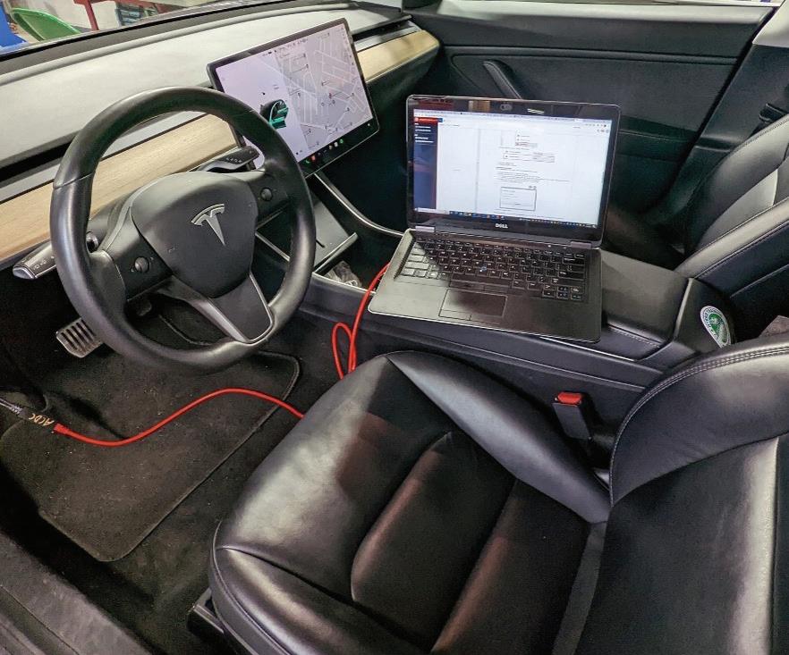
To keep things simple, I’ll define the “Factory Scan Tool” as the combination of SMP and Toolbox (web application, not a download). Toolbox works by using a five-pin connector on the car to an ethernet cable (ETH) on your laptop, and it enables you to communicate and send commands to the vehicle for servicing. An example would be retracting the rear parking brakes so that you can install a new set of pads when servicing the rear brakes. SMP is just a software feature in the vehicle that is accessed by paying for Toolbox.


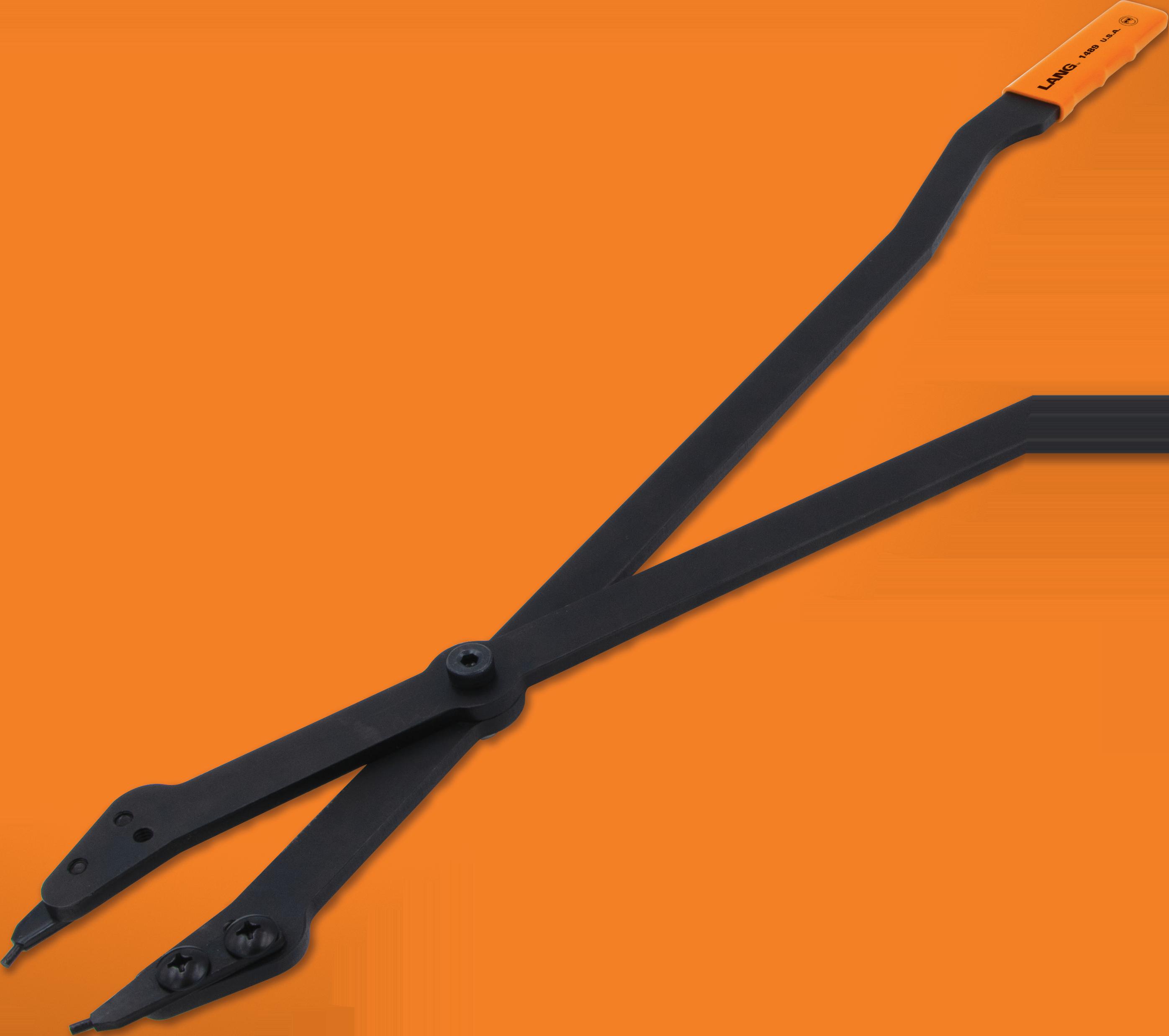
Heavy duty pliers used to remove and install the large internal retaining ring in transmission cases
26" handles provide the leverage needed to compress large retaining rings
For use on GM 5L40, 5L50, 6L45, 6L50, 6L80, and 6L90 transmissions





Straight .120" diameter interchangeable tips GIVING YOU THE LEVERAGE YOU NEED


#1489

Since Tesla uses a diagnostic connector to access information being reported in the vehicle, the car can talk with your laptop in the same language and be given a “Key” to unlock SMP on the center screen. The “Key” being used here is a series of lines of code sent from your laptop to your car that you paid Tesla for in the form of the Toolbox web application.
Because Tesla did not design and build a traditional hand-held scan tool or a laptop-based scanner, Toolbox and the center screen acts as the scan tool. The information about the vehicle’s onboard systems and their status are displayed on the center screen. Tesla used a 16-pin OBD port for the first few years.
SMP is a mode that is commanded by Toolbox (your laptop), for servicing the vehicle. Many service procedures and some reprograming can be done without Toolbox for free using the built-in factory software (SMF). Toolbox is available to purchase from Tesla to anyone who is willing to pay for it. It is needed for most reprogramming and active testing.
The center screen becomes your handheld scanner equivalent. Once you put the car into SMP by logging into your Toolbox account, plugging your laptop into
• Most owners use their cell phone as a key, so remind them to bring their “key fob” with them.
• The owners have access to all their previous service work done by Tesla. Ask them to email the Tesla repair reports to you when they make their first appointment.
• Tell the customer that their Tesla app will have a limited view and will restrict communication once you put the car in “Service Mode.”
• When making an appointment, schedule enough time for parts and analytical work.
• If a reflash is required, make sure the customer knows a minimum fee of at least a one-day Tesla subscription will be charged. Some preventive maintenance, like a brake fluid flush, will require a factory scan tool.
the vehicle’s diagnostic port, and commanding it into SMP, you can view live data, perform basic procedures such as a software reinstall, brake burnishing mode, HV Battery discharge function, and many more. Once in SMP, the customer no longer has control of their Tesla with their phone. You can only put the car into SMP if you have an active subscription for Toolbox.
Most simple service procedures can be done with the car being in “SMF,” which is accessed through the vehicle’s screen by going to the software menu, holding your finger on the car’s Make and Model button, and then typing in “service” when prompted. Toolbox and SMP only come into the picture for heavy diagnostics or repair. You will get better live data lists, more menus, more buttons, control module reprograming, active tests and functions for every electronically controlled component in the vehicle. Like all scan tools, there is a learning curve.
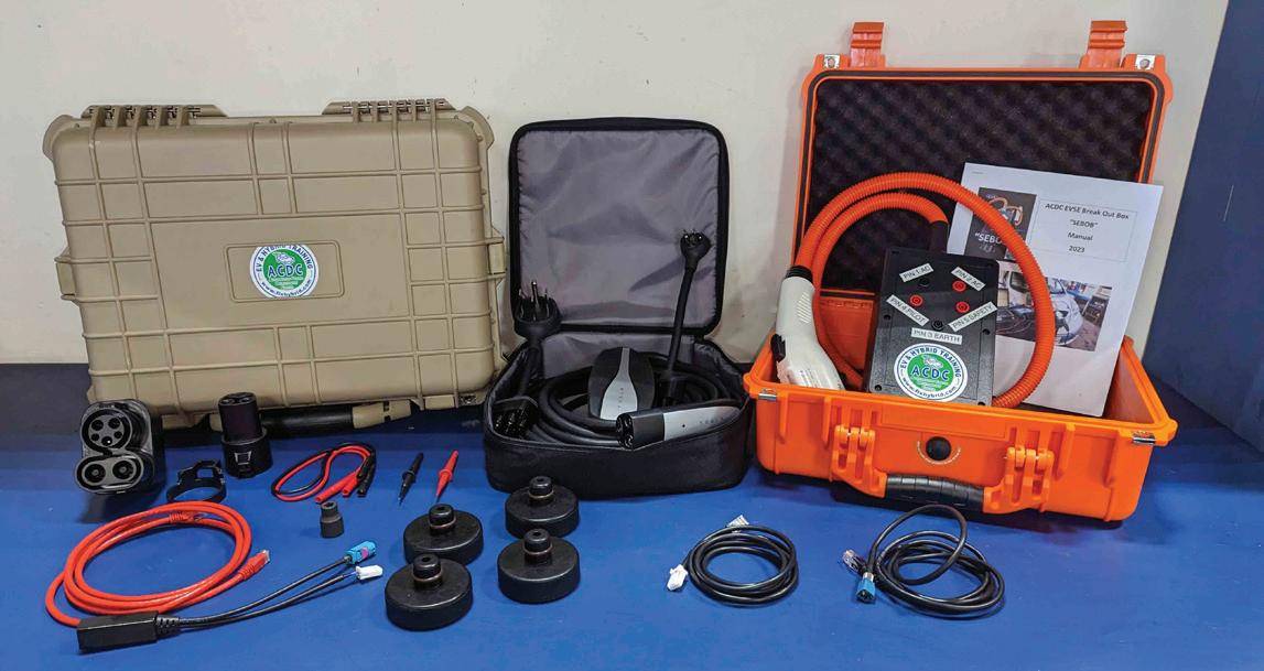
The factory scanner is $3,000 per year — or $500 per month or $165 per day. Most service tools are under $2,500 for 90% of what you need. This assumes you are a full-service repair shop. Many Euro shops are calling us as they are losing their customers to Tesla, so we stock a “Tesla service kit” that helps you get into Tesla service.
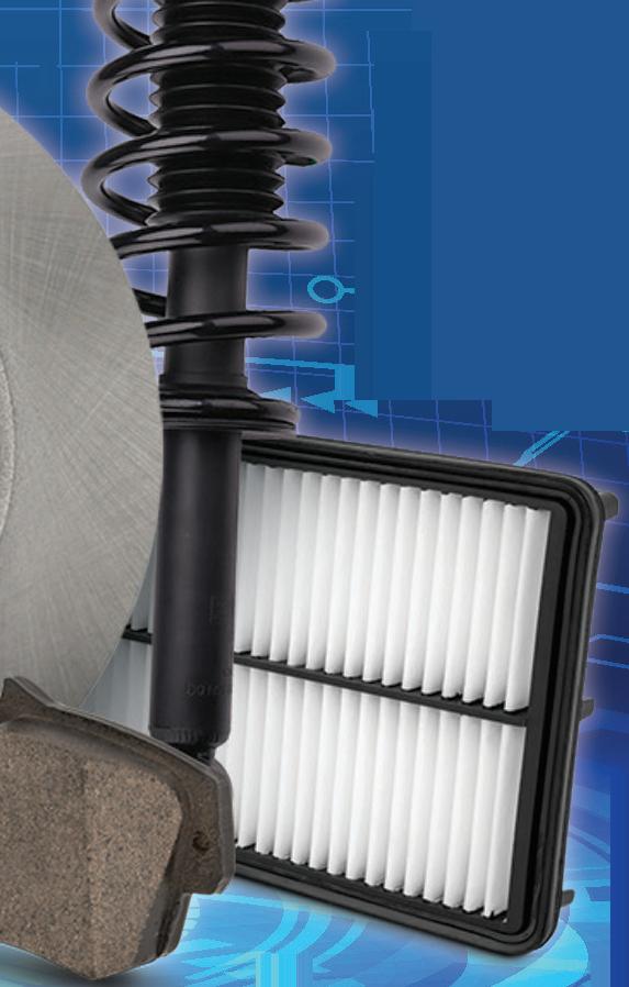
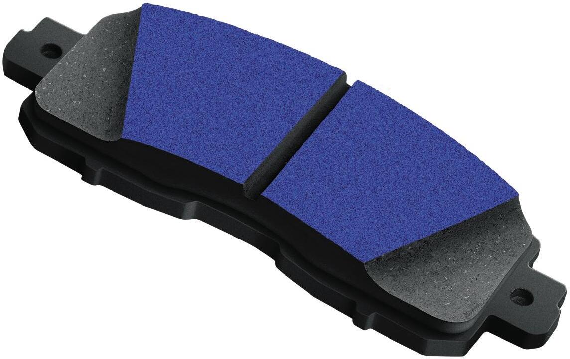
BREAK-IN COATING
Increases braking contact for better stopping performance

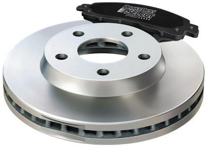
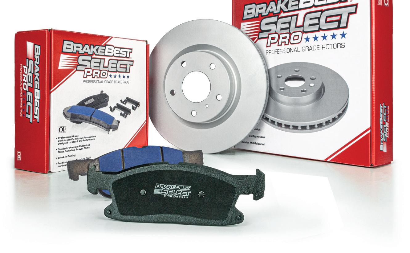
OE-STYLE CHAMFERS & SLOTS
Maximizes heat dissipation & minimizes noise
OE-SPECIFIC FRICTION FORMULATIONS
Delivers safe, reliable performance

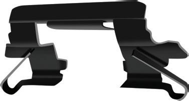
PTFE & RUBBER COATED HARDWARE*
Reduces vibration & noise while preventing binding to caliper

*Included where applicable
5-LAYER STEEL & RUBBER SHIM
Silences noise & vibration
ENGINE OIL HAS BEEN AROUND a long time, and we all know the importance of it, yet it is often one of the most undervalued elements in a vehicle. Some techs don’t like checking it, changing it or spending the time that is now required to ensure that the correct engine oil is being installed in the vehicle they are servicing. But the engine oil that is being used today, especially in a new or brand-new vehicle, is a highly specialized and developed product.
When we think about engine oil, the first thing that usually comes up is the correct viscosity that is needed for a particular engine. But viscosity is only a small part of the huge chemical compound that we identify as engine oil. Low viscosity oil is now the norm. 0W-based oils offer improved cold start circulation, reduced engine drag when starting, lower fuel consumption and they allow the engine to produce lower exhaust emissions. But these low viscosity engine oils also allow more flow through the engine when it’s at operating temperature, providing the needed lubrication, friction reduction, cleaning and cooling properties that engine oil must provide.
There are three common engine oil-based concerns that the OEMs and the major manufacturers of engine oils are addressing:
• Crankcase moisture deposits.
• Soot.
• LSPI: Low-speed pre-ignition.
Crankcase moisture has long been a concern in the internal combustion engine (ICE), but what causes it? It is most often visible on the oil cap as a thick, milky slime. Condensation from infrequent driving or short trips, high moisture content fuels (such as high ethanol content fuel), seasonal weather changes, PCV issues, a faulty thermostat, or a failed cooling system that allows coolant into the engine are all common causes of moisture (water) entering the engine oil.
Not driving enough is a frequent cause of excessive condensation accumulating inside the engine. If
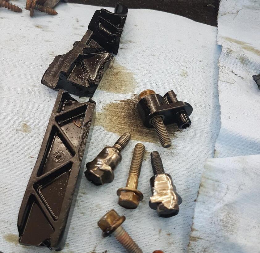
Moisture created inside the engine will become emulsified and mixed with the engine oil forming a familiar white sludge. The sludge can build up as engine deposits, increase the formation of acids and damage engine components. (all photos by author)
the engine doesn’t reach the proper operating temperature, the moisture/condensation that has formed inside the engine will not evaporate and be dealt with by the PCV system and burned in the combustion chamber. The typical short trip is less than 10 minutes — not nearly enough time to fully warm things up, especially in a cold weather climate.
Moisture in the air (humidity), moisture from ambient temperature changes (warm to cold) and moisture created as a by-product of combustion will condense on the surfaces inside the engine. This moisture will eventually find its way into the oil pan and once in the oil pan, it will be mixed with the engine oil and circulated through the engine. If there is enough moisture, we can see issues that range from illuminated dash warning lights to more severe cases that can result in excessive engine wear or worse.
The OEMs and lubricant manufacturers have long been aware of crankcase moisture formation, but the rise in popularity of hybrid vehicles has brought the issue of internal engine moisture formation and its effects on the engine’s oil to the forefront.
Hybrid vehicles typically function at lower engine operating temperatures while the vehicle is in electric


or battery mode. Hybrids perform more frequent stopstart operations and may not reach the best engine operating temperature needed to evaporate the crankcase moisture for extended periods of time. The average hybrid engine can run at least 68 degrees below the operating temperature of the non-hybrid ICE engine. The combination of these events enables crankcase condensation formation. This crankcase condensation will ultimately mix with the engine oil during normal engine operation, becoming combined or emulsified. With hybrid vehicles on pace to outsell traditional ICEequipped vehicles by the end of this decade, both the OEMs and the oil lubrication companies have developed ways to deal with the unique hybrid operational characteristics and the engine moisture it creates.
Oil and water don’t mix, but the engine oil will have emulsification additives incorporated into its additive package that will allow the water and oil to form an emulsion. This emulsion still needs to supply the needed lubrication and protective benefits that the engine’s oil is intended to provide.
The emulsification performance of today’s engine oils is a balancing act of combining and then stabilizing/holding the collected moisture with the engine oil and allowing it to evaporate once the engine oil temperature is high enough. This balancing act is crucial for engine longevity and durability.
The familiar white sludge that we see on the backside of the oil cap is about 40% water by weight and is an example of an emulsification package that could be holding the moisture too well. There are other reasons that can cause the buildup of this white “mud”: bad thermostats, defective cooling systems and internal engine coolant leaks. But this white sludge also shows that circumstances are favorable in the crankcase for increased acid formation that can cause engine bearing corrosion and increased oil pump wear.

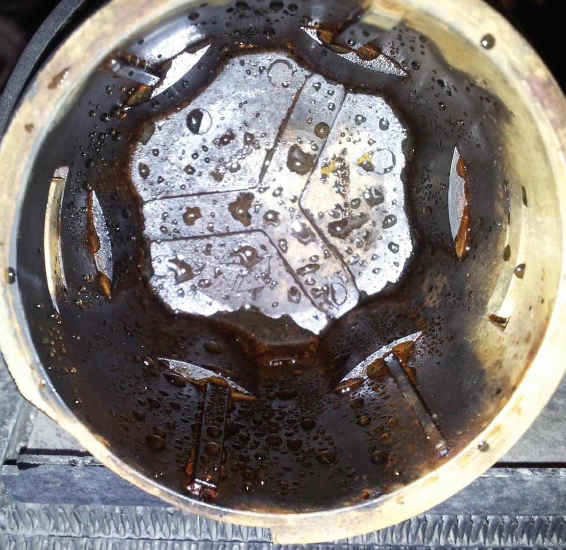
On the other hand, if the emulsification package isn’t holding the moisture well enough, it can allow the moisture to separate out of the oil as water. If the separated water in the crankcase reaches excessive levels, water could cover the oil sump and cause oil starvation, with water being pumped rather than engine oil, or it could cause a freeze, totally blocking the oil pump’s pickup screen, again causing oil starvation.
Several manufacturers have issued TSBs that address the amount of accumulated moisture in the engine oil.
Inside every Standard® and Blue Streak® box, you’ll find the results of advanced research, precision manufacturing, and detailed lab testing and validation. Our parts are also tested on vehicles to make sure they perform in all conditions and integrate with the complex electronic systems of modern vehicles. We also support technicians with sales and technical support and the industry’s most awarded and recognized training programs. That is what’s in our box.


Toyota TSB-0104-21 addresses such an issue, on the hybrid and non-hybrid Dynamic Force A25 or M20 engines. The TSB says the following: during freezing temperatures, low oil pressure DTCs P05202A and/or P052477 could be set, low engine oil pressure warning light illuminated, and a milky discolored engine oil could be seen. The TSB goes on to explain that moisture from the engine blow-by gases can build up because of short trips in extreme wintry weather. When the moisture freezes, the engine oil pressure may drop, setting the trouble codes and illuminating the warning light. The fix is to inspect for internal coolant leaks and if none are found, clear the DTCs and change the engine oil and filter.

Soot is a common byproduct of the Gasoline Direct Injection (GDI) system. GDI supplies greater power, better fuel efficiency and allows for higher compression ratios, but it also creates a harsher environment for the engine oil. When the engine is equipped with a turbocharger that only makes the problem worse. The GDI system can change the viscosity of the engine oil due to the system’s operational characteristics, the increased cylinder pressures, and higher sustained combustion temperatures.
The GDI system produces soot during the combustion process, and this GDI soot is a problem. The traditional engine with non-GDI injection created soot in the combustion chamber, and this soot caused the engine oil’s viscosity to increase, and it aided in the formation of damaging engine sludge. The traditional engine oil designed for these non-GDI engines was engineered to deal with this issue and prevent the formation of sludge and stabilize the oil’s viscosity.
GDI soot is a different beast. Because the GDI system atomizes the fuel so efficiently in the cylinders when it is sprayed, it increases the available surface
area of the fuel to burn, and this leads to the formation of GDI-based carbon soot.

GDI-created soot can be deposited on the cylinder walls and then is scraped off into the engine by the piston rings, where it finally ends up in the engine oil. Once in the engine oil, the oil’s additive package will break down, diffuse and encapsulate these soot particles, preventing or limiting them from causing any abrasive engine wear. Some of these oil-captured abrasive particles will be filtered out by the oil filter, but the traditional GDI soot particle is often too small for the oil filter to filter out.
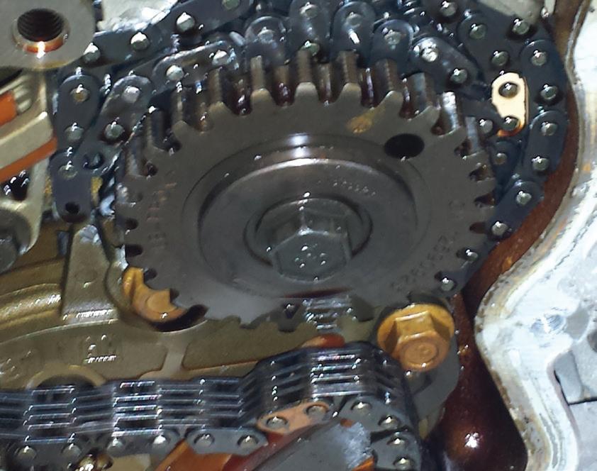
GDI soot will, to some extent, thicken or increase the oil’s viscosity. But because of the different chemical structure and chemistry of GDI soot, it is now linked to the increased wear of various other engine components that typically did not show wear from combustion chamber soot. When GDI soot is combined with the acids and the diluted fuel in the engine oil, GDI soot has been directly linked to the accelerated wear of the engine’s timing chains and other vital engine components.
Fuel dilution, on the other hand, can dramatically lower the engine oil’s viscosity. The fuel dilution can be a result of the GDI system injecting the fuel directly into the cylinders. When the engine is cold, the injected gasoline can condense on the cylinder walls, and like the GDI soot, it is scraped off by the action of the piston rings and into the engine oil.
Fuel-diluted engine oil can accelerate wear on pistons, piston rings and cylinder walls. It also reduces the


engine oil’s ability to stop deposit formation (engine sludge), acid formation, oil oxidation and can lead to higher oil consumption.
LSPI: Low-Speed Pre-Ignition is a random, uncontrolled combustion event that occurs inside an engine cylinder before the spark plug can ignite the air-fuel mixture. LSPI most commonly affects small displacement turbocharged GDI (TGDI) engines under a lowspeed, high-load situation, such as starting off from a stoplight. LSPI can cause loud knocking noises and result in catastrophic engine damage. LSPI is caused by the collision of two pressure waves in the cylinder. When the ignition system fires the spark plug, the airfuel mixture is ignited and causes a planned pressure wave. But when LSPI occurs it will create an unplanned pressure wave, and that’s a problem. When these two pressure waves collide in the cylinder, an enormous amount of energy is released at the point where they meet. This energy causes the loud knock or super knock that is often associated with LSPI, but cracked or de -
stroyed pistons and other devastating engine damage are also common.
What causes LSPI and how is it related to engine oil? When the piston is heading downward during the intake stroke, the GDI injector fires. The injected gasoline will wash the thin layer of engine oil kept in the honing valley marks (for lubrication of the piston rings and the piston) on the cylinder wall. This mixture of engine oil and fuel will become liquified, and will leave a section of the cylinder wall unprotected without any lubricating oil, increasing cylinder wear.
As the piston heads upwards during the compression stroke the liquid mixture of fuel and washed oil will be scraped from the cylinder wall by the piston rings and form small puddles on the top of the piston or between the piston rings and lands. As the piston continues to travel upwards on the compression stroke, the conditions in the combustion chamber can cause this fuel/oil mixture to ignite creating an unintended pressure wave. This is the LSPI event. With the piston still traveling upwards the spark plug will ignite the remaining air/fuel mixture creating the planned pressure wave that will collide with the unintended LSPI pressure wave. When these two pressure waves collide, their energy is combined, and this energy is enough to damage connecting rods, crack pistons, and over time cause sections of the piston to break away completely.
The LSPI problem can be addressed in diverse ways. Ensuring the customer is using the correct octane fuel and keeping the combustion chamber clean and free of any deposits can lower the risks of LSPI. Manufacturers can use the engine management system to over-fuel the engine under certain operating conditions, but that reduces the fuel efficiency of the engine. Reinforcing and strengthening the piston is another way of mitigating the effects of LSPI, but again it can reduce engine efficiency.
An effective way that the OE manufacturers and oil companies have developed to minimize LSPI events is through the development of additives that can be incorporated into the engine oil. These anti-LSPI compounds prevent the fuel/oil mixture from igniting and prevent the unplanned LSPI event from occurring.
Today’s API SN oils, ILSAC GF-6, GF-6A, GF-6B, and Dexos engine oils are formulated with additives to help reduce the risk of LSPI. It’s important to note that LSPI is a complex issue, and while these strate -

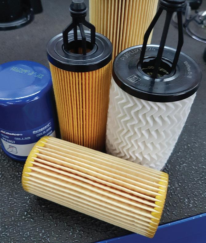
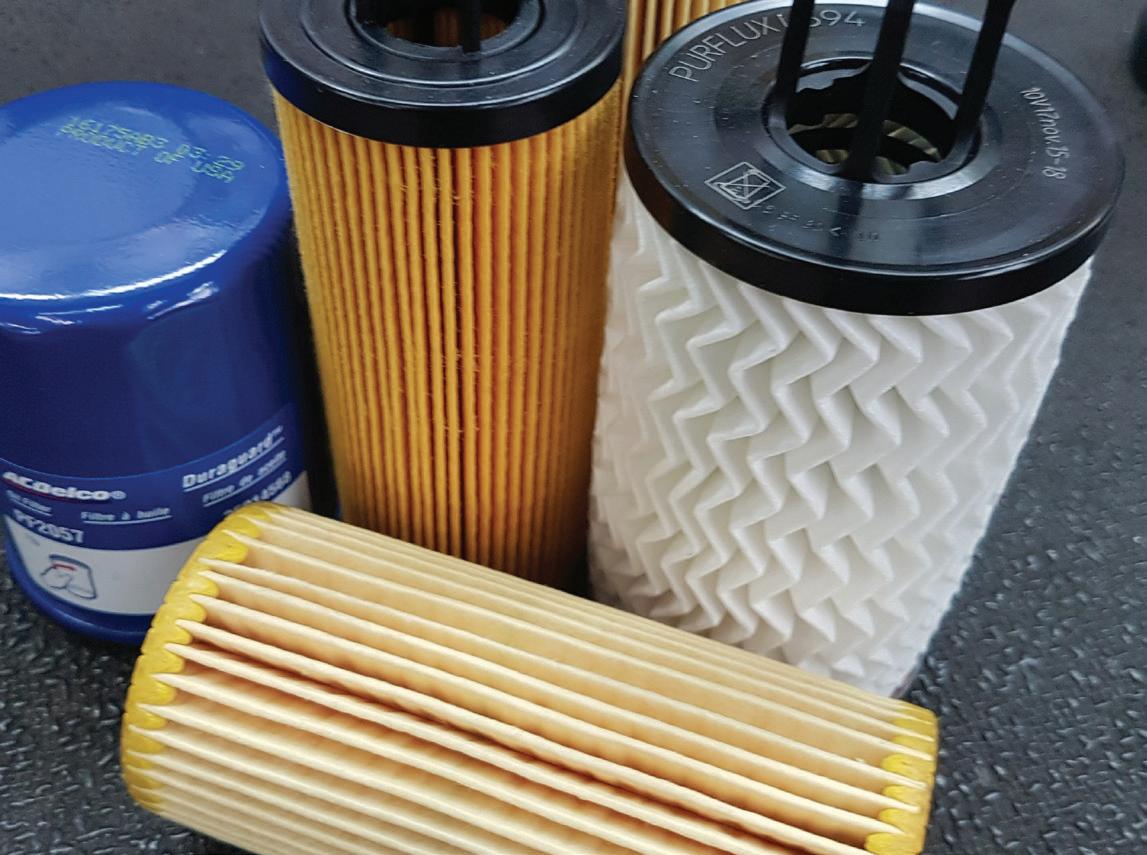
The oil filter is a vital component for the engine, but even the best oil filters have difficulty dealing with all the conditions (moisture and GDI soot) that we can find in today’s engine oil.
gies can help reduce the risk of LSPI, complete prevention may not always be possible.








Engine oil is a continuously evolving product that has become a highly specialized part of today’s vehicles. Gone are the days of the “one oil fits all engines” thinking. Today’s vehicles need highly specific oils that do far more than lubricate, cool, and clean the internal engine components. The engine oil that we use today is highly specific, in some cases even engine specific. It is being asked to perform in a much harsher environment than ever before. And under these extreme operating conditions it is being asked to keep all its initial starting qualities, protections, and capabilities over the extended oil change intervals that we are seeing on today’s vehicles.

Jeff Taylor boasts a 30-plus year career in the automotive industry as a fully licensed professional lead technician. Jeff works for the CARS Training Network Inc. in Oshawa, Ontario, Canada. He is also heavily involved in government focus groups, serves as an accomplished technical writer and he has completed in international diagnostic competitions as well as providing his expertise as an automotive technical instructor for a major aftermarket parts retailer.

ACUSTOMER OFTEN WILL GRIPE about various ride control concerns — vibrations, pulling, noises, etc. However, the customer’s description is often vague or misleading. Attempt to gather as much information from the customer as possible prior to performing an inspection. For example: ‘Do you only hear the funny noise when driving on bumpy roads, or on smooth roads as well?’ If you suspect the vehicle is heavily loaded with cargo at times, ask ‘Does the wandering you experience only occur when heavily loaded?’ The customer’s descriptions of an issue should be considered merely as a starting point. It’s up to you to inspect and road test to determine the actual cause of the complaint.
• The vehicle tends to pull/wander to the right.
• There’s a vibration when pressing on the brake pedal.

• There are noises that seem to be coming from underneath the vehicle as it travels down the road, or when the vehicle goes over bumps.
• The steering wheel vibrates at a certain speed. The customer may also feel that vibration in the seat.
• It seems harder to drive in a straight line, and the issue is getting worse as the vehicle ages and mileage increases.
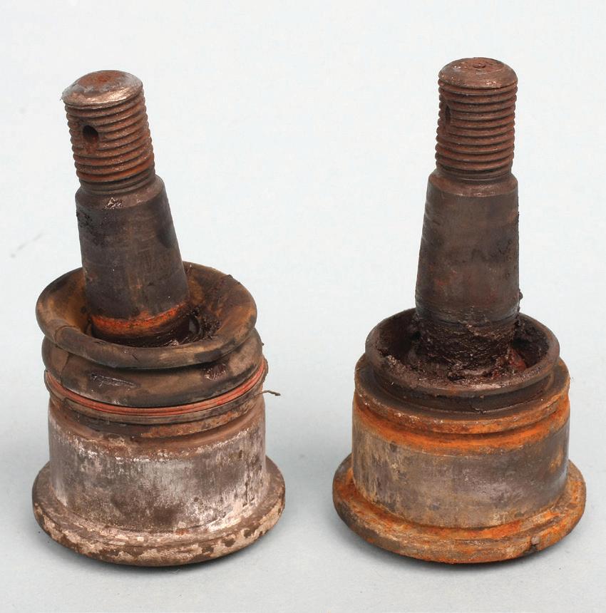
Resist the temptation to diagnose any operational concern at the counter, based only on what the customer tells you. It’s imperative to perform a test drive and inspection to properly diagnose the complaint. Jumping to conclusions opens the door to misdiagnosis. For instance, based on what the vehicle owner describes, you may assume that a wheel alignment is all that’s needed, only to discover later that control arms bushings and lower ball joints require replacement, in addition to alignment. In short, don’t tell the customer what’s needed before performing a test drive and inspection.
Check the basics at the start of any ride control diagnosis by inspecting tire size and inflation, as well as ride height. This initial check can provide a verification starting point or can help to lead you in your diagnosis. Unequal tire inflation can easily lead to a directional pull.
After checking inflation, continue by looking at the tire size — specifically diameter — and verify that both tires on the same axle are the same size. If a previous tire replacement resulted in only one tire being replaced and it’s a different diameter, the smaller diameter tire will cause the vehicle to pull in the direction of the errant side. For instance, if the left front tire features a smaller diameter as compared to the right front tire, the vehicle will tend to pull to the left. Ideally, all tires should be the same make and model, and overall tire diameter should be the same on both sides of both the front and rear axle.










As noted earlier, improper tire inflation pressure is one of the leading causes for a directional pull. Depending on the sensitivity of the suspension design, as little as a 3-5 psi change per axle side can account for a slight pull. The pull will occur at the side that features the lower inflation pressure. The severity of the pull will depend on the comparative difference in the same axle’s tires. Tire inflation differential isn’t limited to the front steering axle only. Uneven rear tire inflation can cause a pull/drift as well.
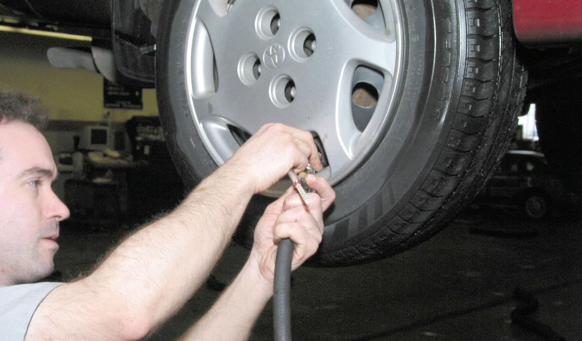
If the tire inflation pressures are correct and the vehicle still pulls, consider swapping left and right side tires. (If the tires are directional, this will require demounting, remounting and balancing). Internal tire construction may be different enough to result in a slight difference in belt reaction to road forces.
Checking vehicle ride height (and comparing your findings to factory specs) can help to quickly identify a potential spring fatigue or failure condition.

Wheel alignment angles can have a profound effect on the vehicle’s tendency to pull in one direction. This includes toe, camber and caster. Excessive toe-out on one side can cause the vehicle to pull in the direction of the side with more toe-out.
If camber angles differ from specification, the vehicle will tend to pull in the direction of the wheel that features more negative — or less positive — camber angle. For instance, if the left front wheel has a camber angle of negative 1 degree, while the right front wheel has 1.5 degree positive camber, the vehicle may pull or drift to the left.
While the caster angle on many common vehicles may not be readily adjustable, uneven left/right caster angle that is beyond specification can easily cause a pull, with the pull taking place at the side with less caster angle. As an exaggerated example, if the left front wheel has a caster angle of 0.5 degree positive and the right front wheel has a caster angle of 2 degrees, the vehicle will pull towards the left.
Brake drag resulting from sticking calipers can cause both an accelerated brake pad and rotor wear issue as well as a directional pull. If the caliper pistons on one caliper do not retract fully (during non-braking or after braking), the pads can retain enough rotor contact to reduce the free-wheeling operation of the rotor and create a pull towards the side with the sticking caliper. Sticking/stubborn caliper pistons can be caused by corrosion in the piston bore as a result of moisture contamination, or following a brake pad replacement after the brake pads were severely worn. If the vehicle was operated with thin pads for an extended period, the caliper piston travel distance within its bore has been limited, with possible rust or contamination building up in the unused area of the piston bore. Once the new pads are installed, the piston(s) can be further retracted while moving within a non-smooth area of the bore. This potentially results in the piston being slowed down or stuck in the contaminated bore area.
If everything seems to check out and you don’t find any obvious causes for the directional pull, consider how the vehicle’s cargo is distributed. If one side of the vehicle is excessively loaded as compared to the other side, this can affect the front wheel alignment angles with changes to toe and camber angles. Granted, the uneven loading would have to be rather severe, but it’s worth considering during the diagnosis.


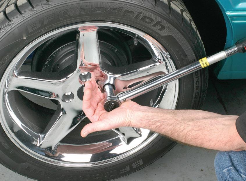
While the use of an impact wrench can speed up wheel installation, the only correct method requires the use of a calibrated torque wrench. Improper wheel fastener tightening can easily lead to hub/rotor warpage, which results in a lateral vibration. This is especially critical when dealing with alloy wheels and many of today’s lighter, thin-hat brake rotors.
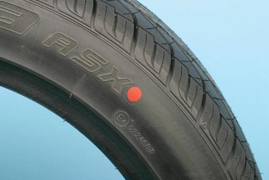
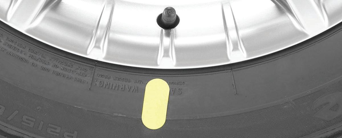
The vehicle may exhibit a vibration felt at certain speed ranges. This is usually an issue involving tire imbalance. Prior to weight-balancing the wheel, pay attention to tire mounting clock position. If the tire features a yellow dot on the sidewall, this indicates the lightest point of the tire. If the sidewall features only a yellow dot, mount the tire so that the yellow dot aligns with the air valve, which will be the heaviest point of the wheel (due to the weight of the valve stem and the TPMS sensor). If the tire features only a red dot, this indicates the tire’s highest radial point. This should be aligned with the wheel’s lowest point. The wheel may feature a reference mark or dimple to indicate the low point of the wheel. If the wheel features no such reference mark, align the red dot to the valve stem. If the tire features both a yellow and red dot, the red dot always takes priority. Aligning these tire dots to specific points of the wheel is referred to as match mounting. Due to the nature of tire construction, it’s nearly impossible to produce a tire that is perfectly balanced or perfectly round under dynamic conditions. These reference dots on the tire allow us to compensate for tire-to-wheel conditions and to help minimize the use of balancing weights.
Also consider how the specific wheels center onto the hubs. Some wheels feature slightly oversized center holes that don’t tightly register to the hubs, and rely on the interface of the wheel fastener holes to the
wheel studs to achieve a centered wheel position. This is referred to as a “lugcentric” design. If the wheel centering takes place between the wheel center hole and hub, this is called a “hubcentric” design, as is common on many alloy wheels today. Be aware that some aftermarket alloy wheels are produced with oversized center holes to allow application to a variety of vehicles. In this case, the hub-centering (hubcentric) goal occurs with the addition of a centering spacer that fills the excess void in the wheel’s center hole and allows proper wheel centering to the hub. When servicing aftermarket alloy wheels, pay attention to this. If the complaint seems to indicate a radial runout issue, the centering spacer may be missing.
If you’ve tried balancing, match-mounting, and have checked radial runout, but the customer still complains of periodic vibration, suspect a radial force variation occurrence of the tire when it’s in a loaded state (when the vehicle is driven). Radial force variation is so named because the radius of the tire varies according to vehicle speed and load. This is the “live” characteristic of the tire, where the tire may have “soft” spots and “stiff” spots in the carcass, tread or in the sidewall construction. Given the high quality control processes used by today’s tiremakers, it’s rare that a force variation problem will occur, but when it does, it can be a tricky demon to chase.

Even though no problems may be found as the tire rotates on the balancer, when the tire experiences a load, the transition of the harder and softer sections of the tire may create a series of harmonic vibrations as the tire contacts and leaves the road surface. Depending on the conditions, this harmonic may occur once per revolution of the tire, or it may occur in a series of vibrations per revolution. It’s possible that this phenomenon may vary according to changes in tire pressure, vehicle speed, individual tire load and the road surface conditions, all of which may serve to reduce and/or amplify the vibration problem. The use of a road force balancing machine can isolate this potential issue. While we don’t have the space here to delve deeply into RFV, our sister publication, Modern Tire Dealer, offers articles that address this subject in detail.





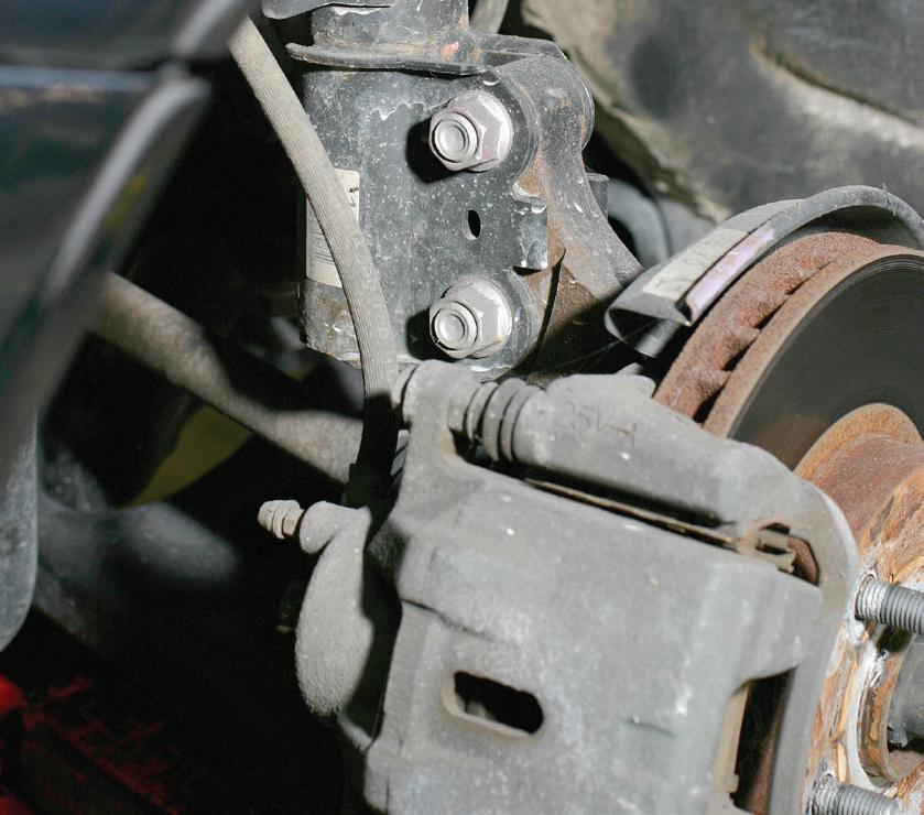
If a vibration and brake pedal bounce occur during braking, the most likely cause is a warped brake rotor, which causes the pads to bounce on/away from the uneven rotor surface. Brake rotor warpage can result from various causes, including brake rotor overheating, lateral or radial runout, sticking caliper pistons and as the result of careless/improper tightening of wheel fasteners. Many passenger cars today feature thin-hat rotors that are easily distorted if the wheel fasteners are unevenly or excessively tightened. This is why it’s important to make use of a calibrated torque wrench, especially when installing alloy wheels. Avoid the use of impact wrenches during wheel installations, and always tighten to factory specifications — following the correct tightening sequence, of course. Wheel nuts (or bolts) must be tightened in a crisscross pattern in order to equally spread the clamping force. Avoid tightening fasteners consecutively in a clockwise or counterclockwise pattern. When installing alloy wheels, especially when dealing with new wheels, be aware that the alloy material may experience slight compressive force when first tightened, and it may begin to relax after a number of miles, reducing clamping force. It’s always a good idea, after the first torque application, to check and retorque after perhaps 50-100 miles of use.
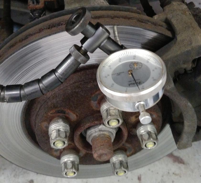
Check brake rotors for lateral runout. Lateral runout causes the rotor to “wobble” as it rotates, kicking the brake pads in and out during braking, resulting in pedal bounce. When checking lateral runout, the rotor must be secured to the hub with all wheel fasteners (not only two or three wheel nuts or bolts), and with fasteners torqued to specification. Mount a dial indicator base to a solid and non-moving surface and lace the indicator plunger perpendicular to the rotor disc surface. Preload the plunger by about 0.05 of-an-inch and then zero the indicator gauge. Slowly rotate the rotor a full 360 degrees and observe the movement of the gauge needle. Compare your reading to factory specifications. Generally speaking, lateral runout exceeding 0.0025 of-an-inch is too much and may require rotor replacement. However, before replacing an otherwise acceptable rotor, mark the orientation of the rotor to the hub (matchmark one wheel stud and its adjacent location relative to the rotor). Remove the rotor and re-position it to the hub in the next clock position and re-check for runout. You may have a stack-up of runout tolerance between the rotor and the hub. If you start to see an improvement, re-position the rotor to the next clock position and re-check. It may be possible to find that “sweet spot” where hub runout and rotor runout cancel each other out.
Loose lower strut mount fasteners can also contribute to a wandering complaint and can affect uneven tire wear. Whenever replacing struts, even if the vehicle design does not theoretically permit camber adjustment, any tolerance space between the bolts and holes can result in improper camber angles. Always perform a front wheel alignment when struts are replaced.
One of the inspections that may be performed when diagnosing a brake pulsation, shimmy or directional control issue involves checking for lateral runout. When checking a rotor for lateral runout, set up a dial indicator and slowly rotate the rotor a full 360 degrees, noting changes in runout. Note: in order to simulate the stress of an installed wheel and to obtain correct readings, all wheel fasteners must be installed and torqued to specification.
If, during initial inspection, you observe a discolored rotor, this is a sign of an overheat condition, which could be caused by several factors, the most likely of which is poor braking habits by the driver. The driver may have a habit of excessively riding the brake pedal and/or abusing the brakes by nailing the brake pedal at the last moment during stops instead of applying moderate pressure prior to final stopping. Or, the brake pads may be the wrong choice for the application, requiring excessive brake pedal pressure. Upgrading the pads to a more robust pad material may solve the issue. Of course, if the rotor is glazed and/or heat checked, the rotor(s) must be replaced as well. If the application involves an emergency vehicle, such as an ambulance or police vehicle, only heavy-duty, high performance pads (for instance, a ceramic metallic compound) that are designed for fade-free panic stopping should always be installed. In short, fit the pads to match the application.
A “noise” complaint has the potential to cover quite a lot of ground. Try to obtain more detailed information from the customer. What type of noise is heard? Clicking, groaning, grinding, popping, whirring, whistling, chirping, banging, etc. When is the noise heard? While starting the engine, or when cruising, braking or turning?
Worn front wheel bearings will typically produce a grinding or clicking sound. Worn or damaged upper strut bearings will typically produce grinding, squeaking or popping noises best heard during slow turns. Worn or dry CV joints will cause a clicking noise, usually experienced during a slow turn into a driveway or parking spot. Worn or sticking shock absorbers may produce a squeaking sound when the driver enters the vehicle or during operation over uneven road surfaces.
A red dot on a tire indicates the tire’s point of maximum radial force variation (RFV). In order to match-mount the wheel and tire, some wheels (usually OE) feature a dot or mark on the wheel to indicate the wheel’s point of minimum radial runout. By aligning these two marks, RFV is minimized by cancelling out the radial runout of the tire and wheel assembly. Some wheels are marked for minimum RFV, in which case a weight balancing method is required to minimize/cancel RFV.

A whirring, groaning or squealing noise may be heard due to a dry or worn power steering pump, or engine belt idler pulley. Squealing or chirping noises heard during engine startup, idling or upon initial acceleration may be indicative of loose, out of alignment or worn engine drive belts.

Loose, damaged or badly rusted exhaust system components can cause harmonic rattling or banging noises. This includes pipes, hangers, heat shields, etc.
Always check for worn suspension components. If the vehicle features front-wheel drive and the rear suspension features a Watts link (also called a bell crank), it’s not uncommon for a worn Watts link center bushing to be worn out, which will result in a banging noise as the vehicle is driven over bumps or uneven road surfaces. This is often mis-diagnosed as involving loose or worn-out rear shocks/struts. A worn-out Watts link won’t really cause any major drivability issues, but the resulting banging noise can be quite nerve-wracking and make the vehicle owner concerned about a major problem. Worn or damaged lower control arm bushings can result in a slight clunking/banging noise during moderate acceleration or deceleration.
Naturally, a loud booming or unusually loud exhaust note is likely due to a leak in the exhaust system from a rusted-out or muffler, pipe, etc.
Some front-wheel-drive vehicle rear suspensions may feature left and right lateral links that attach to a center-mounted “watts link.” This serves to reduce body side-to-side movement in relation to the chassis/tire road contact. If the center bushing of watts link wears out, this can create a very noticeable banging/thumping noise that can easily be mistaken for a failed rear strut mount.
A ticking or clacking noise during engine startup and during warm-up may be caused by piston skirt clatter until the pistons expand at normal operating temperature. A dreaded deep knocking noise during engine operation is a sign of worn/damaged connecting rod bearings. A clattering noise during engine startup and
A yellow dot on a tire indicates the tire’s point of least weight. When mounting, align the yellow dot with the valve stem, since the heaviest point of the wheel is the valve stem area that also features a TPMS sensor. This should reduce/minimize a balance issue, finalizing with a weight balancing operation. If the tire sidewall features a red dot, this indicates the tire’s high point in terms of radial runout. This spot on the tire should be matched to the wheel’s radial low point, which may be indicated by a mark/dimple on the wheel. If the tire features both a yellow and red dot, the red dot takes preference. If the wheel features no dot reference point, align the red dot next to the valve stem.

idle that seems to be coming from the top of the engine is indicative of either poor oil delivery to the valvetrain or loose rocker arms, which, depending on engine design, may involve insufficient oil delivery to the top end (a clogged oil passage due to sludge and infrequent oil changes), worn cam followers, worn or out-of-sync camshaft phasers, etc. We won’t delve further into engine noises, since we’re concentrating on ride-related concerns in this article.
A “shake” complaint by the customer potentially covers quite a bit of ground. Potential wheel imbalance is an obvious starting point. A road test will help to confirm this. If you suspect a wheel imbalance, and you check the wheels on a balancing machine and find no issues, consider a road force variation issue, where the construction of the tire(s) features isolated hard spots. This may be verified and remedied by using a balancing machine that features a road force simulator.
Other potential factors might include a driveshaft imbalance. Inspect the driveshaft for a missing balance weight and check for worn front and rear universal joints. Also inspect for a bent or dented driveshaft. If the vehicle features rear-drive and a solid axle housing, check the pinion angle. Excessive vertical movement of the axle pinion may excessively change the driveshaft angle, which could explain a shaking or vibrating issue. If the rear suspension features leaf springs, inspect the spring mounts and spring pad U-bolts for wear and looseness.
If by chance the vehicle is equipped with a manual transmission, ask the customer if a clutch job was recently performed, and if so, did the “shake” issue begin to occur after the clutch service. It is possible that the wrong clutch assembly was installed, or that an incorrect flywheel was installed. For example, if a zero-balanced flywheel was installed to an externally balanced crankshaft, or a flywheel with an offset balance was installed on an internally balanced crankshaft, an engine and subsequent driveline vibration is more than likely. This may seem like a stretch, but also check for any body or chassis issues involving a component that is affected by oncoming air at highway speed, such as a front lower air diverter or rear airfoil/spoiler. If a component experiences forces inflicted by air pressure, and if that part is loose or damaged, this can cause the vehicle to experience a “flutter” as air speed increases.
Severely worn shock absorbers (independent shocks or strut dampers) prevent controlled vertical wheel travel, reducing correct tire-to-road surface contact pressure and resulting in a “floating” sensation at highway speed. In combination with speed-related vehicle air resistance, this can give the driver a feeling of a light, “wandering” condition. Worn shocks/dampers will allow uncontrolled over-travel of the suspension and excessive body lean in both lateral (side to side) and longitudinal (front/rear) planes. The reduction of damping and spring harmonic control leads to not only directional wander and body lean during cornering but nose-dive during deceleration and braking, as well as noticeable wheel hop, since a worn/failed shock is not able to control suspension spring oscillation. While signs of hydraulic oil leakage are indications of wear, internal pistons and seals may be worn with no observed fluid leaks.
Worn shocks/struts create a number of issues, including allowing the vehicle to be more susceptible to the force of wind gusts and crosswinds which require the driver to constantly correct the steering. Poor suspension dampening due to worn shocks/struts contribute to uneven tire wear and “cupping” which occurs as the tires are compressed and released repeatedly
against the road surface. Braking distances are reduced because even though the brakes are trying to do their job, the reduction of suspension control allows body inertia to permit the body to keep moving forward. This places excessive stress and wear on front brakes and diminishes the effectiveness of the rear brakes due to body weight distribution. (As the rear of the body tries to lift upwards, it reduces rear tire grip, which results in longer stopping distances and premature front brake wear.)
Since poorly performing or worn-out shocks/struts don’t control the suspension properly, this creates a domino effect by placing greater loads and stress on other suspension parts such as control arm bushings, springs, anti-roll bar bushings, lateral links, etc.
In addition to shock/strut damper issues, low tire pressure on one or both axles can easily cause a wandering effect — as the underinflated tire sidewalls are forced to flex excessively, resulting in a “loose” and sloppy steering control. Of course, under-inflation will also cause the tires to generate excessive heat, potentially leading to tire failure.
Worn steering system components, such as tie rod ends, drag links, steering gears, rack mount bushings, worn or loose pitman arms or idler arms, pitman arm or idler arm mountings are all suspects when inspecting for a wandering complaint.
Check the condition of the wheel bearings. Loose or worn wheel bearings will result in excessive lateral wheel play, and easily contribute to a sometimes twitchy wander issue.
If the vehicle is equipped with a trailer hitch, ask the customer if the wandering issue only takes place when towing. If so, the wander may be caused by too much tongue weight which changes the weight distribution of the vehicle, placing too much weight at the rear axle and reducing weight at the front axle. This transfer of weight balance lightens the front end, and reduces steering axle tire contact patches to the road surface, which causes the driver to constantly correct for straight line direction.
In addition, the trailer may be unevenly loaded, with the majority of the trailer weight towards the rear of the trailer. This can result in the “tail wagging the dog” syndrome. In a severe condition, this can result in a very dangerous and difficult to control condition at freeway speeds.
AS THE SAYING GOES, “A PICTURE IS worth a thousand words.” In this article, our picture will focus on analyzing primary and secondary ignition waveforms, as well as oxygen sensor diagnostics.
I have always stated that a primary or secondary waveform is the heartbeat of the internal combustion engine. If you have ever had a medical EKG and looked at the paper printout, you can easily see the semblance between the EKG and secondary or primary ignition waveforms.
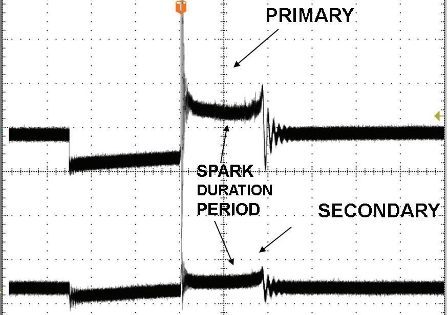
Accessing the primary or secondary side of the ignition systems on some late model vehicles is a real challenge. In addition, many COP-type coils are so heavily potted that the magnetic field is too weak when attempting to obtain a secondary ignition waveform, which presents a real challenge when using a secondary KV probe. See Fig. 1. Secondary leads are available from AESwave. com to connect to the coil and spark plug and then
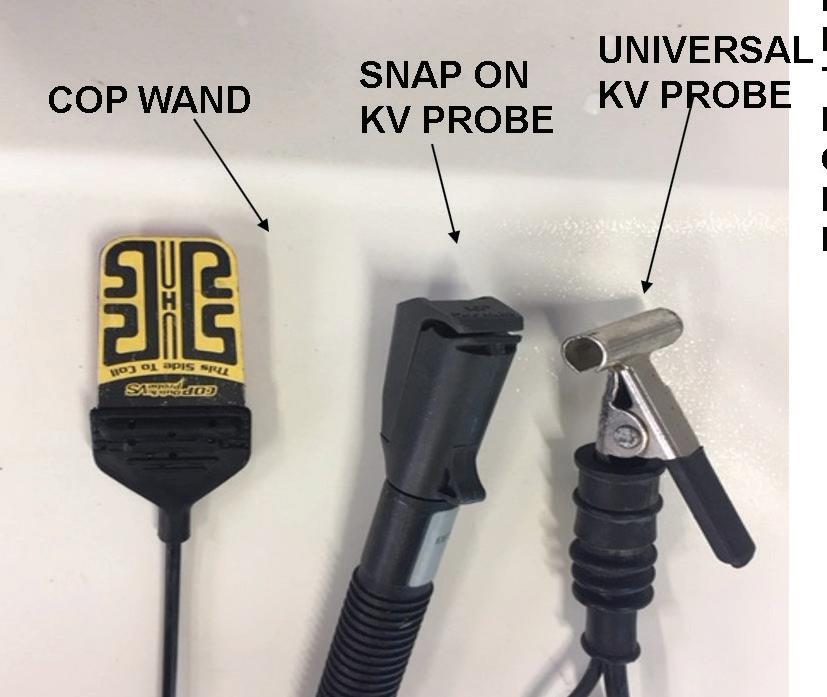
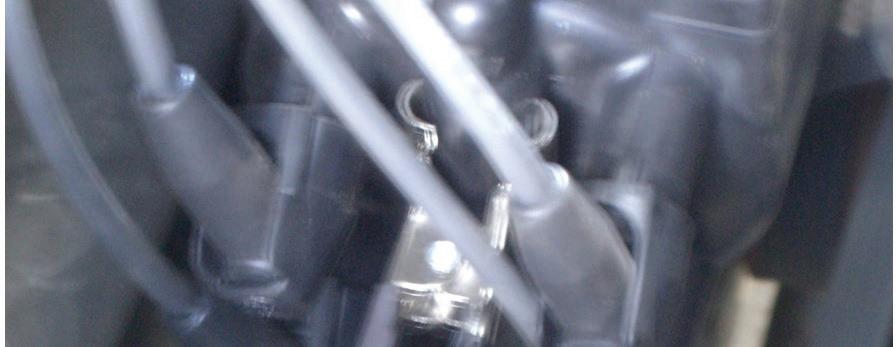

clamp around the plug wire with a KV probe. Remember the secondary firing events are negative polarity so you must use your invert function. Nevertheless, access to the primary or secondary side of the coils is available on most late model vehicles. Spark testers are usually our first choice in the event of a single cylinder misfire. All COP coils have the ability to fire a 30 KV event. There are various spark testers available, but we must understand the KV demand of these spark testers to stress a coil. See Fig. 2. Spark testers are used to stress a coil. A consistent blue spark will tell us that the coil is performing properly when using the right spark tester.
When possible, we prefer to monitor a primary or a secondary waveform using our DSO and focus initially on the spark duration period during a park no load condition followed by a light power brake condition. We will primarily focus on the spark line because it is our electronic window inside the combustion chamber. The spark line angle and duration period will literally mirror each other so it will not matter which side of the coil you access. See Fig. 3.



Access to the primary side of the coil is usually very easy on the Ford and Chrysler systems.
Let’s look at a vehicle that suffered from a light load misfire. The engine is a distributor-equipped engine. We used the universal KV probe on the coil tower. See Fig. 4. Notice the short spark duration period in Fig. 5 during a park idle no-load condition. The engine had the spark plugs recently replaced with no improvement. Notice the major increase in the spark duration period after the distributor cap and rotor and plug wires were replaced in Fig. 6. The light load misfire was gone.


Ford is so sensitive to light load lean density misfires that the PCM will multi fire the coils below 1,000 rpm. See Fig. 7.

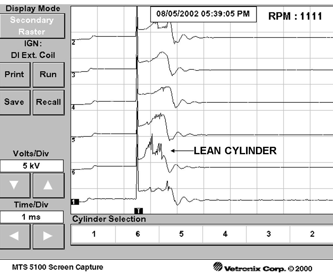
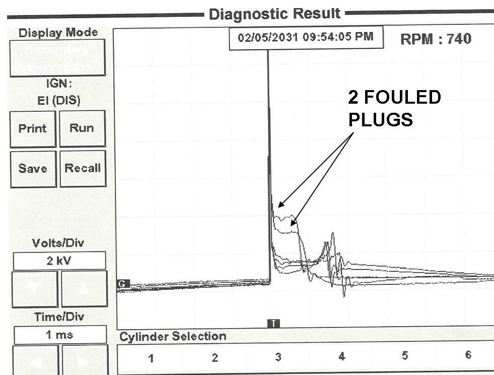
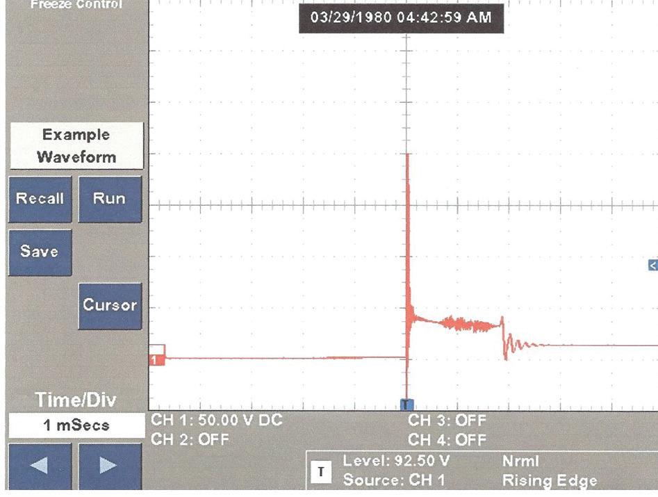
Lean density misfires are seen easily on the secondary or primary side of the coil. The Snap-on units and the Master Tech 5200 scopes allow us to raster the secondary side as seen in Fig. 8. Notice the short spark duration period from the No. 6 cylinder captured during a light power brake condition. Rich air fuel conditions can easily foul spark plugs as seen in Fig.9. Notice the high KV point and the sloping down spark lines from No. 2 cylinder. I had a tech call on a 5.3L Chevy Silverado with a misfire on No. 1 cylinder. The shop had replaced the spark plugs and the coil for the No. 1 cylinder. The COP wand was laid next to the No. 1 plug wire on this coilnear-plug system. What is the waveform telling us in Fig. 10? Notice the very low firing KV value of 4 KV and a very long spark duration period of over 3 mil -

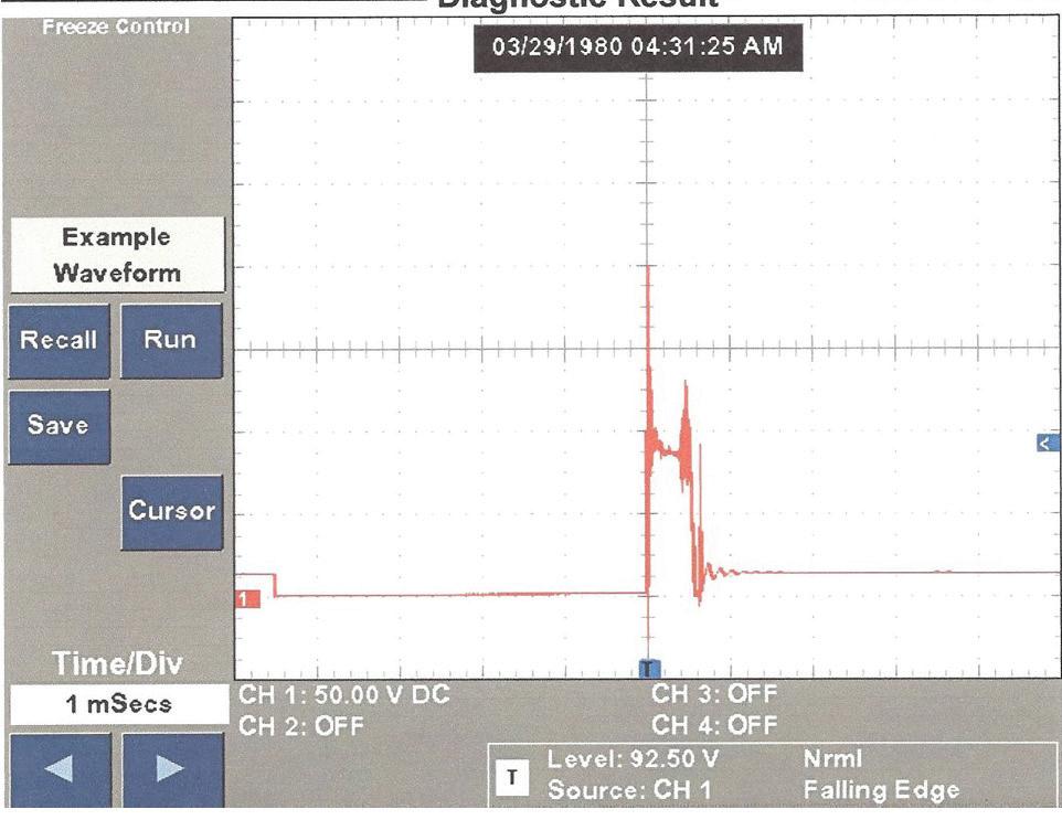
measured
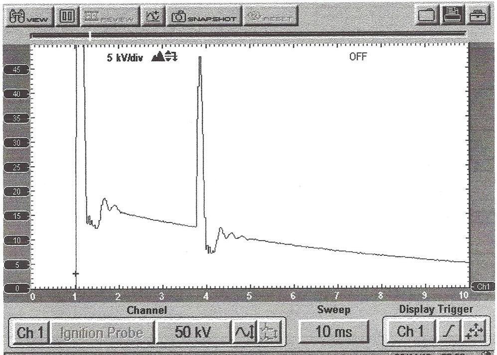
20 psi. Notice in Fig. 11 the secondary waveform after the exhaust valve was replaced showing a good firing line voltage of 10 KV and a good spark duration period of slightly over 2 milliseconds. Many times on my tech calls to other shops, the problem turns out to be something the technician overlooked. This 4.0L Ford engine exhibited a light load misfire on cylinder No. 3. All of the secondary components were replaced by the truck owner. The technician working on the truck enlisted in a tech line service and was told the valve springs were known to cause this problem. The technician replaced both valve springs on cylinder No. 3 to no avail. I simply went to the shop and scoped out cylinder No. 3. See Fig. 12 from an open in the spark plug resistor.

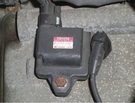
A Toyota came in with misfire under load complaint. The spark plugs were replaced by the truck owner. This is a DIS type ignition system with an external ignitor. We simply probed the primary negative terminal at the ignitor for coil pack 1/4. First notice the decal on the 1/4 coil in Fig. 13 stating that multi ground electrode spark
plugs must be used. The primary ignition waveform is shown in Fig. 14. Notice the very short spark duration period from the primary side of the coil. We removed a spark plug and found aftermarket single electrode spark plugs. We replaced all the spark plugs with OE multiground electrodes.
Now in Fig. 15 notice the good spark duration period with the misfire now gone.
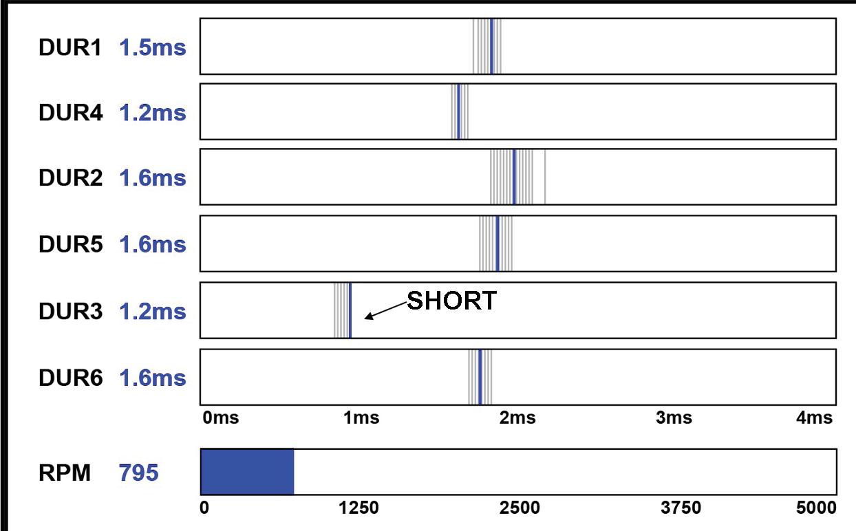


On the Chrysler systems the coils are controlled by the primary drivers inside the PCM. Chrysler now gives us scan data indicating the time of the collapsing magnetic field which is essentially the spark duration period. This is the artificial intelligence from the automotive industry and should be used for comparison purposes only. Fig. 16 indicates a shorter than normal value of the No. 1 cylinder compared to the other cylinders. The vehicle simply needed new OE spark plugs.
Since the primary drivers are inside the PCM on the Ford systems, Ford is doing what Chrysler is doing in that it times the collapsing magnetic field as shown by scan data in Fig. 17. This was captured above 1,000 rpm where the PCM reverts to a single firing event. Again, this data should be used for comparison purposes only.
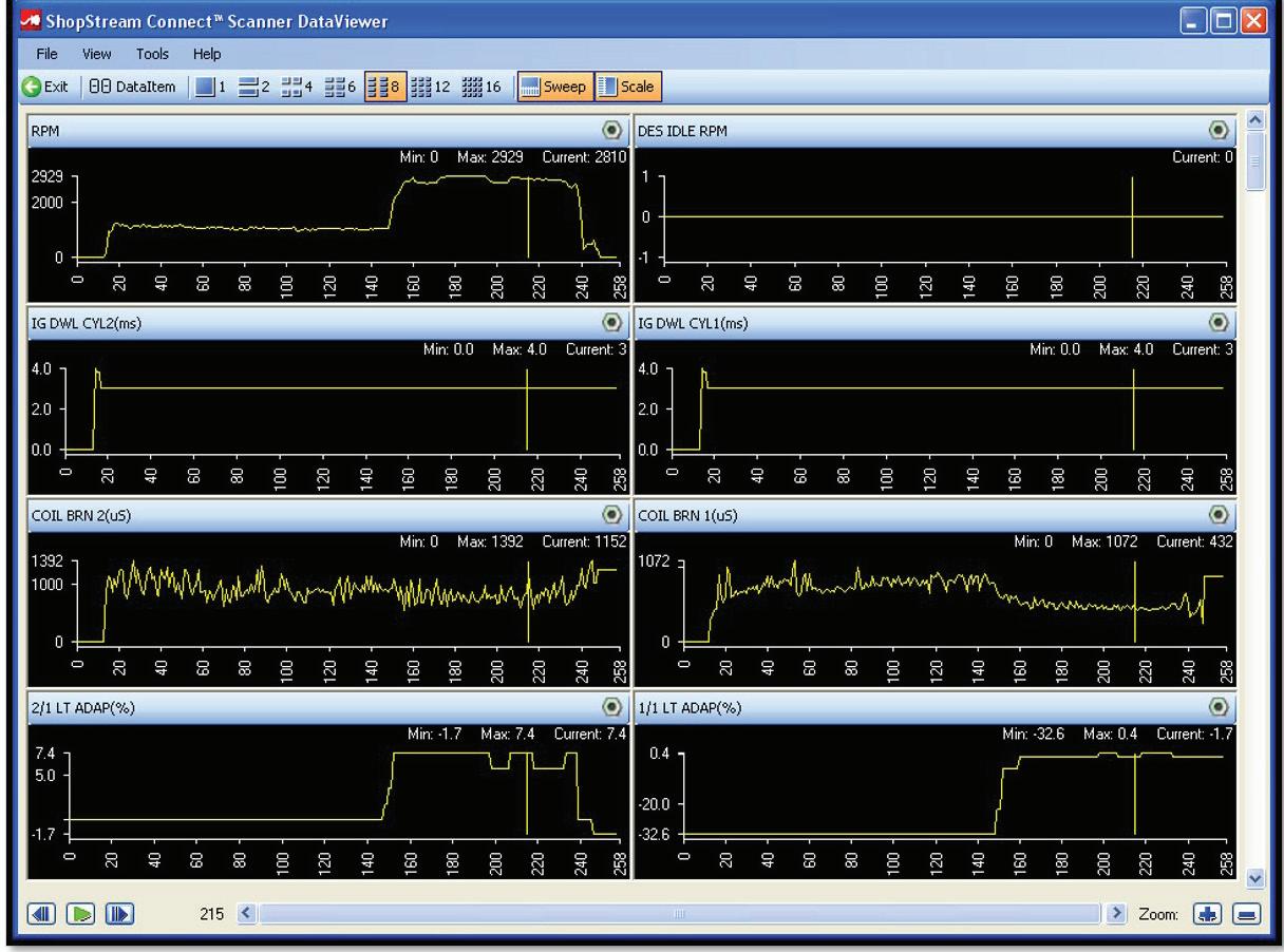
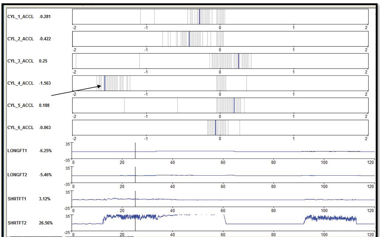
In Fig. 18 a capture was done below 1,000 rpm indicating a cylinder with a long spark line. This could be caused by a rich fuel condition or a low compression issue. Fig. 19 is from a Ford system indicating a short spark duration. This could be caused by a lean cylinder especially if this data shows up during a light power brake condition. In Fig. 20 Ford is timing the crank angle values after a firing event from the CKP sensor. Notice the acceleration PID for cylinder No. 4.
One of my favorite tests to do is a WOT clear flood cranking mode and to monitor the KV value and the spark line characteristics. Good compression values will create elevated KV demand. Notice in Fig. 21 the KV demand exceeded 14 KV with a spark duration period of over 2 milliseconds. This verifies good compression and stresses the coil for good performance. In Fig. 22 we conducted the WOT cranking test on a 4-cylinder using the bar graph function of the scope. Notice the 27 KV to 30 KV demand indicating good compression and stressing the coils.

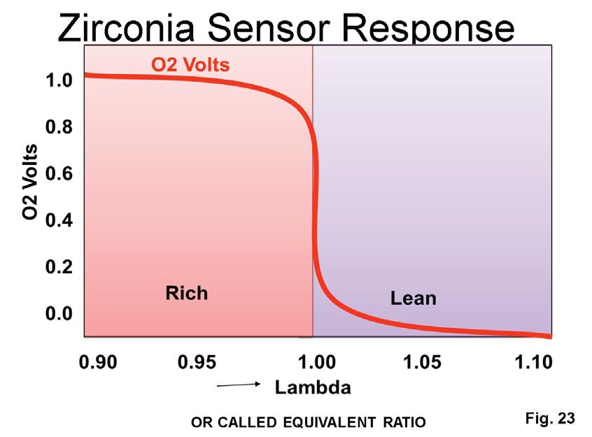

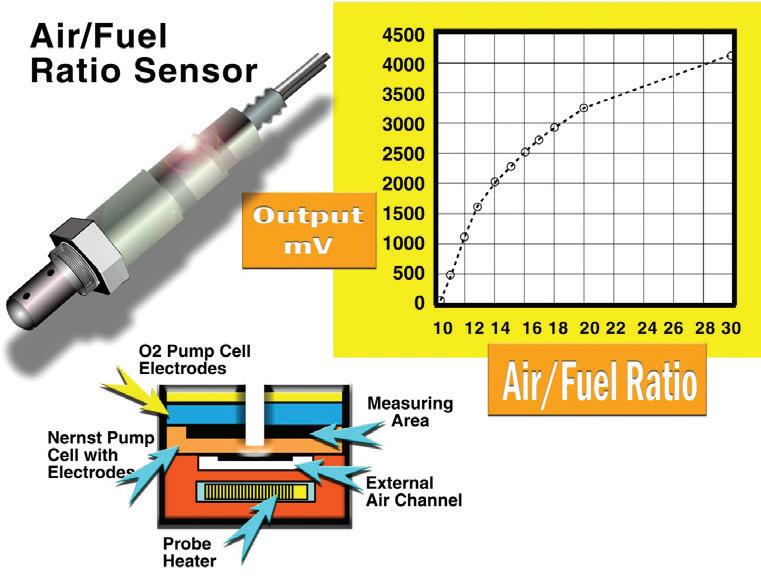
There are three types of oxygen sensors currently used by the manufacturers. The standard and most popular Zirconia oxygen sensor, the Wide Range oxygen sensor and the Titanium oxygen sensor. Fig. 23 illustrates the zero to 1 volt scale for the Zirconia sensor. You can see that 450 megavolts represents 14.7-to-1 air fuel ratio. The issue with these sensors is they cannot see full enrichment or full enleanment. But all downstream oxygen sensors are Zirconia-type sensors. Fig. 24 shows the relatively new wide range oxygen sensor. These sensors can see a full rich and full lean condition.
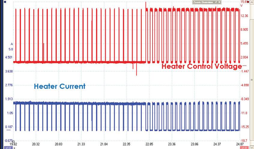
You can see that 2,200 megavolt represents a 14.7 air fuel ratio. Ford systems are also using the new wide range air fuel ratio sensor. In Fig. 25 notice that the value is displayed in a milliamps value. When the milliamps value goes positive, a lean condition exists. When the milliamps value goes negative, the exhaust condition is rich. Fig. 26 shows the heater control from a Hyundai system. You can see the heater circuit is supplied voltage from a relay and the PCM ground side controls the current flow. These heating elements are of the 40-watt standard. This allows quicker heat up and faster operation into closed loop condition. Looking at the voltage supply and the current flow value in Fig. 27 you can see that the amperage peaked at about 1.6 amps.
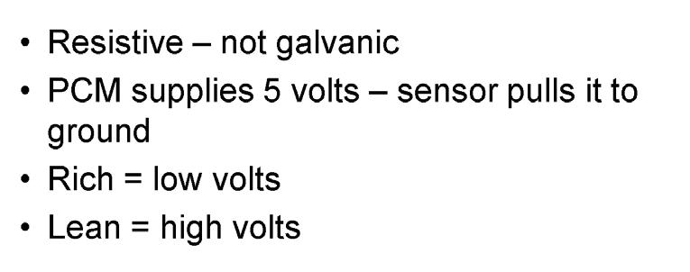
Looking at a throttle snap from a wide range oxygen sensor from a Hyundai system in Fig. 28, notice the megavolt value goes low for enrichment and goes high during enleanment. The Titania style sensors are used on some systems. See in Fig. 29 the PCM supplies 5 volts to this sensor. When the sensor is plugged in it pulls the voltage to ground. In closed loop operation when the voltage goes low, it represents a rich condition while the voltage goes high and represents a lean condition. Twoand-a-half volts represents a 14.7 fuel/air ratio.


The industry is better because of your commitment.
Bill Fulton is the author of Mitchell 1’s Advanced Engine Performance Diagnostics and Advanced Engine Diagnostics manuals. He is also the author of several lab scope and drivability manuals such as Ford, Toyota, GM and Chrysler OBD I and OBD II systems, fuel system testing, many other training manuals in addition to his own 101 Lab Scope Testing Tips. He is a certified Master Technician with over 30 years of training and R&D experience. He was rated a Top Technical Trainer and has instructed for Mitchell 1, Precision Tune, OTC, O’Reilly Auto Parts, BWD, JD Byrider, Snap-on Vetronix and Standard Ignition programs. You may have also seen Fulton in many Lightning Bolt Training videos and DVDs and read his articles in many auto service magazines. He
operates Ohio Automotive Technology,
is
This bulletin applies to 2016 BMW 330e PHEV (plug-in hybrid electric vehicle). During the ISTA test diagnosis, fault code 21E6E9 (charging interruption) may be found in the KLE convenience charging electronics module. There might not be a customer complaint related to charging, or a warning check control message display. An erroneous fault 21E6E9 may be stored in the KLE after completion of an air conditioning charging session. Evaluate the EME (electrical machine electronics) and KLE fault memories. If there are no other fault codes stored related to the charging system, ignore KLE fault code 21E6E9 and delete it.

The cause of the condition may be due to the inside diameter of the front strut jounce bumper rubbing against the piston rod of the strut, creating a slip-stick condition. Pull the dust boot assembly out of the strut mount jounce cup. Slide the bumper down to expose the top of the piston rod. Apply dielectric silicone grease (GM P/N 12345579) around the circumference of the piston rod only in the exposed area (1 inch from the top of the piston rod, measured from the bottom of the mount cup). Raise the bumper assembly up to the mount cup. Rotate the bumper assembly on the piston rod to ensure grease is distributed around the rod. Re-seat the dust tube/jounce bumper assembly into the mount cup.

Some owners of 2008-2014 Buick Enclave vehicles may comment about a squawk, creak or “itch” type noise coming from the front suspension that may be more noticeable in cold temperatures. The noise will most likely be heard during small to medium suspension travel.
Some 2017 Ford C-Max, Fusion Hybrid and Fusion Energi vehicles may exhibit an illuminated MIL with DTC P0071 stored in the PCM. This DTC can be set after the vehicle is stored in a warm location for several hours and then driven on a cold day. Under these conditions the PCM may see a temperature sensor concern when it first compares the ambient air temperature (AAT) sensor to other engine temperature sensors and set the DTC. Reprogram the PCM to the latest calibration using IDS release 104.04 or higher.

Owners of 2015-2016 Chevy Colorado or GMC Canyon vehicles may state that the MIL for ABS/ESC is on. The Low Brake Fluid lamp may be on (even though the master cylinder fluid level is full) or a Service Trailer Brake message is displayed. DTCs C0035, C0040, C0045, C0050, C0055, C0267, U0121, U0415 or U0420 may be stored. Inspect the EBCM connector for water intrusion or terminal corrosion. If either is found, replace the EBCM and replace the affected terminals. Remove the tape from the conduit leading to G400 between the main harness and the ground lug. If no water intrusion is found in the connector, remove the tape from the G400 conduit and continue with diagnostics.
