INTEGRATEDPROJECTDESIGNSTUDIO BOSTON,MASSACHUSETTS
A0-00COVERSHEET/TABLEOFCONTENTS
A0-01REFERENCE
A0-02SITEPLANREGIONAL
A0-03SITEPLAN
A0-04CODEREQUIREMENTS
A0-05CODEREQUIREMENTS
A0-06CODEREQUIREMENTS
A1-01FIRSTFLOORPLAN
A1-02SECONDFLOORPLAN
A1-03THIRDFLOORPLAN
A1-04FOURTHFLOORPLAN
A1-05FIFTHFLOORPLAN
A1-06SIXTHFLOORPLAN
A1-07SEVENTHFLOORPLAN
A1-08ROOFPLAN
A2-01BUILDINGELEVATIONS
A2-03BUILDINGSECTIONS
A3-01BUILDINGENVELOPE
A3-02BUILDINGENVELOPE
A3-03BUILDINGENVELOPE
S0-01STRUCTURALNARRATIVE
S1-00FOUNDATIONPLAN
S1-01FIRSTFLOORSTRUCTUREPLAN
S1-02SECONDFLOORSTRUCTUREPLAN
S1-03THIRDFLOORSTRUCTUREPLAN
S1-04FOURTHFLOORSTRUCTUREPLAN
S1-05FIFTHFLOORSTRUCTUREPLAN
S1-06SIXTHFLOORSTRUCTUREPLAN
S1-07SEVENTHFLOORSTRUCTUREPLAN
S1-08ROOFSTRUCTUREPLAN
S2-01 STRUCTUREAXON
S2-02STRUCTUREAXON
S2-03 STRUCTUREAXON
M0-01MECHANICALSYSTEMSNARRATIVE
M1-01 MECHANICALPLAN1,SYSTEM_2,3AIR
M1-02AMECHANICALPLAN2A,SYSTEM_1RADIANT
M1-02BMECHANICALPLAN2B,SYSTEM_2,3AIR
M1-03AMECHANICALPLAN3A,SYSTEM_1RADIANT
M1-03BMECHANICALPLAN3B,SYSTEM_2,3AIR
M1-04AMECHANICALPLAN4A,SYSTEM_1RADIANT
M1-04B MECHANICALPLAN4B,SYSTEM_2,3AIR
M1-05AMECHANICALPLAN5A,SYSTEM_1RADIANT
M1-05BMECHANICALPLAN5B,SYSTEM_2,3AIR
M1-06AMECHANICALPLAN6A,SYSTEM_1RADIANT
M1-06B MECHANICALPLAN6B,SYSTEM_2,3AIR
M1-07AMECHANICALPLAN7A,SYSTEM_1RADIANT
M1-07BMECHANICALPLAN7B,SYSTEM_2,3AIR
M1-08AMECHANICALROOFPLAN,SYSTEM_1RADIANT
M1-08B MECHANICALROOFPLAN,SYSTEM_2,3AIR
M2-01 MECHANICALSYSTEMSAXON
M2-02 MECHANICALSYSTEMSAXON
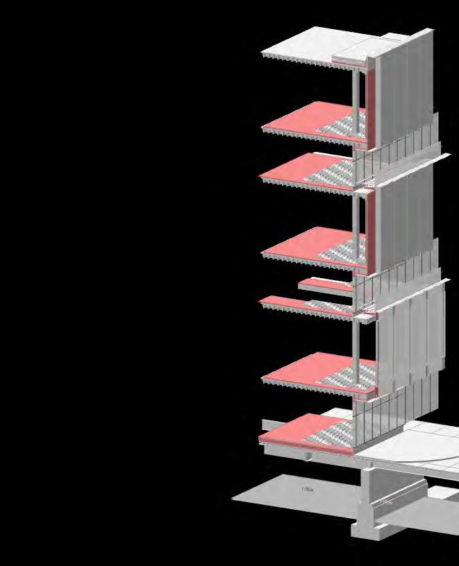
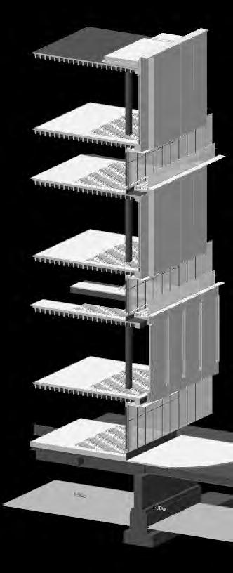
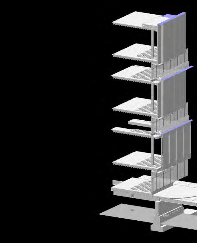
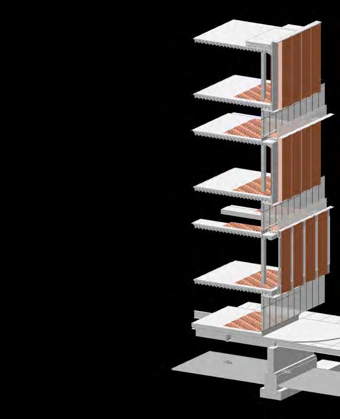
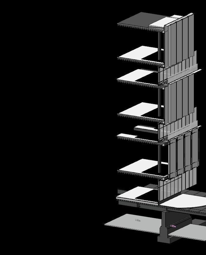
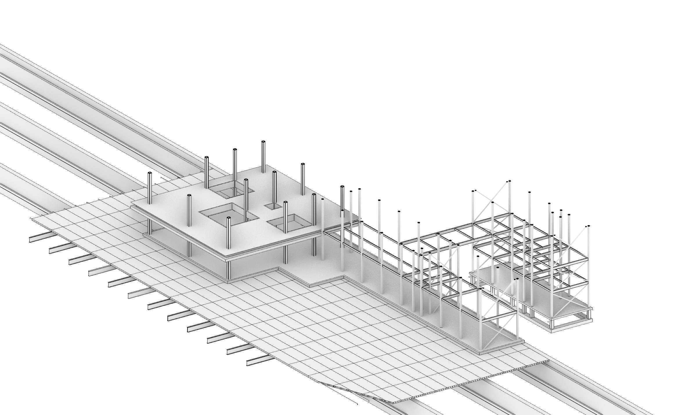
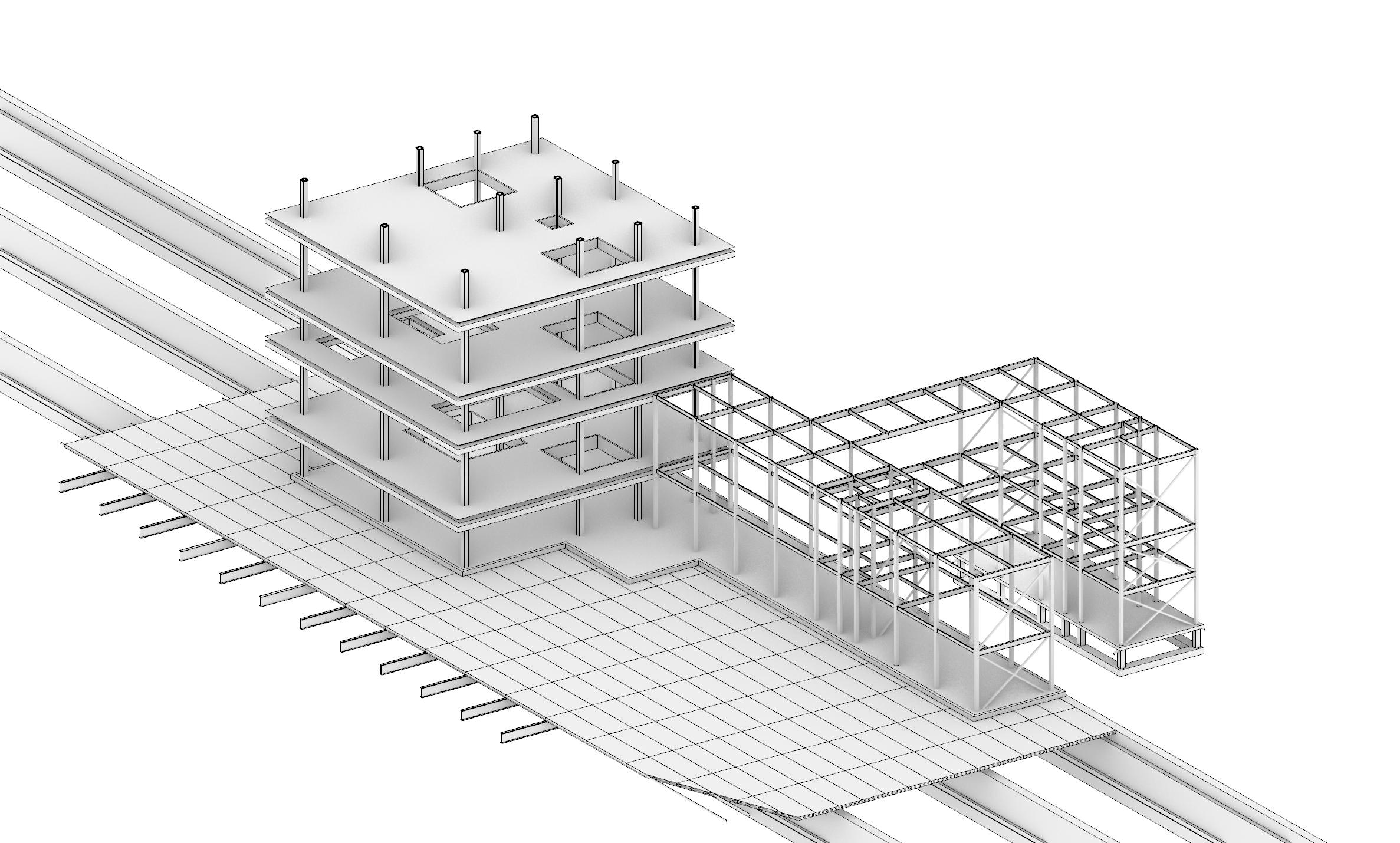
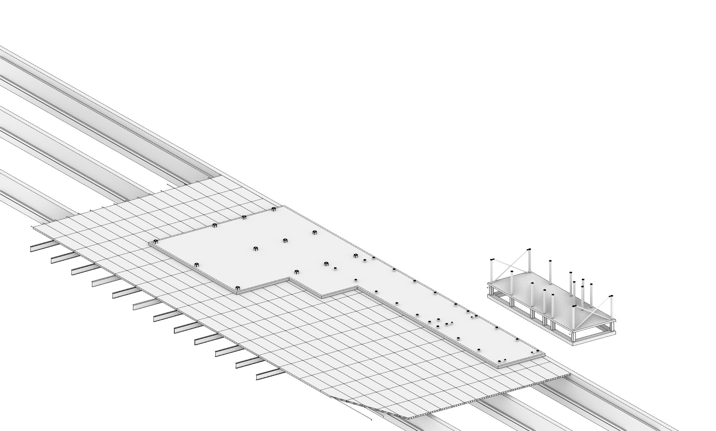
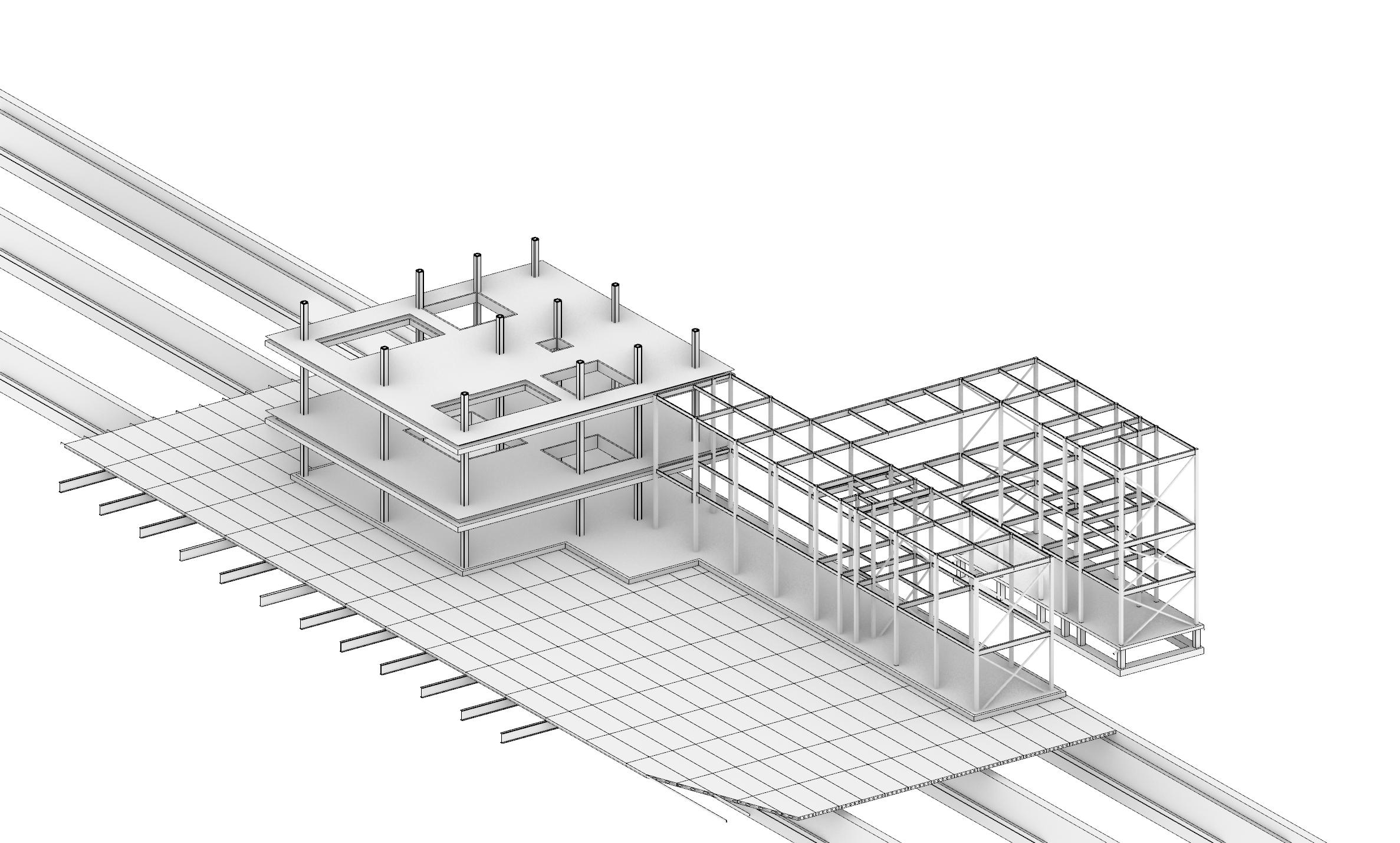
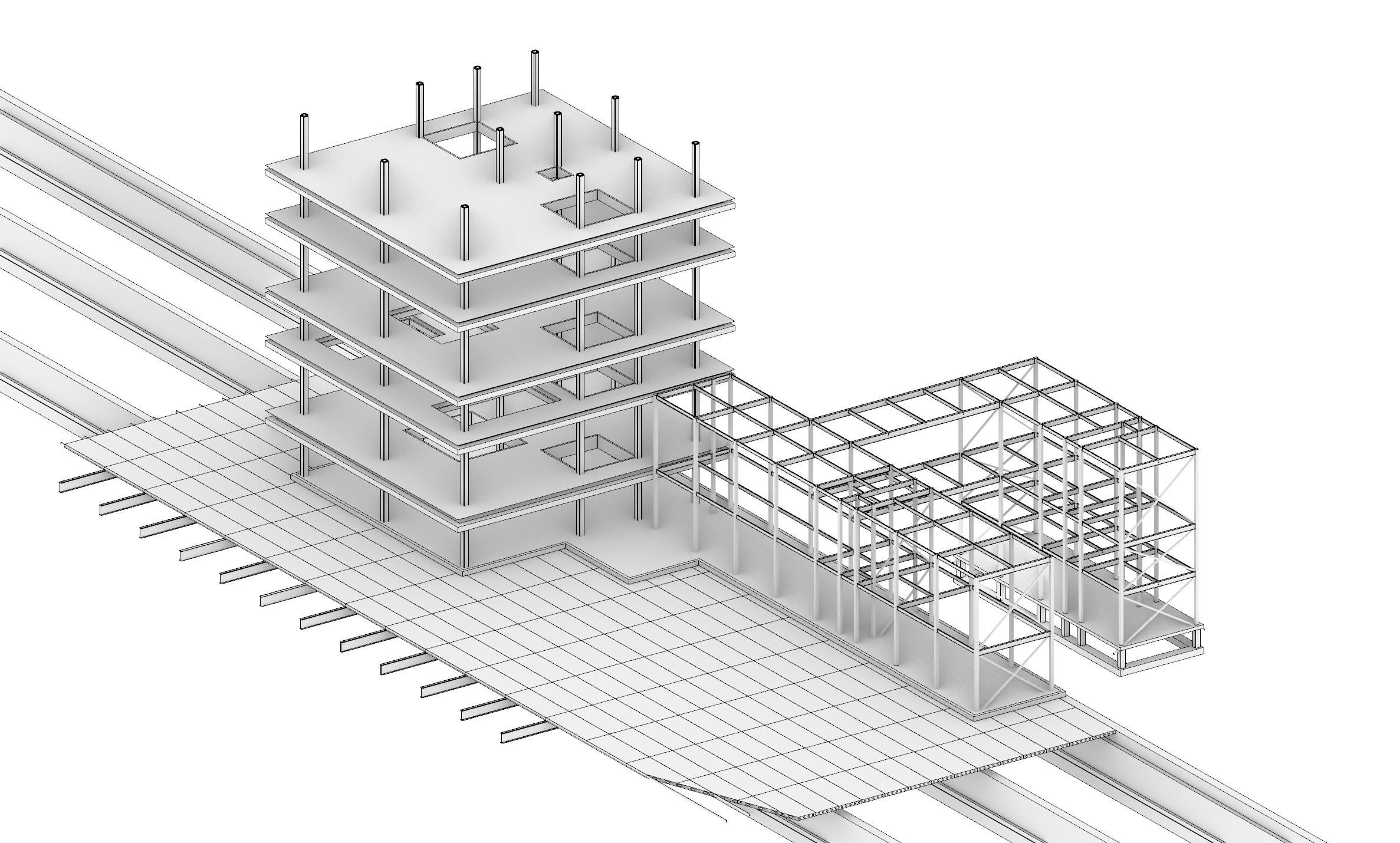
Structurally, a total of three services were required for this project. One due to the complexity of the site, and two separate systems designed for the distinct conditions of the project’s form.
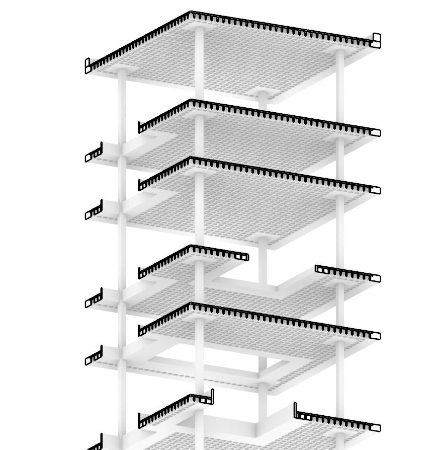
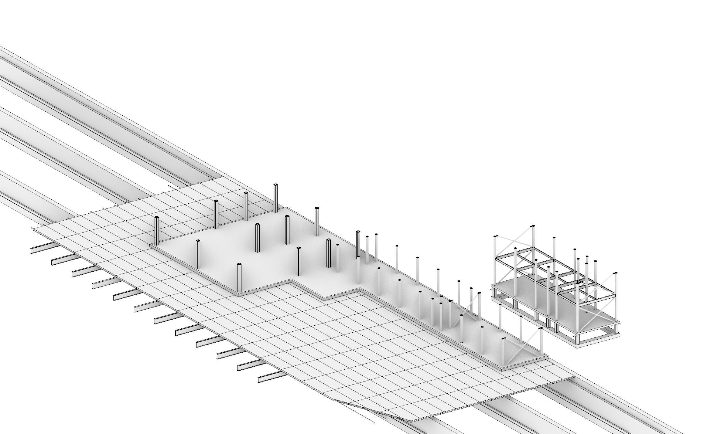
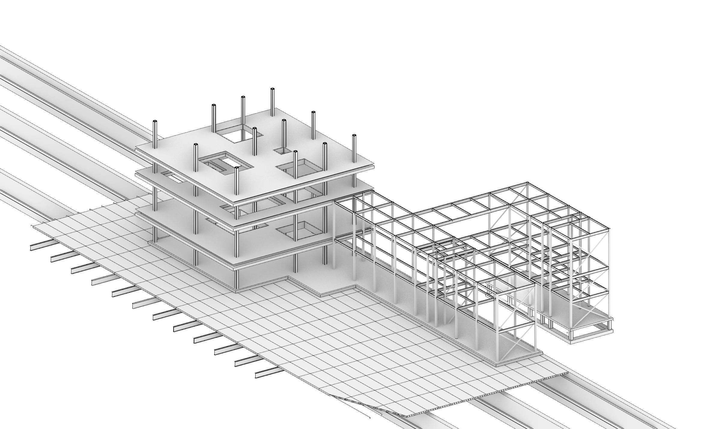
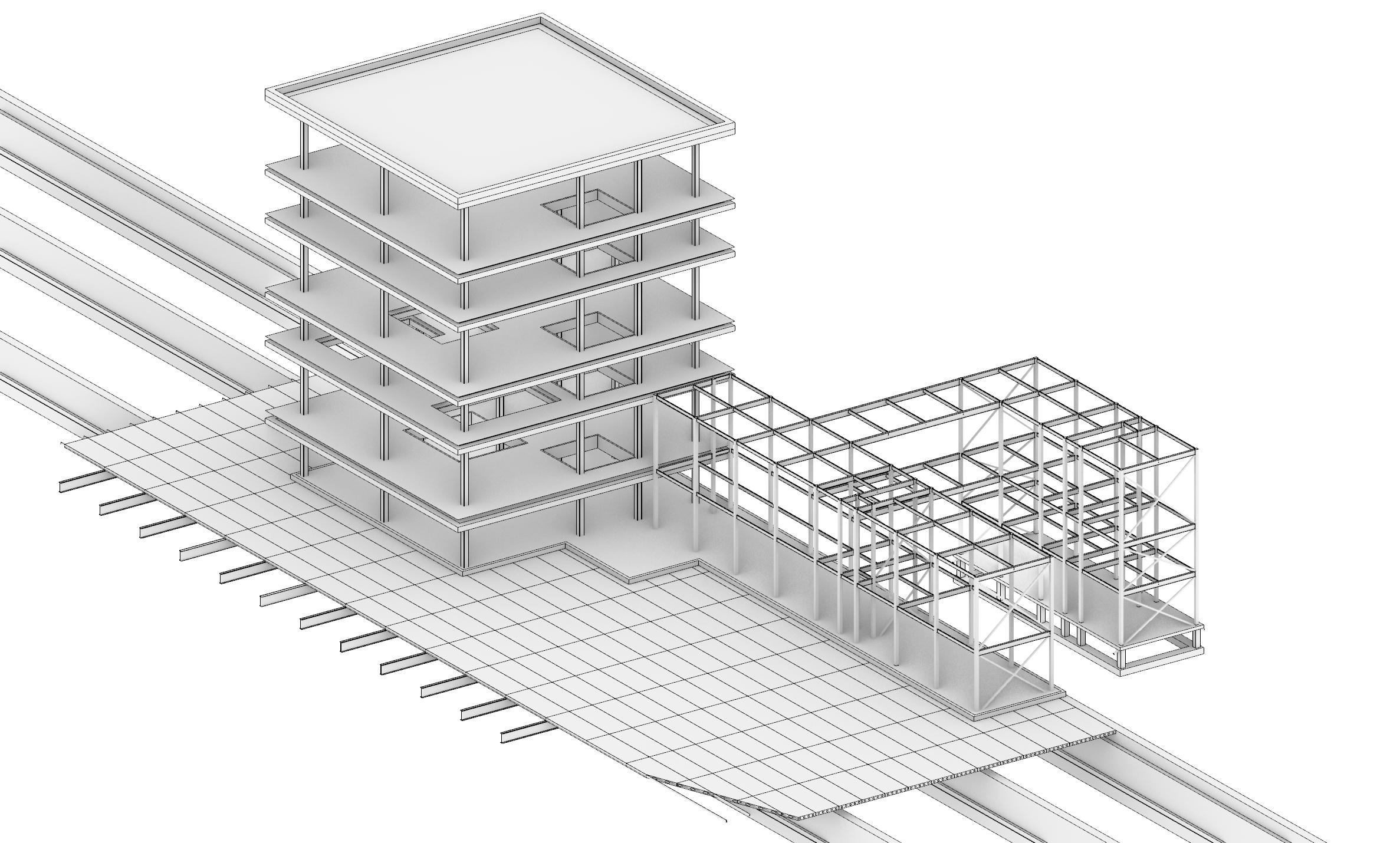
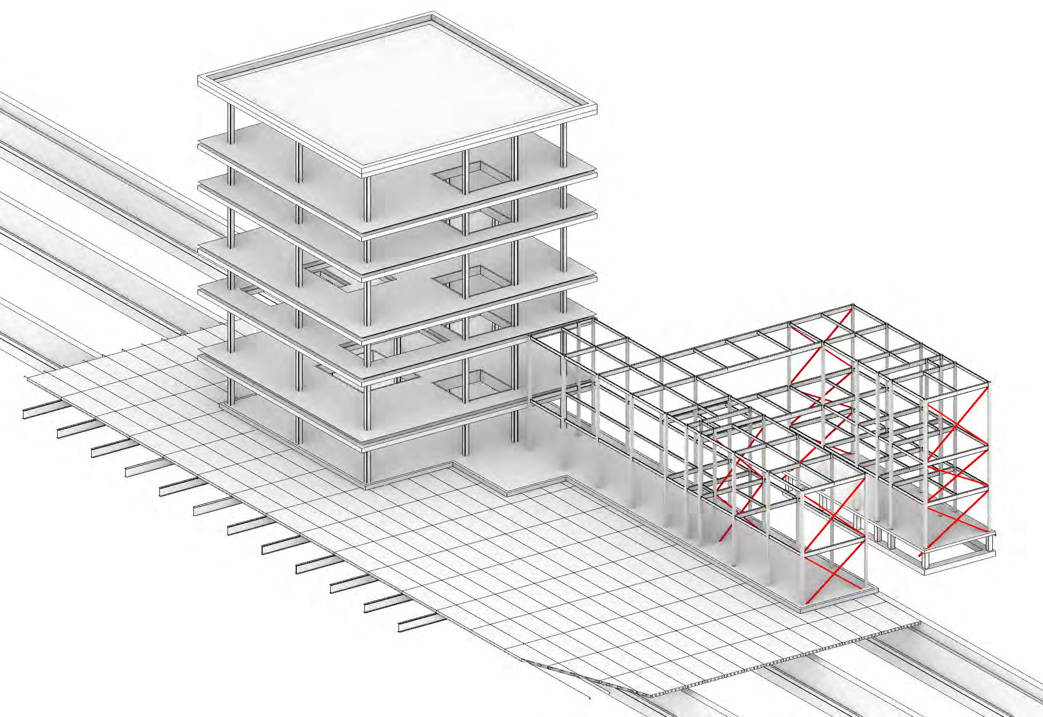
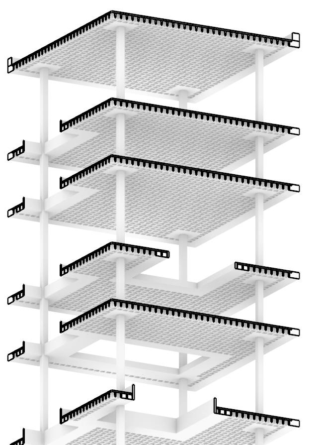
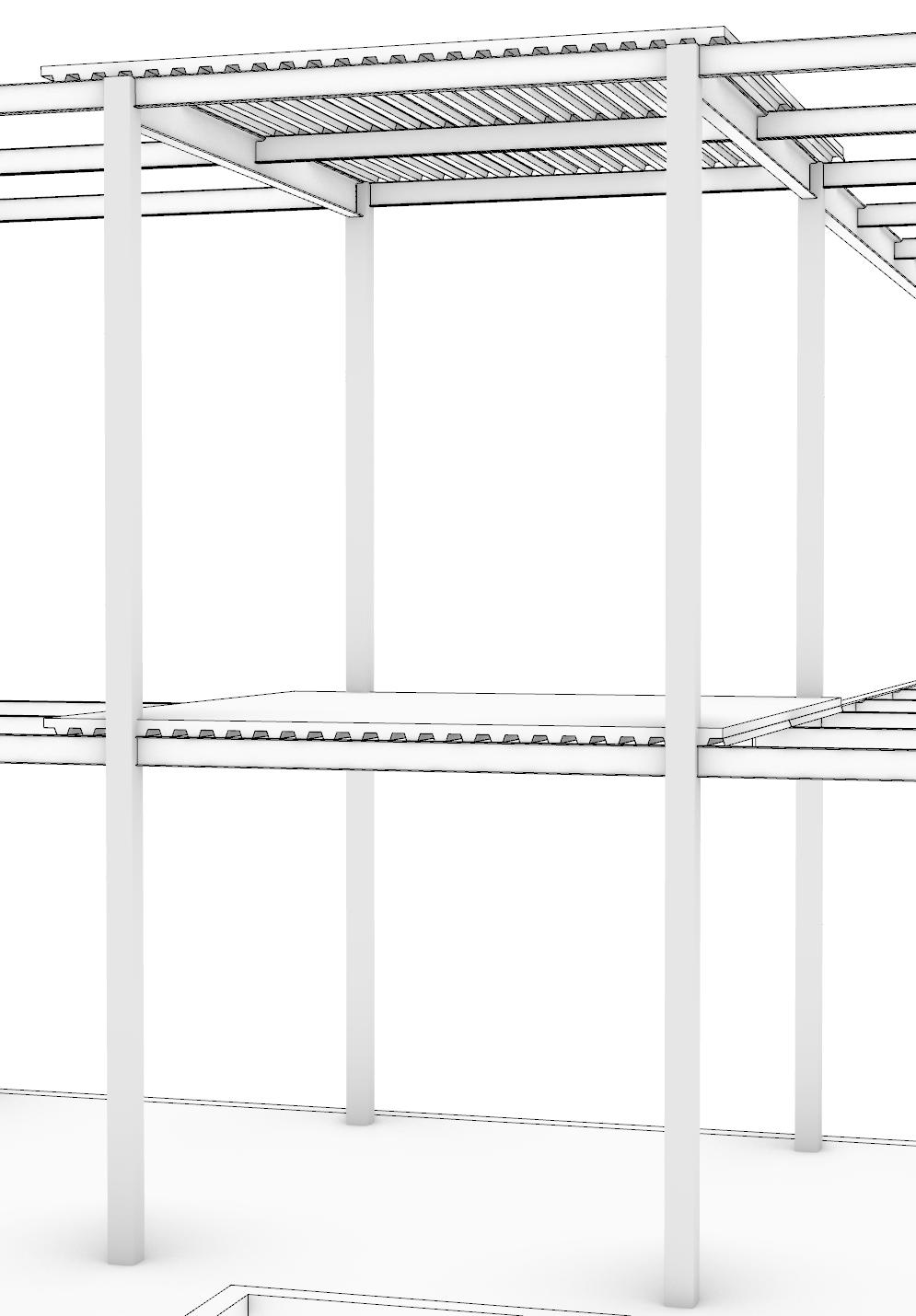
Of the systems within the building, there is a cast in place, post-tensioned concrete waffle slab system supported by a grid of columns and shear walls around the axial circulation core, and then a standard steel framing system with concrete slabs and HSS columns. The compact, repeatable organization of the building’s plan and its multitude of large spans, and large opening conditions, warrants the utilization of a waffle slab. Waffle slabs perform well with light to average loading, and large spans. A benefit of the waffle slab is its aesthetic quality on the interior. This expression of a grid reflects the building’s composition, both on the facade and organizationally. An issue with the waffle slab is construction and cost. Formwork tends to be the most expensive part of cast in place concrete construction, and this cannot be greatly mitigated unless the clean aesthetic of the exposed waffle is compromised (ie. considering a similar system like holedeck to reduce the amount of concrete used, as well as the cost of formwork). One solution was to make the system Post Tensioned, which effectively reduces the amount of concrete being used by casting the concrete in manner such that tension can be applied to the slabs internally after it is done curing, increasing its allowable spans and relative load capacity. Applying the steel system to the longitudinal portion of the building was a simple solution to connect back to the steel that was being used to support the whole project over the Massachusetts Turnpike.
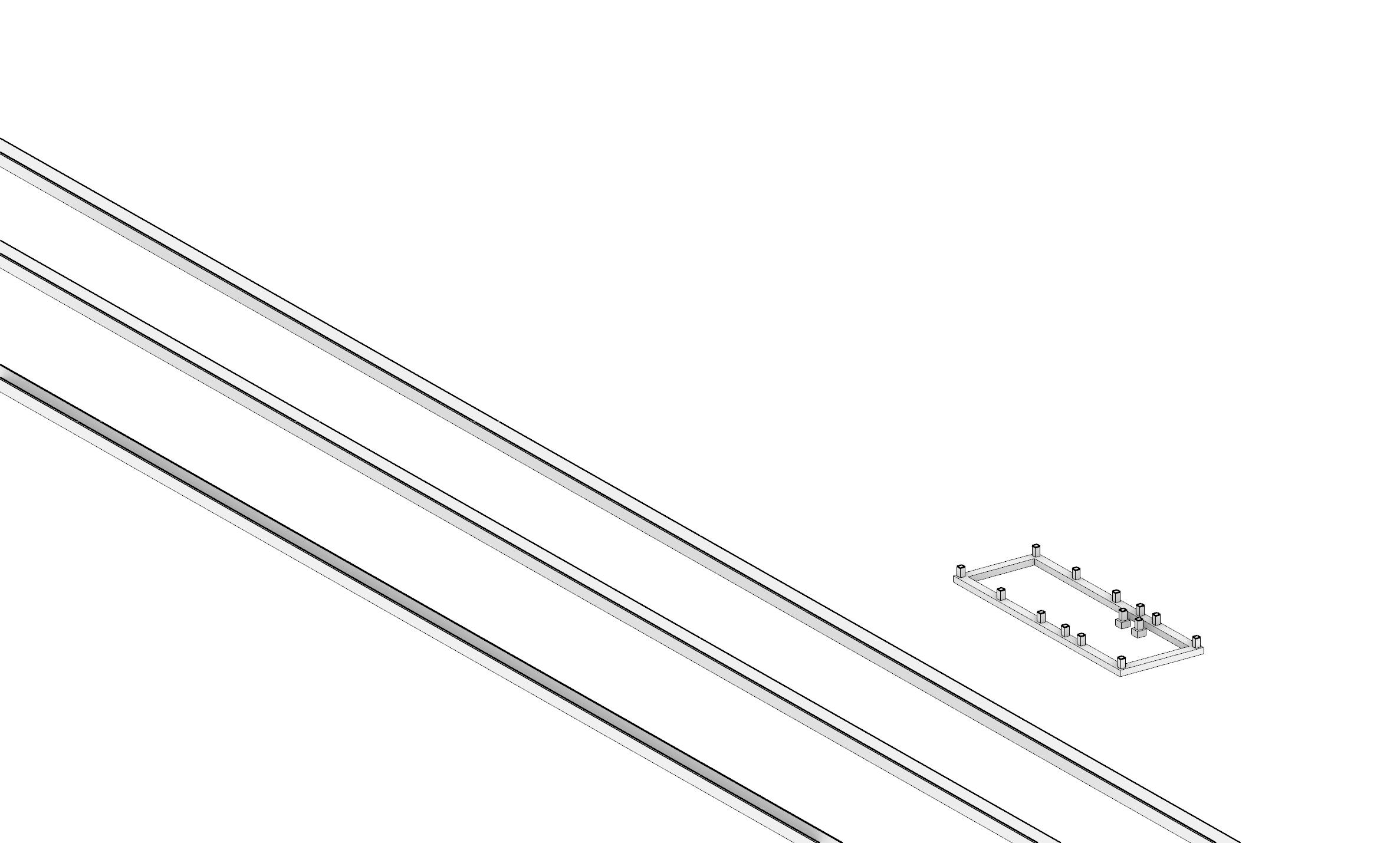
With that, the structural system below the site and above Interstate - 90 is all steel. This posed a problem for the heavy column loads coming from the cast in place waffle slab which is where the third service comes in: To account for the large loads between the building’s occupied grade and the busy thoroughfare below, a series of 4’x2’ laterally braced precast concrete beams were introduced.
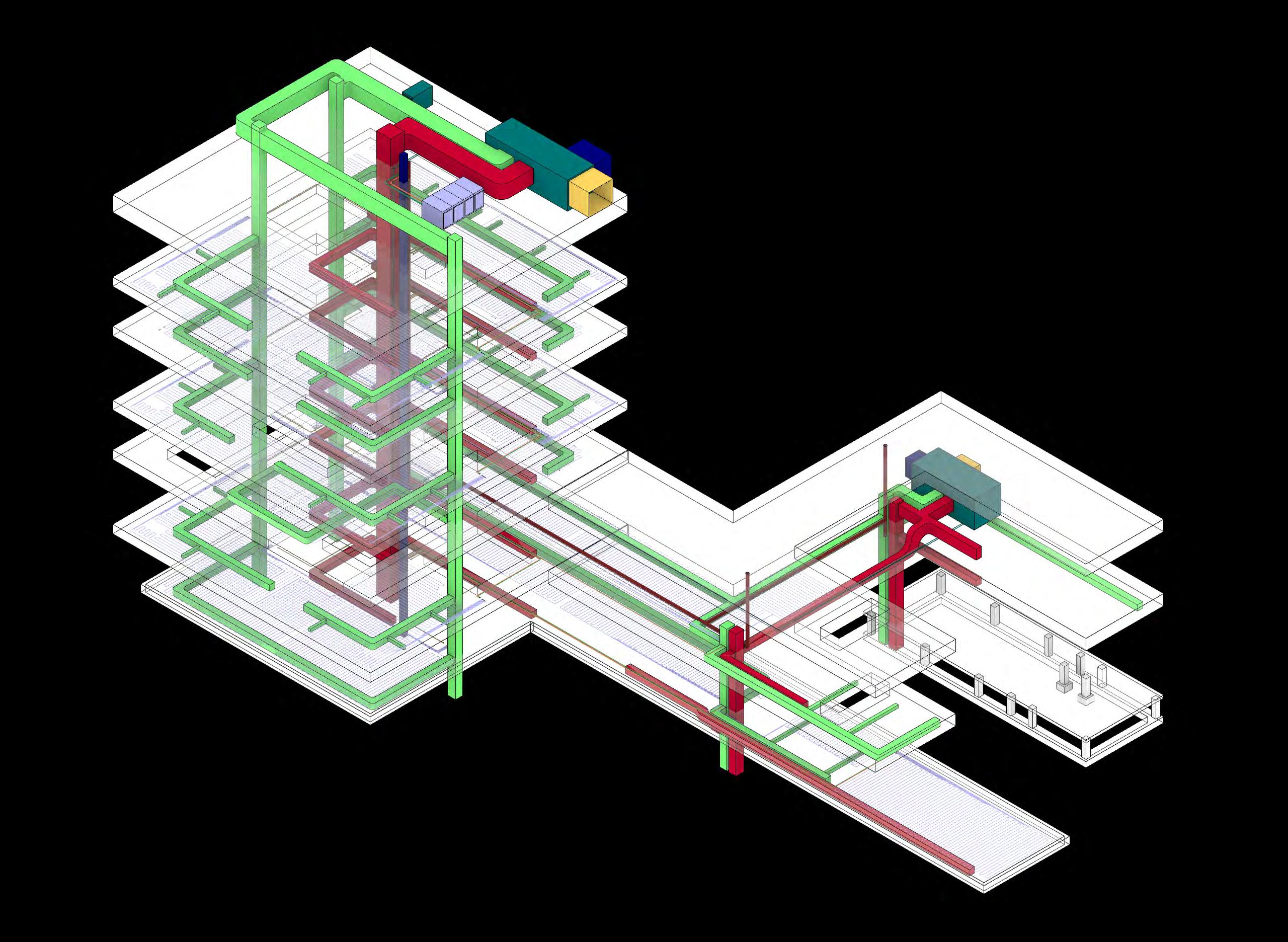
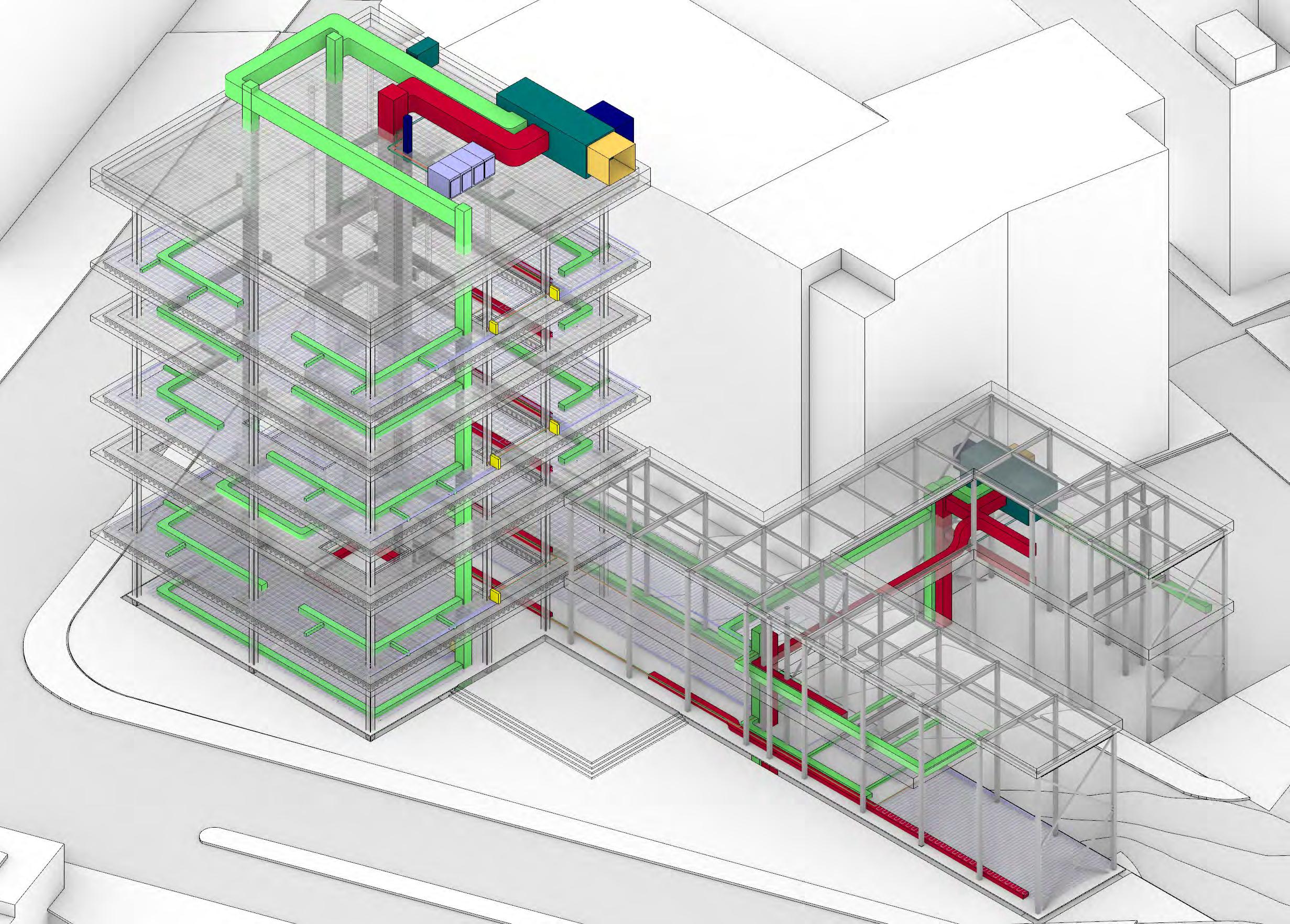
Because of the site’s lack of available land, using geothermal as a source was unrealistic. The building therefore employs Air Source Heat Pumps (ASHP) as a source, and because of the overall proximity to typical urban pollutants at the ground level, they are to be located on the roof. For the building’s climate control, a radiant heating and cooling system is designed to handle the majority of the load, while a centralized Energy Recovery Ventilator (ERV) is used for the ventilaiton and humidity control of the majority of the building. The needs of the building’s program require a suplemental Air Handling Unit (AHU) to help serve the spaces that require more thermal control as well as those that have a higher variance in occupancy. These spaces mainly include the exhibitions and experience centers.
The building uses a technical floor system to hide the duct work and maintain the exposed structural system. The raised floor is where the radiant coils are placed. Together, the AHU and ERV handle the ventilation and humidity control, while the radiant system handles the majority of heating and cooling.
4