
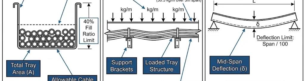

Cable tray size calculation determines the correct tray width, depth, and load class to safely route and support electrical cables. The process is governed by three simultaneous constraints under IEC 61537: fill ratio, distributed load capacity, and mid-span deflection limit. Get any one of these wrong and the installation either fails thermally, structurally, or at inspection.
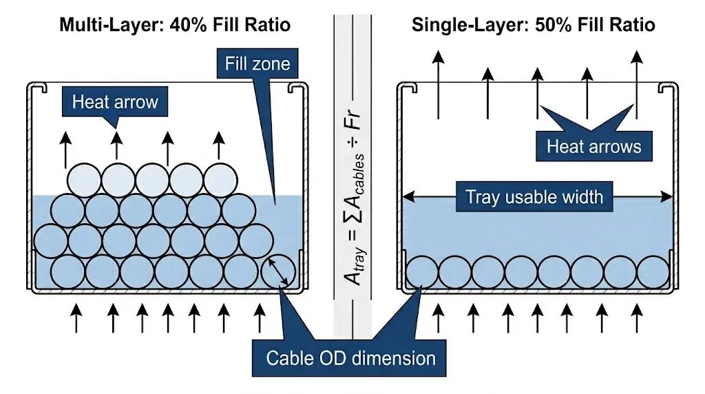
The foundational formula is straightforward: required tray cross-sectional area equals the sum of all cable cross-sectional areas divided by the permitted fill ratio. IEC 61537 — the international standard for cable tray systems and cable ladder systems — sets the fill ratio at 0.40 (40%) for multi-layer arrangements and 0.50 (50%) for confirmed single-layer arrangements. When in doubt, always default to 0.40.
The Three Input Variables
Every cable tray size calculation starts with three inputs:
1 Cable inventory — the outer diameter (OD) and weight per metre of every cable in the run
2 Tray span — the centre-to-centre distance between support brackets (typically 1,500–3,000 mm)
3 Load class — the IEC 61537 structural rating required to carry the total cable bundle weight
These three variables are interdependent. A wider tray reduces fill ratio; a shorter span permits a lower load class; a higher load class allows a longer span. Optimising all three simultaneously is what separates a wellengineered cable management system from an over-specified one.
Fill Ratio Rule: 40% vs. 50%
The fill ratio limit exists because cables in a single layer dissipate heat laterally, while stacked cables trap heat in the bundle core. The lower 40% limit for multi-layer arrangements compensates for this reduced heat dissipation and preserves ampacity derating margins. Using 50% when cables are actually stacked is the single most common engineering error in cable tray sizing — and it is caught at commissioning, not during design.
Step 1 — Build Your Cable Inventory
Accurate cable tray size calculation is impossible without a complete cable schedule. Before touching any formula, collect four parameters for every cable routed in the tray segment being sized.
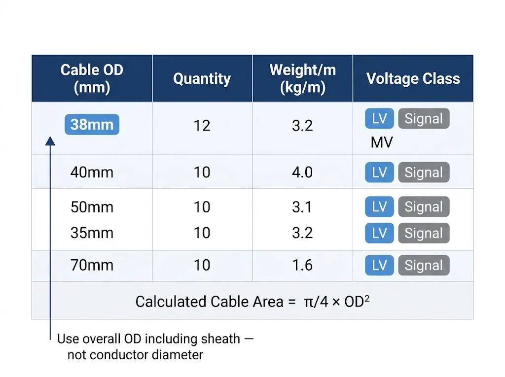
In a 2023 manufacturing plant expansion in Ningbo (14 process units, over 8,500 metres of cable routing), the cable schedule included 22 power cables from 16 mm² to 240 mm² cross-section and 31 instrumentation cables with ODs between 8 mm and 22 mm. When the initial tray sizing was performed using conductor cross-section areas instead of cable ODs, the calculated fill was understated by 34% — a difference that only surfaced during the cable-pulling stage when installers discovered the tray was at 91% actual fill.


Cable OD (mm)
Manufacturer datasheet — overall dimensions Using conductor cross-section area instead
Cable quantity Approved cable schedule Forgetting spare cables allocated but not yet run
Weight per metre (kg/m)
Manufacturer datasheet Ignoring armour and sheath weight contribution
Voltage class (LV / MV / Signal) Project electrical specification Mixing voltage classes without segregation check
Why Voltage Class Drives Segregation (and Multiplies Tray Count)
Power cables and instrumentation or signal cables generally require physical separation — via separate trays or a grounded metallic divider — to prevent electromagnetic interference with signal circuits. This requirement multiplies tray count before the fill ratio calculation even begins. On a medium-sized industrial plant, segregation requirements typically add 30–40% to the total cable tray quantity specified at tender stage.
Step 2 — Calculate Required Cross-Sectional Area
With the cable inventory complete, calculate the cross-sectional area each cable occupies in the tray. Use the circular area formula based on cable OD — not conductor cross-section.
The Fill Ratio Formula Explained
A_tray = Σ(π/4 × OD²) ÷ Fr
Where:
A_tray = minimum required tray cross-sectional area (mm²) OD = outside diameter of each cable (mm) Fr = fill ratio (0.40 for multi-layer, 0.50 for single-layer)
Worked Example:
12-Cable Power Run
Twelve cables, each with OD = 38 mm:
Individual cable area: π/4 × 38² = 1,134 mm²
Total cable area: 12 × 1,134 = 13,608 mm²
Required tray area at 40% fill: 13,608 ÷ 0.40 = 34,020 mm²
A standard 400 mm wide × 100 mm deep ladder tray provides a usable area of approximately 38,000 mm² (after deducting 12.5 mm per side rail flange). This passes the fill ratio check with a 12% spare capacity margin — sufficient for one or two future cable additions without tray replacement.
Single-Layer vs. Multi-Layer: Which Fill Ratio Applies?
Apply 0.50 only when you can confirm that all cables in the tray will be installed in a single layer for the entire run, including at bends, transitions, and vertical risers. If any section of the run causes stacking — even at a 90° elbow — the entire run reverts to the 0.40 limit under IEC 61537.
Step 3 — Select Tray Width, Depth, and Load Class
With the required cross-sectional area calculated, map it to a standard tray size. Standard widths in IEC 61537 follow the series: 100, 150, 200, 300, 400, 500, 600, 900 mm. Standard depths are 50, 75, 100, and 150 mm. Always round up to the next standard size — never down.
Usable Area vs. Gross Area: The Flange Deduction
Tray manufacturers quote nominal width — the external dimension. Usable interior width is typically nominal width minus 25 mm (12.5 mm per side rail flange). A 400 mm nominal tray provides 375 mm usable width. At 100 mm depth, usable area = 375 × 100 = 37,500 mm². Always use usable area, not nominal area, in fill ratio calculations.
Matching Load Class to Cable Weight per Metre
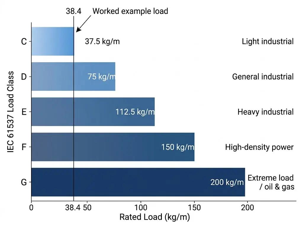
Sum the weight per metre of all cables in the tray (from the cable inventory). Select the IEC 61537 load class whose rated distributed load exceeds this total. IEC 61537
Class C
Class
Class
Class
Class G
kg/m Light commercial, instrument trays
General industrial
Heavy industrial, data centres
High-density power distribution
Petrochemical, oil & gas platforms
For the 12-cable worked example above: 12 cables × 3.2 kg/m each = 38.4 kg/m total. Class D (75 kg/m) provides a 95% margin — appropriate for a power distribution run where cables may be added over the facility’s lifetime.
The 20% Spare Capacity Rule
NEMA VE 1 recommends maintaining a minimum 20% spare cross-sectional area after filling. This accommodates future cable additions without requiring tray replacement or re-routing. In practice, selecting the next standard size up from the calculated minimum typically satisfies this rule automatically
Step 4 — Verify Fittings, Bends, and Span Limits
Passing the fill ratio and load class checks for a straight run is necessary but not sufficient. Three additional checks govern the complete installation: bend radius at fittings, reducer bottlenecks, and mid-span deflection.
Bend Radius Requirements for Power Cables
At every 90° elbow, horizontal bend, or vertical riser, each cable must maintain its minimum bend radius — typically 6× to 10× the cable OD for power cables, as specified by the cable manufacturer. For 38 mm OD cables, minimum bend radius is approximately 228–380 mm. Cable tray elbows should use a centreline radius of at least 300 mm for this cable group, and the elbow width must be checked independently using the same fill ratio formula applied to the elbow’s interior cross-section.
Reducer Bottleneck Principle
Where tray width reduces — for example, from a 600 mm main highway to a 300 mm branch run — the narrower tray governs the fill ratio for the entire downstream run. Recalculate fill ratio at the reducer using the smaller usable area. The cable tray fittings at transition points are often the most undersized element in cable routing systems.
Span and Deflection: The span/100 Hard Limit
Step up to a higher load class (heavier side rails, lower deflection), or Reduce support spacing (move brackets closer together)
Do not increase tray width to solve a deflection problem — width does not affect structural stiffness.
Tray Type vs. Sizing: Which Structure Fits Your Load?
Fill ratio calculation applies equally to all tray types, but each tray type has structural and environmental characteristics that affect which load class is achievable and how heat dissipation behaves.
Figure 4. Cable tray type selection matrix: ladder trays support the highest load classes (up to 200 kg/m) and optimal heat dissipation for power cables; perforated and solid-bottom trays suit mixed LV and instrumentation layouts where mechanical protection is prioritized.
In a Shenzhen Tier-III data centre project completed in 2024, ladder cable tray at 600 mm width was selected for all primary power distribution runs — achieving Class F load rating with full natural ventilation and a measured fill ratio of 43% after installation. Three parallel perforated cable tray runs at 300 mm width handled segregated instrumentation and structured cabling alongside, each sized at 38% fill. The result was a cable management system that passed thermal verification with zero derating factors applied to any power circuit.
Five Sizing Errors That Cause Expensive Rework
In cable management projects across industrial plants, data centres, and commercial buildings, the same five errors recur. Each one is preventable at the design stage and expensive to fix after installation.
Error 1 — Using conductor area instead of cable OD. Conductor cross-section (mm²) measures only the copper or aluminium core. Cable OD includes insulation, bedding, armour, and outer sheath. Using conductor area can understate actual fill by 30–60%, depending on cable construction.
Error 2 — No future capacity margin. Designing a tray to exactly match current cable fill leaves no space for future additions. Any modification requires either running a parallel tray or replacing the existing one. The 20% spare capacity rule costs almost nothing at design stage and avoids retrofit work that typically costs 3–5× the original tray cost.
Error 3 — Passing fill ratio without checking load class.A tray that meets fill ratio requirements can still fail structurally if the cable weight per metre exceeds the load class rating. Both checks are mandatory under IEC 61537 Clause 8 and must be documented independently
Error 4 — Applying 50% fill ratio to mixed or multi-layer trays. The 50% limit applies only to confirmed single-layer arrangements. Mixed power and signal cables, or any installation where stacking occurs at fittings, must use 40%. Applying 50% to a multi-layer tray is a common shortcut that creates thermal risk.
Error 5 — Ignoring seismic zone requirements. In zones classified under ASCE 7 or GB 50981, lateral bracing at intervals ≤3,700 mm is required for horizontal tray runs. This does not change tray width, but it forces a load class review because seismic acceleration loads add to the structural demand on the tray
Cable Tray Sizing Checklist and Next Steps
Use this 10-step checklist before finalising any cable tray size specification:
1 Complete the cable schedule — OD, quantity, weight/m, and voltage class for every cable
2 Separate cables by voltage class — identify which runs require segregated trays
3 Calculate individual cable cross-sectional areas using π/4 × OD²
4 Sum all cable areas to obtain total fill area required
5 Determine fill ratio — 0.40 (multi-layer default) or 0.50 (confirmed single-layer only)
6 Calculate minimum required tray cross-sectional area using A_tray = ΣA_cables ÷ Fr
7 Select standard tray width and depth — round up, never down
8 Verify load class — total cable weight per metre must not exceed the IEC 61537 rated class
9 Check span deflection — mid-span deflection must stay within span ÷ 100
10 Confirm 20% spare capacity is maintained in the selected tray size
For technical specifications and load class data compliant with IEC 61537 cable tray systems standard, Xinma’s engineering team supports custom sizing consultations across ladder, perforated, and solid-bottom configurations. Explore the complete cable tray systems range to match your project load class and environment requirements.