40 minute read
2013 report

Event report
featured Mark Burry (RMIT + Sagrada Familia), Daniel Bosia (AKT), Sara Klomps (Zaha Hadid Architects), Dirk Krolikowski (Rogers Stirk Harbour + Partners), Bob Sheil (The Bartlett).
Two of the stand out projects presented here came from Mark Burry and Sara Klomps.
Burry, famous for his work on the Sagrada Familia, explained the design of an interior walling systems for an office that, through the shape of its surfaces, would offer a beautiful and acoustically dead meeting room within an open plan office. Using computational methods and CNC manufacturing his team created a sculpted cone based wall which ensured sound stayed inside the space created by the complex sloping walls.
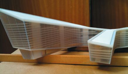
With the London 2012 restriction shackles off, firms can now talk about their Olympic designs. Klomps gave a great insight into how Zaha Hadid approached the design and manufacture of the diving boards in the London Aquatic Centre.
Using McNeel Rhino, the firm cleverly sculpted three diving boards of varying height using the same three sections. These were machined at real scale in foam, from which fiberglass moulds were made to cast the concrete. This was a great story of digital design and fabrication, showing the team’s excellent design flair. My only concern was that for known temporary structures, they looked like they were built to survive a direct nuclear hit.
In the debate following the presentations, a fairly black and white discussion took place on the place of 2D drawings in the design and construction process.
Some participants said that they have dispensed with 2D altogether, other than for contractual needs, while others such as Klomps strongly disagreed. She said 2D had a valid place and had to regularly stop her team from modelling a problem, wasting time, when it could be sketched in 2D much more quickly. The Symposium includes presentations from leading industry practitioners describing computational-based projects or thought leading research. This year SG had lined up: Tristram Carfrae (Arup), Michelle Addington (Yale University), Sarah Jane Pell (Artist & Researcher) and Ben Cerveny (Data Visualization Designer).
A major coup for SmartGeometry was getting Tristram Carfrae, structural engineer, Arup to present. Carfrae has helped design some truly amazing and award winning buildings, such as the National Aquatics Centre (Beijing’s Watercube) and is one of the world’s leading experts in lightweight, long-span structures.
He explored a number of designs where generative methods were used to come up with a non-linear solution to deal with site restrictions, leading to a more interesting building that structurally as good, if not better than standard designs. Conclusion SmartGeometry has a relatively unrelenting schedule over three days and covers such a broad range of topics and ideas that it can leave one a little bewildered, with no time to truly absorb the complexities or far reaching impact of a presentation. It doesn’t help that the event rarely runs to time. Thankfully the Symposium and sgTalkshops should be available to view online in the coming weeks and can be taken with a little more digestion time.
At the start, ten years ago, SG workshops were producing little more than CAD spirals with arrays, or unravelling curved glazing schedules. Today’s teams were designing complex vaulted structures, 3D printing them, then assisting an artisan fabricate the form, while using 3D scanning technology to compare the built form against the original design. SmartGeometry and the technology we have at our fingertips has come a long, long way.
■ smartgeometry.org
Bentley turns to the cloud for simulation
Event sponsor Bentley previewed a brand new technology that uses Generative Components and cloudbased simulation to explore hundreds of design iterations. Santanu Das, Bentley’s senior vice president for design and modelling, explained how studies have shown that most designs only undergo a few iterations. Time spent modelling and remodelling, setting up simulations, and processing bottlenecks are the big barriers to evaluating more alternatives. Those wanting to do an acoustical analysis, heat analysis or a solar insulation analysis, for example, don’t want to have to remodel every single time, explained Das “[The model] should be smart enough to self describe itself and prepare itself for that type of simulation.” Simulation is traditionally used for design verification, but Bentley sees a big opportunity for it to be deployed throughout the entire design process, using early stage conceptual models from the very beginning. “You can get a big ‘red, yellow, green’ as to where am I with my solar exposure, or where am I with my line of sight or my shadows,” he said. As the model progresses it should be able to be self-aware and provide feedback on how it’s handling the different analytics it’s exposed to, he said. Simulation shouldn’t be a serial process of build > analyse > modify and then analyse again, emphasized Das. “It should be integrated and it should be in real time and with Bentley’s cloud technologies this is all now possible.” Das was clear that the technology is not just about using the cloud to run more simulations. “You have to make the analytics talk to each other,” he said. “It’s what we call multi-disciplinary optimisations: the output of structural should influence the input of energy. The output of energy should influence the input of acoustics. We can’t work in silos anymore.” It’s also about the automatic generation of the different analysis models, which Bentley calls scenario management. “Using Bentley’s scenario management with our Generative Components we can optimise and automatically generate those models for you – by you giving the constraints and what kind of patterns that you want,” said Das. “All of those models are created and
uploaded onto our cloud and you can see we’ve designed them in real time and we compare them against many different scenarios.” Das gave an example where the system generated 60 different scenarios, but in theory this could lead to 100s if not 1,000s, leading to a much more optimal solution and helping make a building more efficient, both in terms of performance and cost. To handle all the processing, Bentley has partnered with Microsoft and is using its Azure platform. The technology is not just reliant on multi-threaded CPUs though: Bentley showed a slide highlighting GPU compute through CUDA. Bentley’s cloud-based simulation technology will be launched later this year. ■ bentley.com
Executive guide to BIM: part 1
What is Building Information Modelling and is it relevant to me? This is a question asked by many in today’s construction sector. This two-part guide will attempt to answer the questions that may arise relating to a BIM adoption strategy.
by Paul Woddy, White Frog
BIM is an acronym that is much used and very much misunderstood. It is not a new term — it was first coined in the 1970s — nor does any one party own it, commercially or collectively. This partly explains one of the problems with it: Because no organisation can claim ownership or oversight, clear definitions and standards have been slow to emerge and confusion has spread. This situation has been exacerbated by some parties inappropriately or tenuously jumping on the Building Information Modelling (BIM) bandwagon in an attempt to leapfrog the competition or re-launch existing products and / or services.
For many, the move to BIM can be more cultural than it is technological and the impact can be far reaching in terms of upheaval as well as reward. It is important to grasp the principles and methodologies of BIM, as well as the implications on the team workflow, but also to seize the opportunity to work more closely with other stakeholders in improved collaboration and co-ordination, often referred to as supply chain collaboration.
BIM is not a topic exclusive to architects, engineers and constructors and in the wider construction sector BIM is no less relevant, even if it is arguably misdiagnosed as more of a sideline issue.
If you are a manufacturer or supplier of products to the building industry then the use of BIM may range from creating a suitable library of virtual elements to match your products, to altering your manufacturing workflow to accommodate BIM data received electronically.
BIM libraries can be made available to designers who are specifying components, and hence act as a great new sales opportunity, but which BIM software or format do you opt for?
If you are a client, contractor, topographical surveyor, quantity surveyor or facility manager then BIM may have a part to play, but your interaction with it may be varied. For many it may be simply a case of ‘wait and see’.
The nature of the underlying database means that, once created, if an object is subsequently updated or changed, these changes reflect in all relevant 2D and 3D views simultaneously, and any annotation is also updated, thereby maintaining the co-ordination of the model as well as all views of the model.
If you only take one statement from this guide, let it be that the most important part of BIM is the ‘I’ in the middle.
Information is king. In the BIM methodology, data is collated, modelled, manipulated and managed, but always with an understanding of the object to which the data relates. Isn’t this just CAD with bells on? When drawing boards were (largely) replaced by monitors plus a succession of tablets, keyboards, mice and other input devices, developers of CAD software focused on mirroring the techniques and processes of the drawing office, whilst removing some of the repetition and making the job easier and faster along the way.
The adoption of BIM with all of the associated upheaval has been equated to this switch to CAD, but the consequences for the drawing office can be considerably more far-reaching. Technically, of course BIM is CAD in that CAD is Computer Aided Design, but pushing semantics aside, the industry has come to draw a distinction between the two, with the involvement of the computer being a foregone conclusion.
It is not simply a case of applying traditional techniques to a new technology, but the adoption of new methodologies and business practices that denote BIM. Aspects of BIM will replace the drawing production side of CAD as it will similarly replicate
If you only take ‘‘ one statement from this guide, let it be that the most important part of BIM is the ‘I’ in the middle. Information is king. In the BIM methodology, data is collated, modelled, manipulated and managed, but always with an understanding of the object to which the data relates ’’
some of the actions traditionally performed by spreadsheets and databases for quantitative analysis and component specification.
It is a common misconception that buying a piece of software is the answer to adopting a new business / design strategy. Also affected will be the team structure, job titles and project management; communication with suppliers and contractors; client deliverables; collaboration with other project stakeholders; fee structures and contract form; legal liabilities; insured risk and mitigation; and the benefits and rewards can be equally comprehensive, but only if the adoption of the process and workflow is managed well.
Buying the wrong software or pouring money into inappropriate training can result in an expensive and painful exercise. How and where do I buy BIM? Does Revit equal BIM and BIM equal Revit? Several misconceptions need to be explained, including the idea that buying a piece of software is the answer to adopting a new business / design strategy.
BIM is a methodology and a working process as much as it is a purchasing decision. Revit is currently the market leading BIM software and it does help facilitate this methodology if properly utilised but so would products from Bentley, Graphisoft and a myriad of other developers — even Microsoft Excel has a part to play. Each tool has ardent fans and fervent detractors and each has benefits and failures, none of which we will be looking at here.
The pros and cons of each platform need to be understood in the context of the unique office environment and the requirements therein. Best avoid the soapbox preachers from any one camp and remember to speak to the whole supply chain. Industry drivers Often the biggest driver for BIM adoption is the government, as it often represents the largest client with the weight to force technology and process adoption.
National governments across Europe, in particular in Scandinavia and the UK, plus various States in the US, have made progressively stronger announcements regarding BIM in recent years, many mandating the use of BIM methodology on all public works. Most follow a similar vein to the UK approach, which has initially dictated that from 2016 onwards, a Level 2 BIM methodology is mandated on all centrally procured public construction projects with IFC and COBie as the exchange formats for hand-over. These are very achievable targets in the short to medium-term but it is anticipated that as the market progresses and meets these objectives, the bar will be moved higher.
It is not that every design practice intends on winning public work, nor should a practice that precludes such work ignore this information as the effort and researching undertaken to validate this government decision has given the private sector the confidence boost it needed to move in the same direction. It is no longer early-adopter technology but something with a proven track record and a strong future.
In addition to the political drivers, the technological improvement in both hardware and software associated with BIM is driving the market forwards. The efficiency gains that can be made in adopting even a fraction of the features of BIM software can justify the often steep purchase and imple-
BIM cheat sheet
BIM is an acronym for Building Information Modelling. This might be stating the obvious but it is worth clarifying because some argue that BIM can refer to Building Information Management, and messaging from software firms can vary. Both interpretations are correct. But sometimes the word ‘modelling’ causes BIM to be wrongly pigeon-holed as ‘fancy 3D graphics’, especially when those writing about BIM tend to use fancy 3D graphics. So what does it mean? BIM can be summarised as a methodology which is fundamentally concerned with the collation and management of information relating to a construction project, manipulated through a 3D awareness of interrelationships between objects and their associated data. Follow that? This means that a virtual building model is developed and information is collated from manufacturers or through the decisionmaking process of design. This model is analysed, tweaked, tested and revised, before a full-scale replica is built on site. It is built twice — once in the virtual world and again in the real world. Drawings are no longer a prerequisite deliverable from a BIM workflow, but when required they, along with schedules and other deliverables are simply interrogations of this pool of graphical and non-graphical information. What’s the deal with data? One big difference surrounds text on a drawing; instead of information being entered using a text tool which is akin to sticking a post-it note onto a sketch, data is added as a property of the relevant elements which are placed within the model. Generic tags are then used to extract and report the captured information and annotate the drawing. If a change is made to the information, that change is reflected in all views and reports which reference those elements, even if that data is stored externally and associated through a unique ID which relates it back to the modelled element. So what technology do I need for BIM? BIM is a methodology, not a software tool; no one application can deliver the whole BIM picture, nor should it. Technically, BIM methodology could be applied using a pencil and a spreadsheet application, and it could equally apply to road, rail and infrastructure. Other terms can be used to describe the same process for different related sectors, such as Graphical Information Systems (GIS) in mapping and larger-scale project management; Facility Information Management (FIM) for electronic O&M manuals. OK that sounds reasonable To keep things simple, we are talking about BIM for building projects; it should be rich in non-graphical information; and built with reference to a 3D Model.
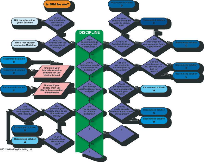
Is BIM relevant to me?
You may be thinking that BIM is only really of interest to architects and engineers, possibly contractors as well. Certainly those parties may chose to take on BIM and make it a core aspect of their business because it can improve the quality and efficiency of their delivery. But they are not the only people to
whom BIM is relevant. For those in less obvious sectors, the decision to get involved in BIM can be simplified with a succession of questions leading to the most appropriate solution: Issue A: You need to be aware of BIM and where it is being adopted, above and below you in the supply chain Action: Keep asking questions Issue B: It may be pertinent to supply BIM data as a sales initiative either in maintaining current position or gaining new market share Action: The most cost effective solution is to contract out building the components as the cost of maintaining the software and skills in-house would be hard to justify Issue C: Building BIM skills internally would be relevant and costeffective in order to interact with the supply chain and the manufacturing or maintenance process Action: Define a BIM Strategy, choose a primary software format and train or hire BIM-ready personnel Issue D: BIM methodology can deliver demonstrable efficiency gains internally
Action: An adoption strategy with return on investment should be strongly considered and regularly reassessed in the future if the numbers do not yet stack up Issue E: Full collaborative BIM involving the transfer and reuse of electronic data with one or more stakeholders makes adoption essential Action: A thorough software adoption and training strategy should be budgeted and planned The diagram on the following page is intended to lead through to one of the suggested solutions listed above
mentation cost.
These savings cannot be assumed however and the benefits promised by the chosen BIM software should be carefully reviewed against the associated expense of delivery in the traditional workflow; or the added financial benefit or delivering a new service.
Educational institutions have access to pretty much all the software they need but they rightly have a tendency to only adopt the technology which supports or enhances the message being taught in the wider curriculum. Software is rarely the topic of the course but usually just a means of delivering the expected result. BIM methodology transcends this and is both a delivery mechanism and a topic worthy of academic study. Many colleges and universities are now offering qualifications in BIM methodology and the principles form a core of many design courses.
Understanding of the benefits to be had from a BIM-committed supply chain is growing in the UK. Communication is a key aspect of BIM, and better communication through multiple representations of a problem or design intent, allows for a better understanding of a given scenario.
The impact of any proposed solutions is seen on all surrounding objects, therefore allowing for more informed decisions and various options can be reviewed and discussed in order to reach the best result with full understanding of the costs and rewards of each alternative.
This is why the contractor and the client can expect a more streamlined and efficient design process, which in turn is why many of them are mandating BIM on all future projects — a trend which has been accelerated by the government pronouncement to the same effect.
BIM terminology and principles
Here we explore some common Building Information Modelling (BIM) terms and take a look at the wider implications in preparing data that may be used in design, construction and maintenance. The single building model The single building model relates to the idea that all stakeholders participate in the editing of one single file, adding their work and elements to a central pool.
It is a common misconception that the concept of BIM and the idea of a Single Building Model are the same. This is also one of the biggest fears for insurance underwriters who see a free-for-all where every stakeholder is working on one shared file, adding and modifying the elements, with other trades working around them, potentially getting in the way and accidentally making changes.
It raises serious questions regarding the ownership of elements and associated permissions and liabilities, only some of which are answered by the technology. A lot of these issues currently have to be handled through trust and management and are a potential hotbed of disagreement and blame.
The Single Building Model is at this point, a fallacy, both from a technological perspective and from a cultural perspective. The software and hardware would preclude all but the smallest commercial projects, and the contractual environment within the supply chain is not ready for the required workflows.
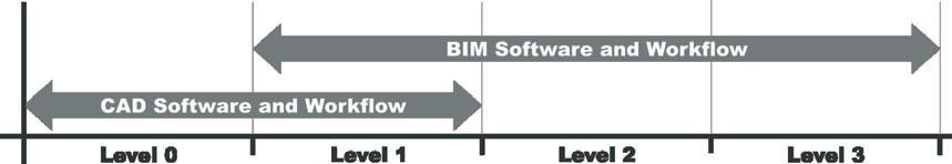
Case studies are available demonstrating the concept of a single file, worked on by all parties, but this has been in limited and controlled circumstances, on smallscale buildings. Given the right hardware and software, it is feasible to do, but that does not make it right or advisable. BIM or BIM It is impractical to suggest that any organisation will take a single step to go from reliance upon 2D drawings using CAD to a full collaborative BIM workflow. In fact there are four defined levels of BIM adoption:
Level 0
Level 1
Level 2
Level 3 2D CAD 3D CAD Siloed BIM Collaborative BIM
As can be seen in the above graphic, there is overlap between the levels of CAD and BIM use and there is a natural process of ascendancy that is commonly followed during the adoption of BIM.
Level 1 — Is it CAD or BIM?
It is not uncommon to find that software such as Revit, ArchiCAD or other BIMcapable applications are used to deliver drawings, but all BIM aspects are effectively ignored in the process. This is no better than 3D CAD and the model is used purely for aesthetic and graphical interrogation, effectively missing the ‘I’ out of the acronym and leaving a Building Model.
This generally occurs when there is a lack of understanding and training and usually stems from a decision — forced or otherwise — to adopt BIM and thinking that the price of this adoption is the cost of a software licence.
It is a common mistake to imagine that because a company is staffed with intelligent users, they will be able to train themselves and get on with it. Whilst this may be true, in terms of replicating old processes and getting the new software to ‘fit-in’, it does not allow those users to realise the benefits of the new workflows that deliver the real return on the investment. You can only search for help if you know what to search for.
Big BIM and little BIM
So having decided to use the missing ‘I’ and add information to the modelled elements, users move firmly into the BIM ecosystem. But adopting BIM-capable software and methodologies for in-house production of deliverables is only the first step in BIM and although the benefits of doing so are measurable, it is only when BIM data is transferred between stakeholders and used in a collaborative sense that the full capabilities are realised.
Level 2 — Siloed BIM
Level 2 BIM is often referred to as Siloed BIM or Little BIM, so called because BIM is used in isolation of outside circumstances. This is not necessarily an indication that the software is badly-used or under-performing, but is often seen as a means to an end in terms of production, alteration and management of drawings and is often the first step in a BIM implementation — learning to walk.
Often various stakeholders use BIM for their own purposes in-house and yet are unaware of how others on the project are preparing documentation for the client or contractor. Each party delivers a set of drawings and instructions as per the contractual deliverables, whether they use the latest BIM tools or not.
Level 3 — Collaborative BIM
Also known as Collaborative BIM, iBIM or Big BIM, this is the ideal to which we should aspire as an industry.
It does not dictate that all parties utilise the same software platform, but that electronic communication between platforms is fully explored and exploited.
Ideally, data is regularly passed between all parties and frequent meetings see the collation of the virtual building design incorporating all disciplines. Such meetings would identify clashes and assign resolution of issues.
Each team should have access to the BIM data of other parties as a backdrop to their design activity and the client or contractor would be able to see and interact with the process.
The final deliverable of the workflow would be a fully laden 3D model containing all associated meta-data. The production of drawings might still be required by construction workers but need no longer be an integral aspect of design delivery.
With energy prices expected to rocket in the coming decades, the existing building stock is coming under ever closer scrutiny. Older, less efficient structures are being assessed and options being explored and priced to renovate or replace.
Many of these inefficient buildings are owned and maintained by public bodies such as councils, universities and hospitals, and with limited budgets available in the public sector, this task has to be performed with intelligence and as much self-sufficiency as possible. BIM does have a large part to play in the survey and assessment as well as the development of refurbishment options or replacement opportunities.
The construction sector will emerge from the current financial squeeze in a leaner, more robust form. Those companies that survive and form the vanguard of the next boom will demonstrate an awareness of this cultural change and be fully conversant in the technologies, methodologies, implications and workflows of BIM. What dimension? For the practical purposes of BIM, there are six ‘D’s that have relative industry agreement: 1D 2D 3D 4D 5D 6D A Point Line Drawing Modelled Solids and Surfaces Time and Sequence Costing Building Lifecycle Management and Facilities Management The above will have a greater or lesser involvement in your BIM workflow, depending upon your discipline and choice, but also on the demands of the clients and project stakeholders.
BIM data produced by an architect can often be used by engineers in analysis applications; quantity surveyors in cost estimating; contractors in the planning and construction phase; and ultimately used as the basis of a facilities management handover, but all of these uses may have implications on the way that a model is constructed and the type, style and formatting of information that is collated and compiled. These requirements may mean additional work to the model or even efforts that run contrary to the requirements of others.
This statement may seem contrary but in truth, the model that is produced by the concept architect at the commencement of the design is a very different model containing vastly different objects to the one which is used as an facilities management tool at the end. It is neither possible nor cost-effective to encompass all possible uses into an element from the outset, but most BIM workflows allow for the easy swapping of components and the addition of new meta-data to suit a new usage.
■ whitefrog.co
Next issue
We will go into greater detail on BIM workflows, when a model progresses from concept to construction and FM. Our discussion will cover the benefits and implications of adopting BIM, including changes to teams and workflows.

The No. 1 Choice. FARO Laser Scanner Focus3D
Simplify and speed up your projects with the no. 1 choice for 3D Documentation! The award winning compact design and touch display makes it easy to use. Multiple sensors provide rich point cloud data to deliver speedy post processing with Scene Software. No wonder it is the preferred option.
Call us at 00 800 3276 7253 for a free demo or visit us at Facilities Show 2013, Birmingham, Hall 2, Stand No. 2F46.
More about the Laser Scanner at:
www.faro.com/focus
More information
Missing a trick
Stuck in their old ways and reluctant to invest, quantity surveyors are missing out on the rich data benefits of Building Information Modelling (BIM).
by Rob Charlton
The adoption of In 2006 the potential of this Building Information data was clear to me so I began Modelling (BIM) has having a number of conversanow moved past sim- tions with the leading quantity ply being a 3D design tool. surveying (QS) organisations in Landlords, investors and build- the country. I was told then that ing users have started to realise Rob there was little interest. The that BIM goes far beyond visu- Charlton reasons were that these organialisation and clash detection. sations were either developing The shift towards BIM is increasingly about data gathCEO Space Architecture their own software or they could not trust the quality of ered throughout the design and the information supplied. construction process and how it can be Around the same time we scheduled all used positively. of the floor areas for a secondary school.
Several years ago I referred to this data The quantity surveyors did not trust the as the marmite of BIM. Marmite is the bi- information so took our paper drawings, product of the brewing industry. At some digitised them and completed a take off. point, someone thought it would be a good Seven years later there has been little idea to put this waste yeast extract to use, progress and the reasons are largely the to bottle and sell it. It is now a global brand same. making millions of pounds of profit. BIM pushes out lots of data that can be
The data output from the modelling pro- analysed and reported on. The architect is cess is the same as marmite. The produc- not the best person to use this data. The tion of the model means there is a lot of engineer is using some of it, as is the coninformation that can be used. structor at certain points.
There is a need for someone to take this information and use it in the design constructions and operation of a building. The quantity surveyor has the right skills to manipulate this information but seems very reluctant to do so.
Over the last few years quantity surveyors have been chastised for not getting involved, yet I have seen little change in attitude. This has led me to consider the reasons for this reluctance to get involved despite the ample opportunity.
One thought is that generally the QS software of choice is Microsoft Excel — a low cost technology. This reduced overhead has gone straight to the bottom line. Any commitment to BIM would mean a commitment to software, hardware and training.
In comparison, a medium-sized architectural practice will spend six figures every year on software alone. For a quantity surveyor to invest in BIM, it would mean a significant reduction on bottom line profit.
A simple explanation for lack of engage-
Quantity surveyors often do not trust the information in BIM models so rely on paper drawings to complete the survey process

ment could be that surveyors enjoy measurement. It is a manual and laborious task that takes many hours of expensive resource. New software, on the other hand, can deliver quantum from the model in seconds. Trust the data But can the data always be trusted? Of course it can. It cannot be any worse than human error in measurement.
We have all had projects where the quantity surveyor has missed something or measured incorrectly. However in reality, I think this is only a very small blocker and not one of the main reasons for a lack of adoption across the profession.
My next thought is a little more personal and is aimed at the partners of the many surveyor practices in the UK. In the 1990s, the QS profession was very commercial and during this time, looked to grow and increase opportunities in the design process. It took hold of project management opportunities as well as embracing planning supervision when new regulations were released.
At the same time architects focussed more and more on design and allowed these roles to move away from the lead consultant.
This generation of partners who were so entrepreneurial at the time are now at the twilight of their career. They were the sharp brains of their time and are now unwilling to roll the dice once more so near to retirement. Their focus will be on the Tuscan Villa rather than new software or hardware.
The sway towards the New Rules of Measurement is my final theory. The Royal Institute of Chartered Surveyors has been promoting NRM for a long time now but the first section has been issued while further sections have failed to materialise. This means any potential future structure of information is in a state of flux. QS firms as a result are reluctant to commit to a potentially out-of-date framework.
RICS will tell you that NRM is an international standard. It is not. It is the RICS standard that is used internationally. Until procurement and measurement processes are aligned to those used internationally, we will always be left behind.
The challenge for the QS profession is that clients see the benefits of a clear understanding of the data throughout the lifecycle of a project from international case studies. Quite rightly they want to see this level of detail on their own projects.
Unfortunately the QS business is not responding at all.
While surveyors stand still others are seizing the opportunity to exploit the data. New programmes and dashboards are being developed which can interrogate information throughout a project’s lifecycle.
Quantity surveyors have the best skills to interpret and review the information; however at present they are looking very flat footed and may find it difficult in future to demonstrate their value to the process.
Image: bradleym I stockphoto.com

A lack of understanding of how buildings behave in use, including those specifically designed to be energy efficient, has undermined the progress of sustainable construction and retrofitting initiatives
One track mind
Rich data from wireless sensor technologies is helping track energy performance in sustainable construction and retrofitting initiatives.
by Professor Elena Gaura
Alack of understanding of how buildings behave in use, including those specifically designed to be energy efficient, has undermined the progress of sustainable construction and retrofitting initiatives. No-one knows if the measures have led to real energy-savings or not.
Research has overwhelmingly shown that how a building is used is the critical factor, with up to 200% variation in energy consumption from identical buildings.
Evaluation of a building’s performance is not a common part of construction and commissioning, the assumption being that a building will perform according to the design spec. The shift towards sustainable building, as well as retrofitting campaigns, will be seriously undermined without clear and ongoing insight into how people and eco-buildings work together, and the steps that can be taken to ensure what is intended can be delivered in practice.
Information on behaviour will be a critical part of ensuring buildings are genuinely ‘resilient’, flexible and adaptable enough to deal with challenges from climate change, alternative use, and for the integration of new technologies without the need for major and expensive re-building. This kind of rich data will be important for Building Information Modelling (BIM), providing the basis for including an energy performance in-use dimension to the modelling.
Trials of new low-cost, wireless sensor technologies with the Orbit Housing Association have shown the potential for large-scale use of sensors a real option for closing the performance gap. New Wireless Sensor Networks have been developed that meet the needs of users in the built environment sector: low-cost, robust, easy to deploy and to interpret the data provided, and long network life on minimal battery power.
Intensive monitoring provides the opportunity for rapid insights into how any new technologies work, which are working and which are not. It is possible to identify precisely which technologies deliver the best value in terms of in-use performance, and to streamline procurement, feed back the learning into the future planning and design process and establish a stronger foundation of confidence in eco-friendly measures.
In the research, more than 200,000 items of data were generated from each sensor for every week of monitoring — tracking temperature, humidity, CO2 levels and VOC (Volatile Organic Compounds), compared against consumption of energy and water — and crunched into a form that can be analysed by non-experts. This way landlords can find out whether excessive carbon emissions are caused by the behaviour of residents, problems with heating systems or in the fabric of the building itself.
On the basis of the 70 homes monitored and analysed, Orbit has started making decisions on investment and areas for cost-savings. In one of the studies, the work has highlighted weaknesses in newly installed heating systems, which provided the evidence for calling back contractors for repairs.
It has also pointed at specific issues around occupier behaviour, which can now be addressed through information packs on the use of new technologies installed, the need for a site attendant to guide occupants and open house events for tenants to get help in managing their property. As a direct result of the research and work with Orbit, tenants have started to see savings of £250 per year in energy costs. In a survey of experiences, and despite the recent increases in levels of charges, 75% of tenants said they were satisfied with the size of their energy bills.
Orbit has saved £100,000 by identifying early some defects in the Passiv home site.
Energy performance in-use data will be important for the development of BIM as standard practice, with the potential for delivering cost-savings for developers and landlords over the full life-cycle of buildings. Professor Elena Gaura is from the Low Impact Building Centre, Coventry University
2 3 4
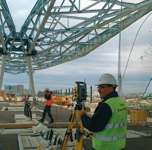
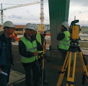
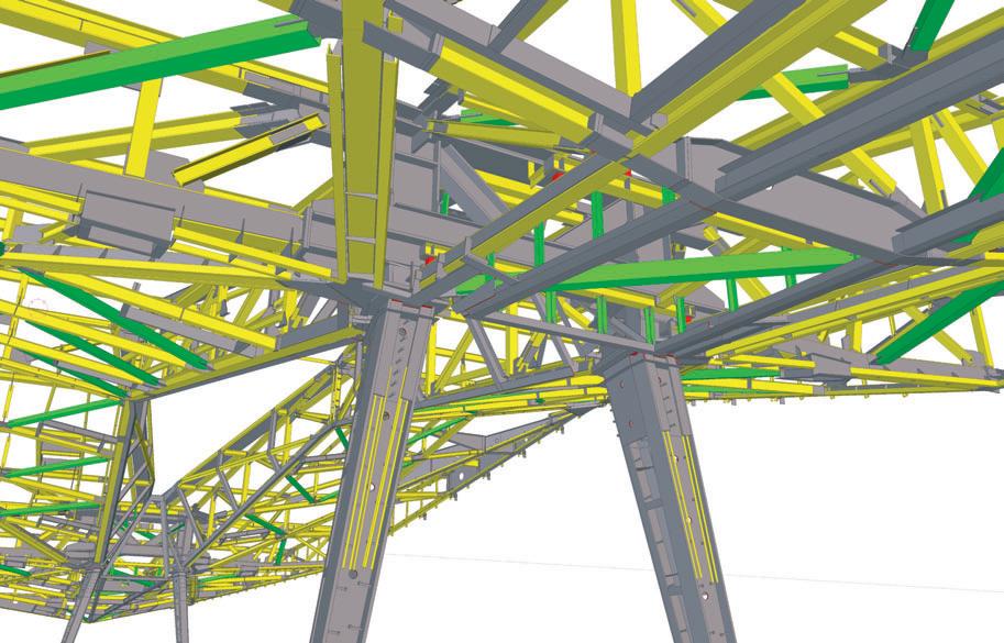
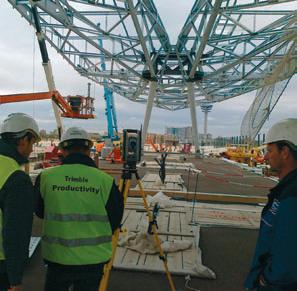
Thirty-five experts from Unger Steel Group used Tekla’s BIM software to plan, produce and assemble the diamond trusses of the partially transparent roof of the Vienna Central Railway Station. Now when the trains arrive at the station, passengers see the first glimpse of the city through the roof.
1 The new Vienna Central Station roof was made of 14 unique diamond shape steel trusses 2, 3 & 4 Using Trimble Total Station on site
Vienna Central Railway Station
The new Vienna Central Railway Automating production From Total Station to Tekla and back Station is a major European traffic The required data is transferred directly The workflow for positioning the roof parts hub. When completed in 2015, from the design office in to the DSTV file for- moved in rounds. Unger’s team measured about 145,000 passengers and mat and interfaces with the cutting machines the structure with Trimble Total Station, 1,000 trains will pass through the station in Unger’s workshop. The process means imported the data to Tekla Structures, every day. The project has an attached shop- production can start immediately after com- adjusted it, and exported the modified data ping mall, residential buildings and park. pletion of planning. Transferring fabrication back to Total Station for positioning. Unger Steel Group had to work with preci- information automatically to production As any inaccuracies would have affected sion on this crowded site and include other machinery means errors are avoided. the composition, the Unger team performed project parties. control measurements continuously in case
Unger was contracted to complete the Punctual logistics the components would carry tolerances from roof which covers the tracks, with a com- Unger chose Tekla because it had to work fabrication or transport. On the connection plex geometry of 14 unique diamond- punctually: it was crucial to have the right points of the diamond trusses, the team meashaped steel trusses. It used Tekla material at the right place. sured the structure, downloaded the measoftware and Trimble Total Station to com- Unger’s team had to assemble the complex surements into the Tekla model and after plete the work. diamond trusses in a very limited space. The this planned and manufactured the connecpieces arrived to site just before they were tion parts. On site, they also marked building What’s in the model? bolted together. The site staff assembled the axes with Trimble Total Station. Tekla created constructable steel structures, first trusses while the workshop team promodelled and detailed the Time, money and workflow main structure and substruc- Smooth workflow between tures like cable channels, extracted data and drawings for production and assembly, Duetothe ‘‘ complexityofthegeometry office and site is the goal of every construction company, and according to Unger, Trimble and simulated welding andverytightschedule,constructionwith and Tekla together take their sequences of the complex components. 2Dplanswouldnothavebeenpossible customers closer to this goal. BIM and automated data Up to ten designers worked on the model in multi-user mode. Unger imported the ’’ transfer accelerated the project. With Trimble Total Station, Unger’s own staff could meaarchitect’s model as 3D DWG files to Tekla duced the remaining ones. The entire pro- sure the structures to save on expenses of Structures for design and detailing the dia- cess from cutting one truss to its final assem- external surveyors. They transferred the mond trusses. As numerous parties operated bly took on average three and a half months. measurements of the built structure directly on the huge construction site, Unger includ- to Tekla to save time and labour and avoid ed platforms with rails and concrete founda- Trimble Total Station entering the measuring data manually. Tekla tions to the model in order to notice and solve Unger used Trimble Total Station with Tekla eased the logistical challenge with automatipossible clashes in the design phase. for the first time to assemble the diamond cally generated transport lists and aid in contrusses. Unger assembled the roof compo- trolling production and assembly sequence. BIM everywhere nents while they hung from a crane, and the At Unger BIM does not stop at the design team needed exact position information for Collaboration using Tekla BIMsight office door. The company configures each lifting and fitting the components correctly Unger chose Tekla BIMsight for collaboranew version of Tekla Structures according at 15m above the platforms. tion with architects and structural engineers. to specific standards, which enables it They used the combination of Tekla and Each party had the building information to plan specifically for cutting and Trimble in a preassembly workshop to mea- model available and could work together, production. sure the components after welding, to spot including production and installation teams
Unger created transport lists and surveys possible manufacturing tolerances before on site. Tekla BIMsight was also used for the directly from the model in Tekla and used it assembly, and later to control the position of approval process in the planning phase. to control production and assembly. the structure and put the parts together. ■ tekla.com
Scan 3XS 8GB of RAM, but Scan has managed to pack in an impressive 16GB into this GW-MT15: machine, populating two of the four DIMM slots with 8GB DDR3-1600 modules. Quadro K600 For those that work with small assemblies much of this will probably go unused, so it could be worth scaling down An overclocked Intel Core i5 to 8GB if budget is tight. 3570K CPU and Nvidia’s Product spec To handle 3D models Scan brand new Kepler Quadro has included Nvidia’s brand K600 GPU combine to deliv- ■ Quad Core Intel new Quadro K600 graphics er an enviably low cost CAD Core i5 3570K Ivy Bridge CPU (3.4GHz card. The 1GB card is ideal workstation overclocked to 4.4GHz) for entry-level CAD, but will start to show its limitations Sub £1,000 workstations used ■ 16GB (2 x 8GB) Corsair PC3-12800 when working with large to mean a major trade off in (1600) memory 3D models, particularly when most areas — CPU, memory, ■ Nvidia Quadro K600 (1GB DDR3) displaying realistic materials, hard drive and graphics. But, as graphics using Nitrous in 3ds Max Scan’s latest entry-level machine ■ 120GB PNY XLR8 for example. demonstrates, the sacrifices do Series SSD + 2TB 7,200RPM Seagate In terms of storage, Scan has not have to be nearly as big as Barracuda 6Gb/s opted for a dual drive setup: a they used to be. SATA hard drive 120GB PNY XLR8 Solid State
Scan’s 3XS GW-MT15 is ■ Gigabyte GA-Z77D3H motherboard Drive (SSD) for operfocused squarely on entry-level ■ Microsoft Windows ating system and 3D, but still provides raw CPU 7 Professional 64-bit applications performance. Overclocked to 4.4GHz the quad core Intel ■ 3 year warranty - 1st year onsite, 2nd and 3rd year return and sizeable 2TB Seagate Core i5 3570K processor packs to base (parts & labour) Barracuda a huge punch for CAD and BIM ■ £940 SATA drive software, where clock speed is king. 3xs.scan.co.uk for data. Considering
This ‘Ivy Bridge’ chip is a the price of cool £70 cheaper than the pop- the machine ular Core i7 3770K and there should be this is pretty impresvery little noticeable difference in day-to- sive, though I would day modelling operations. personally allocate a bit
The main distinction between the two is more budget to the SSD. that the Intel Core i5 3570K does not sup- For an additional £26 port Intel HyperThreading, which should you can upgrade to a give a welcome 15% boost in most ray trace professional PNY renderers. 120GB Prevail Elite,
So, unless rendering is an important which is not only rated by part of your workflow, consider it money PNY as being 10x higher in terms well saved. of its long term endurance, but our tests
Most entry-level workstations ship with confirm that it is significantly faster than the consumer-focused PNY XLR8. £26 well spent I’d say.
For what is positioned as a budget workstation it is good to see Scan has still managed to present the components in a quality chassis. The CoolerMaster Silencio RC-550 is solid in construction, provides easy access to the hard drives inside and also includes some handy top mounted USB ports.
With a substantial CPU heat sink and insulated with acoustic foam, the machine is also incredibly quiet in operation. However, with the CPU rated at 77W and the GPU at 41W there is not a huge amount of heat being generated inside so the fans should not be taxed too much anyway.
Overall, the Scan 3XS GW-MT15 is an impressive entry-level machine, which, thanks to its overclocked CPU, can mix it with the best when it comes to raw performance in CAD and BIM software. The only real limitation as far as CAD is concerned is with graphics where large models, particularly those presented with realistic materials, could become a little sluggish on screen. Other than that, even with a few tweaks here and there, perhaps to upgrade the SSD, it is possible to keep it under that all-important £1,000 Threshold. Impressive stuff from the Bolton-based system builder.
Greg Corke

Nvidia’s new Keplerbased Quadro GPUs
Nvidia has three new CAD-focused Quadro GPUs based on its Kepler architecture.
The Quadro K600 (1GB DDR3) (£149); Quadro K2000 (2GB GDDR5) (£389); and Quadro K4000 (3GB GDDR5) (£829) are for entry-level, mid-range and high-end users respectively.
The cards join the Quadro K5000 (4GB GDDR5) (£1,559) which is really reserved for ultra high-end CAD, powerwalls or design viz. ■ nvidia.co.uk/quadro