5 minute read
OpenBIM


Close control with OpenBIM
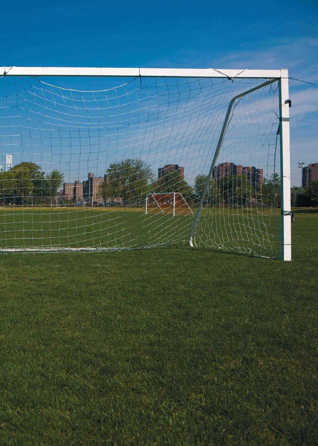
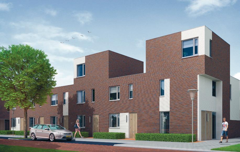
The 26-house project in Zwolle,
Netherlands was created through integrated design. Rendering produced by archivision.nl
ZEEP architecten has invested in OpenBIM and integrated design processes. The result is better productivity, quality and customer satisfaction.
Acollaboration between three cooperating disciplines: architect, engineer and installation consultant addresses a 26-house project in Zwolle, Netherlands (pictured), through integrated design.
ZEEP architecten, winner of the 2010 ‘How Smart Is Your BIM’ contest, worked alongside building structure consultant Vericon, an experienced Tekla user, and installation consultant Veccins3d, which works with DDS-CAD. The three firms agreed to collaborate in Building Information Modelling (BIM) and to monitor data quality by an independent check on modelling — and design errors.
ZEEP architecten chose to use Solibri Model Checker from Kubus architectural solutions, its BIM-partner and ArchiCADdistributor. After a test phase, ZEEP concluded that Solibri could be used on various projects: internal, small projects and bigger projects in which collaboration is needed. Zeep architect Ronald van Aggelen says Solibri is the “unifying factor” for all these projects.
“Solibri works as a control system,” he says. “Solibri helps the team improve the quality of our work. It is an objective tool to monitor if the model meets predefined requirements.
“The beauty of this software is that even without coding during the process of elaborated design, all quantities can be extracted from the model.
“The way in which the design is created is independent of the working method or the used software. We strongly believe in this OpenBIM way of doing things.” Working together The starting point in exchanging information between the various construction partners is Industry Foundation Classes (IFC).
IFC-data is stored in an IFC-server where Solibri is used as a shell. Solibri then monitors and checks the quality of both incoming and outgoing IFC files.
It is increasingly important to share information with other partners in the building process, Mr van Aggelen says. “Not only does that reduce failure costs caused by poor communication, it also optimises our internal processes.
“By using a BIM model and the exchange of transparent, unambiguous data we are forcing ourselves to the limits to get the best from the model.”
By way of example Mr Van Aggelen says: “We are able, by the use of Solibri, to answer any question about the building in approximately 10% of the time we normally spend.”
The move to greater co-operation with partners has meant a change in processes, Mr van Aggelen says.
“Construction partners are — almost by nature — wary of each other. This has to be overcome and we have come a long way with our partners on this level.
“Since working with Solibri my decisions are better founded. All partners are aware of the benefits of doing business this way. Design optimisation The use of OpenBIM during the design (ArchiCAD, Tekla, DDS-CAD, and Solibri) has ensured that the building permit was submitted within six weeks from starting the design.
Mr van Aggelen is pleased with the quick turnaround of the project, as is the client. “We also ensured an end product with a higher quality than the sum of its parts,” he says.
The project is ready for construction, marketing materials are made and the construction documents will be manufactured regarding the specifications of the contractor, directly from ArchiCAD.
The contractor will receive directly unsolicited information such as quantity surveys and costing data.

House of Hanover
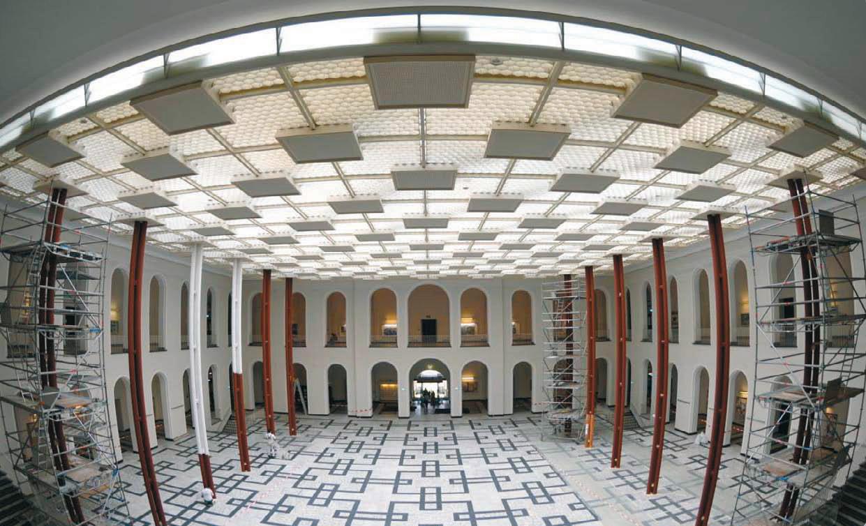
Digital measurements at Leibniz University with the faro focus3D laser scanner.
The recent refurbishment of a stunning glass roof over Guelph castle courtyard at the Leibniz University of Hanover was never going to be easy. The acclaimed institution wished to reglaze the glasswork using aluminium profile construction with highly insulated Schüco elements to improve its energy efficiency.
The listed courtyard is supported by a steel structure, with a total area of 1,200 square metres. Existing survey documents of the spatial support structure, made of steel tubing and double I beams, was old and imprecise, and did not provide all the necessary measurements.
Langenhagen-based Masche Metallbau was chosen to carry out a 3D survey, which was provided by Laser Scanning Architecture led by architect J Rechenbach. The steel substructure was measured in 12 individual scans, with the data transmitted to its inhouse CAD department for planning work.
Laser Scanning Architecture was able to generate the 3D digital image of the complete geometry within two working days. The laser scanner was on site for only three hours. In comparison, manual measurement would have taken about 40-60 hours of work — without the assurance that every dimension had been determined to the last detail. Scanning with Faro Laser Scanning Architecture used Faro Scene software for photo-realistic display of the recorded data. The scan was read into Autodesk Navisworks, which made it possible to combine scan data with 3D data from other sources.
A comparison of target and actual values was carried out, in which the scan data was presented, superimposed on the newly created CAD plan so that deviations immediately became visible.
Planning errors were systematically avoided early on. In this case, the faulty production of a single large aluminium-glass element would have been more expensive than the entire 3D measurement of the object. AutoCAD Architecture Detailed drawings were made by Masche Metallbau in 2D mode using AutoCAD Architecture. The 3D point cloud model was “sliced” randomly to show the true geometry of the steel substructure at the desired position and to plan the glass elements of the roof.
The freely available Autodesk plug-in, Cloud Point Extraction, was applied directly in AutoCAD, which enabled complex 3D models to be reduced to 2D content quickly and easily. This allowed all the desired measurements to be made and the 2D details to be worked out rapidly.
Once the basic geometry had been determined and the axis spacing of the support points specified, the component library of the Schücad software was accessed to incorporate the profiles to be constructed in CAD. Conclusion Using 3D scanning and documentation allowed a high degree of planning reliability during the construction process. It enabled the architect and engineers to precisely portray the as-built condition in this very complex roof geometry, in an older building in which deformations may have occurred.
The successful completion of the construction project shows how accurate digital surveying data can be and the benefits 3D documentation technology offers for construction applications in surveys and architectural monument preservation.