This publication was supported by the Cultural and Educational Grant Agency of the Ministry of Education, Culture and Sports of the Slovak Republic (KEGA) under contract No. KEGA 009 TU Z-4/2023 „Preparation of Multilingual Electronic Study Materials to Support the Internationalization of Education in Study Programs Fire Protection and Safety“.
Author:
prof. Bc. RNDr. Danica Kačíková, MSc., PhD.
Technical University in Zvolen
Theory of Combustion and Fire Dynamics
Educational Texts
Reviewers:
prof. Bc. Ing. Linda Makovická Osvaldová, PhD.
prof. RNDr. František Kačík, DrSc.
University of Žilina, Žilina, Slovak Republic
Technical University in Zvolen, Zvolen, Slovak Republic
I. - 2025, 172 pp. (8,39 AH, 8,54 VH)
Document form: electronic (online PDF)
Publisher: Technical University in Zvolene
Technical University in Zvolen
prof. Bc. RNDr. Danica Kačíková, MSc., PhD.
The manuscript has not been proofread. The author and reviewers are responsible for the professional and linguistic level of this publication.
ISBN 978-80-228-3507-7
All rights reserved. No part of the text or illustrations may be used for further distribution in any form without the prior consent of the authors or the publisher.
Theory of Combustion and Fire Dynamics
Danica Kačíková
Preface
The publication contains selected presentations related to the theory of combustion and fire dynamics. The text is compiled as a set of presentations for the mandatory subject with the same name in the 3rd-level study program Fire Protection and Safety in the field of Safety and Security Sciences.
The textbook is divided into parts:
1 Theory of Combustion
2 Application of Physical Chemistry, Chemical Thermodynamics and Combustion Kinetics
3 Fire Dynamics in Fire Protection and Safety, and Fire Suppression
4 Dynamics of Internal Fire Development
5 Dynamics of Outdoor Fire Development
6 Liquid Fuel Fires
The publication is a planned output of a project supported by the Cultural and Educational Grant Agency of the Ministry of Education, Culture and Sports of the Slovak Republic (KEGA). under contract No. KEGA 009 TU Z-4/2023 “Preparation of Multilingual Electronic Study Materials to Support the Internationalization of Education in Study Programs Fire Protection and Safety”. Project leader: Ing. Veronika Veľková, PhD.
The author of the publication with title “Theory of Combustion and Fire Dynamics”, prof. Bc. RNDr. Danica Kačíková, MSc., PhD., is a member of the research team.
Introduction
Why learn chemistry of combustion?
Chemistry explains the basic theoretical principles of combustion, which are important for understanding the laws of fire origin, development and spread. Selected chapters of chemistry are part of fire dynamics, which brings together several disciplines to better understand the nature of fire. These include chemistry, material science, fire science, mechanical engineering, fluid mechanics and heat transfer. The goal of fire science is to determine how each of these aspects of a fire’s circumstances impacts or influences its behaviour.
Fire dynamics is the study of how fires begin, grow and evolve over time. Researchers have generated experimental results and computer models to explain how fire dynamics taken at the most basic level, the fire triangle, applies to the fireground.
Why learn fire dynamics?
During fire suppression, firefighters can be confronted with a rapidly changing fire environment. And while many firefighters focus their training on the manipulative tasks of suppression, many fire fighter injuries and deaths are attributed to the lack of awareness of the fire environment. Furthermore, understanding fire dynamics provides firefighters the tools to anticipate and respond more effectively
Fire dynamics can provide a fire officer or a firefighter with means to understand how a fire will grow and spread within a structure and how best to control that growth.
Author
Theory of Combustion and Fire Dynamics
1 Theory of Combustion
1.1 Combustion and fire
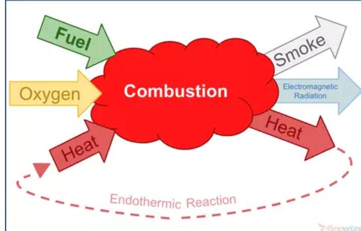
- combustion is a chemical reaction involving fuel an oxidizer – typically the oxygen (O2) in the air (Fig. 1.1)
Fig. 1.1 Scheme of combustion (https://firewize.com.au/definition/fire)
- the distinction to be fire or combustion is that significant energy has to be released
- in scientific terms – combustion and fire are synonymous
- in conventional terms – the fire is combustion that is not controlled
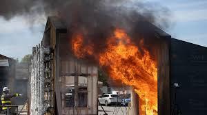
- fire is a chemical reaction that involves the evolution of light and energy in sufficient amounts to be perceptible (Fig. 1.2)
Fig. 1.2 Fire (https://www.instagram.com/p/C0watxjutwD/)
- the colour associated with fire might be blue from formative chemical emitters in a flame or yellow to red from light emitted by soot in a flame or smouldering char
- but: the burning of hydrogen (H2) with air or oxygen produces only water vapour, although significant energy is produced, we would not visibly see flame
- fire is combustion and combustion is a chemical reaction of significant energy release to cause damage
- sufficient damage can be assessed as harm to human tissue or irreversible damage to materials
-natural materials are hydrocarbon-based fuels: those composed of atoms of carbon (C), hydrogen (H), and perhaps some oxygen (O) and nitrogen (N)
- man-made materials have been added to this array of fuels (molecules) with the addition of chlorine (Cl), bromine (Br), fluorine (F), and other atoms
- wood molecules consist of the atoms involving H, C, O
- polyvinyl chloride (a plastic) contains H, C, and O plus Cl atoms
- polyurethane (another plastic) contains H, C, and O plus N atoms
Fig. 1.3 Combustion of polymer material (https://www.linkedin.com/pulse/fire-santosh-upadhyay)
- the additions to the H–C–O base complicate the nature of combustion products and their potential threat to the environment
- the other elements, even without the addition of oxygen could meet combustion (Fig. 1.3)
- fire or combustion is simply a chemical reaction that can suddenly occur to release significant energy with a relatively high temperature
- the formation of new molecules from fuel and oxygen molecules gives off a distinct amount of energy
- this energy comes from breaking the binding forces that held the original molecules together
1.1.1 Fire triangle and tetrahedron
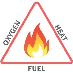
- a fire triangle is a concept used to describe the component needed for fire (Fig. 1.4)
Fig. 1.4 Scheme of fire triangle (https://fireaction.co.uk/news/fire-triangle-explained/)
- the elements of the fire triangle are essential to the existence of a fire
- the triangle consists of fuel (1) combining with oxygen (2) in a chemical reaction to release energy (3) and other chemical products
- the energy released by the reaction causes heat to be transferred to the solid or liquid fuel to maintain vaporisation into gaseous fuel and to maintain the temperature to ensure that the chemical reaction persist
- the combustion is a series of chemical reaction with many intermediate species
- a sufficient temperature to produce a chemically active species might initiate the first step in the reaction
- this active species, the molecules without the full electron structure, they are called radical and are highly reactive
- they would be unstable and prone to combine with another species
- this process is called a chain branching reaction
- the chain branching is an intermediate chemical reaction that always produces two unstable species
- if each radical reacts with any intermediate molecule to form two more radicals (chain branching), multiple and increasing reactions can occur among the radicals and intermediates
- eventually, a termination reaction is reached that ends the branching
- as long as more active species are continually produced, the process accelerates
- all of these chain reactions make the process fast
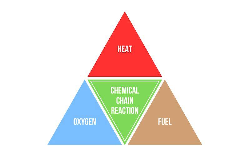
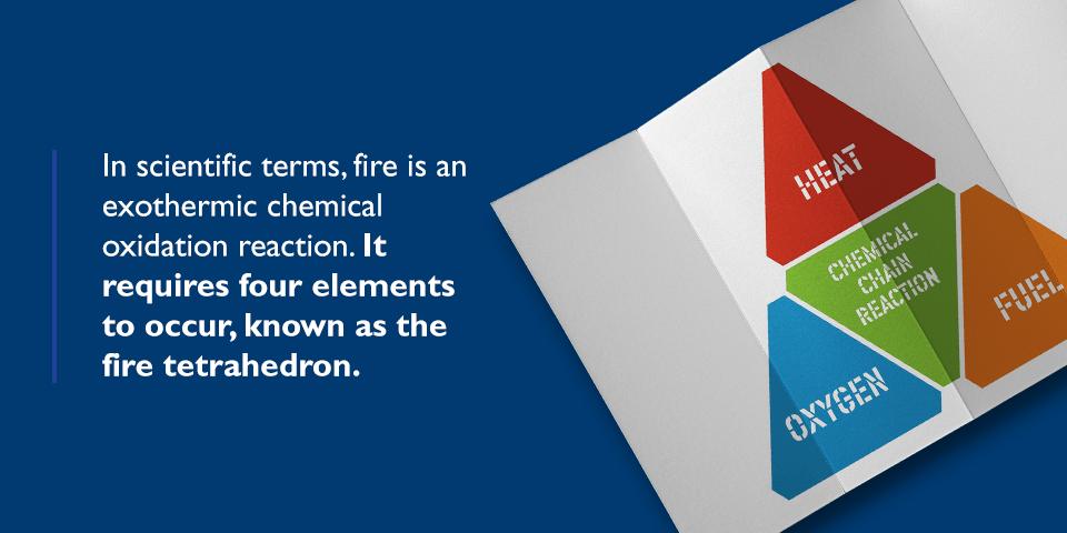
- a fire tetrahedron is a 3D object with four triangular sides (Fig. 1.5)
Fig. 1.5 Plane display of fire tetrahedron (https://hct-world.com/what -is-a-fire-tetrahedron/)
- each side is designated as fuel (1), oxygen (2), heat and energy (3), chain branching reaction (4)or chemical kinetics
- the role of temperature is important to initiating chain branching reaction
- the chain branching could be initiated by an increase in pressure, as would be the case for some explosives that are pressure sensitive
1.1.2 Combustion time and extent
- a temperature above normal air is needed to get combustion
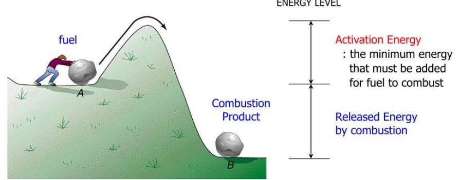
- the minimum energy needed to achieve combustion is called an activation energy (Fig. 1.6)
Fig. 1.6 Graphical explanation of activation energy (https://www.slideserve.com/bethany-king/activation-energy#google_vignette)
- for most hydrocarbons, the typical activation energy is about 160 kJ/mol
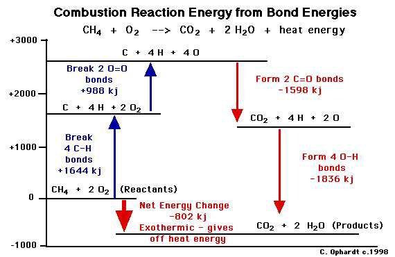
- energy conditions of methane combustion are displayed at Fig. 1.7
Fig. 1.7 Example of hydrocarbons combustion (https://www.processsensing.com/en -us/blog/combustion-control-cleaner-air.htm)
1.2 Combustion of substances of different states
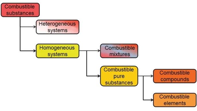
- combustion is a series of exothermic chemical reactions between substances, including a combustible reactant (in Fire Dynamics know as fuel – Fig. 1.8) and an oxidizer, usually air or oxygen
Fig. 1.8 Classification of combustible substances (fuels) (Schmierund, T. 2023)
- the heat release is accompanied in most cases by light in the form of glowing flame
- the efficiency of the combustion process and the temperature maintained are affected by a number of parameters, including those of the environment, construction and operation
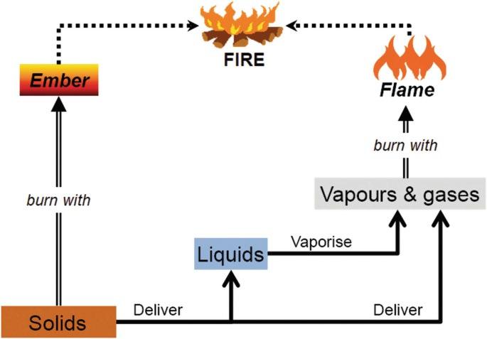
- however, fuel characteristics, e.g. states, are of major importance on combustion (Fig. 1.9)
Fig. 1.9 Combustion vs. state of agregation (Schmierund, T. 2023)
- a stream or jet of gaseous fuels can be ignited in air to give a flame, which is seen as the visible portion of the volume within which the oxidation process is occurring
- flame is a gas phase phenomenon and, clearly, flaming combustion of liquid and solid fuels must involve their conversion to gaseous form
1.2.1 Gases combustion
- the combustion of gaseous fuels may occur through one of four distinctive types of burning: 1. Diffusion flame, 2. Premixed flame, 3. Autoignitive reaction front, 4. Detonation
- the type of burning that occurs depend on the degree to which fuel and oxidizer are mixed prior to heating
- e.g. a diffusion flame is formed if the fuel and oxidizer separated initially, whereas a premixed flame is formed otherwise
- similarly, the type of burning also depends on the pressure – a detonation, e.g. is an autoignitive reaction front coupled to a strong shock wave giving its characteristic highpressure peak and high detonation velocity
1.2.1
Liquids combustion
- the combustion of a liquid fuel in an oxidizing atmosphere happens in the gas phase
- it is the vapour that burns, not liquid
- for burning liquids, this process is normally simple evaporative boiling at the surface (but liquids very high boiling points, ≥ 250 °C, may undergo some chemical decomposition, e.g. cooking oil)
- flash point of liquid fuel is the lowest temperature at which it can form an ignitable mix with air
- it is the minimum temperature at which there is enough evaporated fuel in the air to start combustion
1.2.3
Solids combustion
- the solids can burn with flame or with glowing and smouldering
- but for almost all solids, at conversion to gaseous form, a chemical decomposition or pyrolysis is necessary to yield products of sufficiently low molecular weight that can volatilize from the surface and enter the flame
- as this requires much more energy than simple evaporation, the surface temperature of a burning solid tends to be high (typically 400 °C)
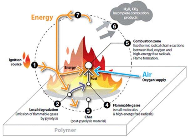
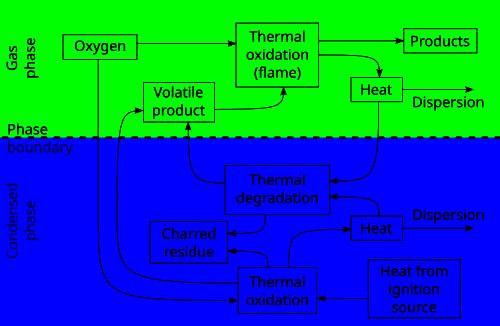
Fig. 1.10 A general scheme of polymer combustion (https://en.wikipedia.org/wiki/Combustion#/media/File:Disfig1.svg)
- the process of solid polymers combustion consists of three relatively distinct but overlapping phases (Fig. 1.10):
1) preheating phase, when the unburned fuel is heated up to its flash point and then fire point (flammable gases start being evolved in a process similar to dry distillation)
2) distillation phase or gaseous phase, when the mix of evolved flammable gases with oxygen is ignited (energy is produced in the form of heat and light, flames are often visible, heat transfer from the combustion to the solid maintains the evolution of flammable vapours)
3) charcoal phase or solid phase, when the output of flammable gases from the material is too low for the persistent presence of flame and the charred fuel does not burn rapidly and just glows and later only
1.3 Combustion in natural fires
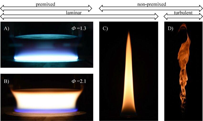
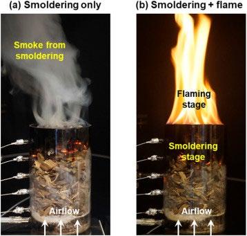
- natural fire processes can take different forms: 1. diffusion flames, 2. smouldering, 3. premixed flames
- these are all chemical reactions that produce relatively high temperatures
- flames occur as gases, the chemical reaction is solely it the gas phase
- smouldering involves the reaction of air with a solid, the chemical reaction occurs on the surface of the solid
- diffusion, or motion due to difference in concentration, is common to all flames
- a pure diffusion flame occurs when the fuel and oxygen diffuse from opposite sides of the reaction zone
- in the reaction zone, the fuel and oxygen are consumed, so their concentrations are zero there
- in a premixed flame, the fuel and oxygen (or air) are already well mixed before combustion
- the temperature of the mixture is low, but with a hot enough point in this mixture, a flame can emerge as a premixed flame
- the premixed flames are the ingredient of controlled combustion processes
- all diffusion flames are born from a premixed flame (Fig. 1.11)
- the term spontaneous combustion might be classed as a distinct fire process, but its occurrence results in either smoldering or a flame (Fig. 1.12)
- this is simply an ignition process that occurs naturally due to the energy generated by a chemical reaction
Fig. 1.11 Types of flame (Bauer, F. 2023)
Fig. 1.12 Types of fire process (Yuying, Ch. et al. 2022)
1.4 Combustion products
- the nature of the combustion products depends on the fuel composition and on the fire processes
- fire can be characterized as (1) premixed flame, (2) diffusion flame, (3) smouldering or surface oxidation
- chemical equation of methane burning in air: CH4 + 4 0 42 (0.21 O2 + 0.79 N2) → CO2 + 2 H2O + 4 ∙ 0 79 0 42 N2 eq.1.1
- for complete or ideal combustion, the products of eq. 1.1 are the most stable compounds: CO2 (carbon dioxide) and H2O (water)
- at combustion temperature, these species are gases, although the water could condense at cool surface
- we can compute for ever 16 g of CH4 (1 mol of CH4 has a mass of 16 g, 12 g for C and 1 g for each H) that we must have 4/0.42[0.21 · 32 + 0.79 · 28] or 274.7 g of air
- 1 g of air has about 0.23 g of O2 and 0.77 g N2
- when all of the methane and oxygen are completely consumed in the reaction, the ratio of this mass of fuel is called the (ideal) stochiometric air-to-fuel mass ratio (s): ���� = 247
- if more air is available, the process is termed overventilated or fuel lean
- for less air than required for stochiometric burning, the process is termed underventilated or fuel rich
- all of the oxygen in that air is reacted by the time the smoke leaves the flame
- in all cases, the nitrogen in the air is passive and remains constant, however, it will be hated as a result of the chemical reaction´s energy release
- typical fuels are hydrocarbons composed of H, C, they may also include O, N, Cl, F and Br
- the resultant combustion products depend on the process in air:
Process in air
Products
Ideal (stochiometric) CO2, H2O, N2, Cl2, F2, Br2
Overventilated CO2, H2O, some CO, soot, HCN, HCl, HF, HBr
Underventilated Same as above, but more CO, soot, hydrocarbons
Smouldering Same as above, but predominately CO
Evaporation, Pyrolysis Same as above, but more hydrocarbons
- the products of combustion depend on the process as well as on the fuel
- smouldering requires very little air to maintain, incomplete combustion resulting in a significant yield of CO
- the sufficient air available in a room fire to support flaming combustion
- if fire occurs in a closed room, the oxygen in air will be expended and the process becomes underventilated
- a small opening to the room will bring some air, but if the fuel generate is too great, the fire will remain underventilated
- extinction will generally occur when the oxygen feeding the fire is about 11% or less (less for higher room temperature)
- the parameter that quantitatively represents the over- and underventilation states is equivalence ratio
- equivalence ratio Φ is defined as the mass ratio of fuel (gas) available to air available times the stochiometric ratio s:
Φ = mass of fuel (gas) mass of air ∙���� eq. 1.3
- if Φ >1, the fire is underventilated, the decomposition products are not burned to completion
- if Φ <1, the fire is overventilated, there is sufficient air, the process will be complete
- all fires start with Φ <1 and with continued growth can reach Φ >1 states
1.4.1 Yields of combustion products
- the heat of combustion gives the energy release per unit mass of fuel burning
- yields give the mass production of each products species per unit mass of fuel burned
- the heat of combustion for a fire reaction is not the complete ideal value and must be measured, the yield of a species, too
- the yield of CO is defined as:
����CO = ����
where ����CO is the mass of CO produced and ���� is the mass of fuel burned
eq. 1.3
- if ����̇ is rate of burning and ����̇ CO is rate of CO mass produced, the CO yield is calculated as:
����CO = ������������ ���� eq. 1.4
- it is generally accepted that yields are fairly constant for a given fuel as long as Φ <1, but as the fire conditions becomes underventilated, the yields change
- fuel properties as a function of ventilation:
Conditions Underventilated
- in most cases, the yields (or negative yields, as in the consumption of oxygen) are slightly less then their ideal chemical reaction values for CO2, H2O and O2
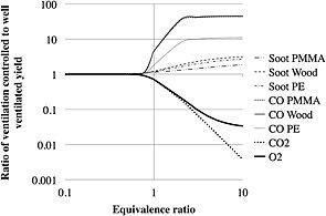
- the yields associated with the products of incomplete combustion (e.g. CO, soot) are relatively small, but these are the culprits that do the damage – CO can kill, HCl can corrode materials, soot can reduce visibility - underventilated values of yields for CO and H2 depend on Φ (Fig. 1.13)
Fig. 1.1 Yields of CO and soot at underventilated fires (Nilsson, M., Van Hees, P. 2014)
- CO yields are increased as the fire becomes underventilated (a state sometimes called ventilation limited in compartment fires)
- CO yields depend on fuel, but the yields of O2, soot, and CO2 are essentially fuel independent when plotted as ���������������������������������������������������������������� /
- for the wood CO yield of 0.2 g/g, this state would give a CO production rate of 33.4 g/s provided the burning rate of the wood can be maintained at 11 g/m2-s at the underventilated state
- the production rate of the polystyrene is 8.7 g/s for underventilated case
- the wood fire in the underventilated state has become more hazardous than the polystyrene fire with this higher production rate of CO
- the smouldering (at fire scenario of cotton or polyurethane foam mattress or sofa) produces CO yields of as high as 0.2 – 0.3 g/g
- these yields are comparable to the underventilations values in flaming for fuels, but the production rate in smouldering is much less than generally than of underventilated fuels
- a growing fire going through flashover to a ventilation-limited state suddenly produce toxic smoke
1.4.2 Concentration of combustion products
- the yields measure what is produced at the fire source
- the principal hazard of fire is the composition and associated concentration of harmful species in the smoke
- by the smoke we mean the gas stream that flows away from the fire continuing to mix with air and with having no further chemical reactions
- the amount of mixing with air determines the concentration of a particular species yielded in the flame
- we have a corresponding concentration at different points in the smoke
- the species concentration will decay as air is entrained into the smoke
- mass concentration is defined as:
2 Application of Physical Chemistry, Chemical Thermodynamics, and Combustion Kinetics
2.1 Heat transfer
- heat transfer causes the solid and liquid fuels to vaporise to produce gaseous fuel for the flame
- heat transfer is responsible for making the fire move over surfaces and through the forest
- it is the dominant factor in determining the fate of fire growth and the damage it can produce
2.1.1 Definition and heat transfer forms
- the study of energy is rooted in the subject of thermodynamics, the science that defines energy, heat, temperature and other properties
- all matter has energy (���� ) and mass (���� ), these are the essential properties of matter
- in the Einstein equation (Eq. 2.1), mass and energy are related and can be converted into each other ���� = ����∙���� 2
Eq. 2.1 where ���� is the speed of light
- the conservation of mass and energy is taken as a general truth
- as all matter possesses energy, it can take many forms
- the other forms of energy are discerned indirectly from the conservation of the energy in accordance with the First Law of Thermodynamics
- the industrial revolution allowed us to burn coal, heat a boiler to create steam, and move a piston to produce work
- in that process, several other forms of energy show up – chemical energy results from the oxidation of coal to products of combustion; heat transfer brings the energy to the boiler; the motion of the piston manifests as kinetic energy and is the converted into work
- energy is a state of matter from which we might extract work of obtain heat
- the kinetic energy of the moving atomic particles is called internal energy in thermodynamics
- the internal energy is a property of matter directly associated with the concept of temperature
- something that is “hot” has a relatively higher internal energy and temperature compared to that which is “cold”
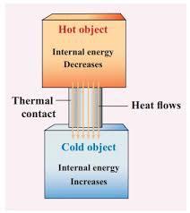
- heat (���� ) is defined as thermal energy in motion that travels from a “hot” to a “cold” region
Fig. 2.1 Heat transfer as energy exchange between hot and cold (https://www.brainkart.com/article/Solved-Example-Problems-for-Internal-Energy-%28U%29_36245/)
- an important quantity in heat transfer is heat flux (����̇ ,, ) – it is defined as the flow rate of heat per unit area it passes through
- there are three forms of heat transfer: conduction; radiation, convection
- the Fourier´s law of heat conduction – the rate of heat flow through matter is proportional to temperature difference divided by the distance separating those temperatures in the substance
- Planck´s quantum theory led to a theoretical basis for radiation heat transfer
- a convection heat transfer does not require a separate law to predict it – it applies specifically to conduction in a moving fluid
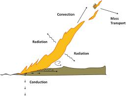
- at fire, the conduction occurs through wall (a solid matter), convention occurs at the wallflame or smoke interface, and radiation can be felt at the distance and to the wall
- also, radiation comes from the flame, smoke and hot wall
Fig. 2.2 Examples of heat transfer in fire (Castro Rego, F. et al. 2021)
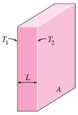
- heat conduction through a wall (����̇ ) is given as:
= ����∙����∙(����2 −����1 ) ���� (kJ·s-1 or kW)
Eq. 2.2
where ���� is thermal conductivity, ���� is the area through which the heat is transferred, ����1 and ����2 are the respective temperatures of the wall faces, ���� is the wall thickness
Fig. 2.3 Heat conduction through a wall (https://www.engineersedge.com/heat_transfer/conductive_heat_transfer_large_plane_13840.htm)
- a resistance factor (R-value, thermal resistance) is similarly used for heat conduction
- R-value is the reciprocal of ����∙ ���� ����
- heat conduction can play a role in propagating the fire
- substances can ignite due to conduction if they are in contact with a very hot body, also, corners will ignite before edges
- in general, heat transfer is unsteady, and it takes some time for the heat to penetrate through the substance, raising its temperature as the heat reaches a new depth
- if the surface of a material suddenly has an increase in temperature, the time for the temperature to increase at a distance ���� within the material is proportional to ���� 2 /����
- the thermal penetration time for 1% increase in temperature rise at ���� is approximately ���� 2 /12���� or to reach 50% of the increase is approximately ���� 2 /����
- thermal diffusivity is given by:
Eq. 2.3
where ���� is the density, and ���� is the specific heat
- the heat conduction propagation within the material is due to thermal diffusion or the diffusion of heat that excites neighbouring molecules
- as the internal energy of the molecules is raised by atomic vibration from their hotter neighbours, temperature increases and heat is propagated, somewhat like a wave effect
- if the material is a solid in a hot fluid such as air, the conduction between the air and the material needs to be computed
Table 2.1 Table of thermal properties of selected materials (Drysdale, D. 2011)
- in a moving fluid, the heat transfer from the fluid to a solid surface is called convection
- the heat flux to the wall (����̇ ,, ) is:
) Eq. 2.4 where ∆���� is temperature difference near the surface, ∆���� is the distance corresponding to the temperature difference, ℎ is the convective heat transfer coefficient
- we see that laminar flame is more powerful than its turbulent counterpart in convective heating
- the impact on fire hazard is mitigated as laminar flames quickly become turbulent after lengths about 0.3 m
- but the turbulent convective heat fluxes alone are not generally sufficient to sustain fire, this comes from the other way heat can be transferred – radiation
- all radiation is electromagnetic energy consisting of both electric and magnetic fields
- the radiation rays have both a frequency and a speed and can transverse within materials and through a vacuum or nothing
- the maximum possible output of radiation due to temperature is given by Planck is expressed in terms of heat flux ����̇ ,, as:
Eq. 2.5
where ���� is the object´s temperature (K) and ���� is the Stefan-Bolzmann constant given as 5.67 x 10⁻¹¹ kW·m-2·K-4
- this formula applies to a perfect radiator or blackbody, it gives the maximum radiation emitted at a given temperature
- surface effects and absorbing effects reduce this output
- the property that give the fraction of real output to the maximum value is called emissivity (���� )
- for solid and liquid surfaces, ���� is typically 0.8 ± 0.2 for fire radiation applications
- no radiation can pass through an opaque or non-transmitting surface
- radiation emitted from a transparent object emits radiation from within as well as its surfaces
- gases, smoke and flames can be transparent to radiation
- an effective emissivity of a uniform temperature transparent object such a flame depends on a thickness of a flame depends on the thickness of the flame
- for turbulent flames, the main source of radiation is the soot, soot particles radiate over the wavelength spectrum
- the effective emissivity of the smoke or flame can be estimated from the formula:
Eq. 2.6
where ���� is absorption coefficient of smoke or flame, ���� is its thickness
- the absorption coefficient is a property of the flame and is a measure of how easy it is for the radiation to penetrate the flame
- for turbulent flames, ���� typically ranges from 0.1 to 1.0 m-1
- for common fuel flames having a thickness of 1 – 2 m or more, the ���� would be nearly 1
- but for very larges fire, cold soot on its edges can obscure the flame and reduce the radiant heat flux to the surroundings from the higher temperature luminous regions of the flame
- the computation of radiant heat flux to a target is very important to assess potential damage and the possibility of a remote ignition from a fire
- we can use the formula:
2.7
where ���� is the combustion energy release rate of fire (W), �������� is the fraction of energy radiated relative to the total energy released, ���� >2���� , ���� is fire diameter
- �������� is not necessarily constant for a given fuel and generally varies from about 0.15 to 0.60 for low sooting fuels such as methane and high sooting flames, such as polystyrene, respectively:
Table 2.3 Typical radiative energy fractions �������� (Quitiere, J.G. 2017)
– 0.20 Butane, benzene, wood scribs 0.20 – 0.40
Hexane, gasoline, polystyrene 0.40 – 0.60
- �������� is more specific according to the diameter of fire:
Table 2.4 Specific radiation fraction of combustion energy for hydrocarbon pool fires showing dependence on diameter (Quitiere, J.G. 2017)
a The smaller-diameter fires were associated with higher radiative fractions
- the drop off radiative fraction is due to the cold soot swirling around the core of luminous flame for large fires, where the soot blocks the radiation and traps it
2.1.2 Heat flux and fire
- heat flux causes objects to get hot and possibly damaged or ignited
- the radiant heat flux from the Sun at the Earth´s surface is nearly 1 kW·m-2
-thresholds (minimum values of heat flux) to cause damage under fire conditions are follows:
Pain to bare skin: ≈ 2 kW·m-2
Burn to bare skin: ≈ 4 kW·m-2
Ignition of objects: ≈ 10 – 20 kW·m-2
- these threshold values will cause results indicated only after a “long” exposure of many seconds or minutes
- the time to cause damage to bare skin is about 30 seconds
- unfortunately, as flame radiation is most responsible, it is least predictable
- incident radiative heat fluxes to the floor in a door-vented room fire are the function of the upper layer smoke temperature
- this dependence can be also applied to measurements of total (convective plus radiative) heat flux to a ceiling target
- the smoke is the principal source of the heat flux to the floor
- if in room fires there is a distinct smoke layer and distinct central fire, flames and hot smoke will try to fill the room according to the fuel and air supply available
- the flames and smoke layer can reach 1200 °C or more
- as the flames will be thick (>1 m), their emissivity would be near 1
- in this case, the radiative heat flux could achieve 250 kW·m-2 in the room
- it is not uncommon to achieve heat flux levels 100-250 kW·m-2 in fully developed room fires
- turbulent convective heat transfer coefficient in room fires can typically range 5 - 50 W·m2·K-1
- the radiation is characterized by its maximum potential for a blackbody
- even at relatively low source temperatures, radiation is significant compared to natural convection (ℎ = 5 W·m-2·K-1)
- after about 500 °C, radiation truly becomes the dominant factor in heat transfer in fire
- measurements of the incident heat flux from flames to a surface can be useful in giving us a way to assess their fire hazard
- the heat flux will consist of the total of the convective and radiative components
- thin laminar flame will have a higher temperature than turbulent flames (about 2000 °C, over 1000 °C, respectively)
- convection will dominate these laminar flames
- large thick flames will be turbulent, and radiation will dominate them
- turbulent flames heat flux can range from 20 to 200 kW·m-2
- small laminar flames (as candle and lighter flames) can achieve heat fluxes 50 – 100 kW·m-2
2.2 Ignition
- the essence of fire growth is composed of ignition, flame spread, and burning rate
- ignition is the start of fire growth
- without ignition there would be no fire
2.2.1 Piloted ignition and autoignition
- the minimum condition for piloted ignition occurs at the lower flammable limit (LFL) – that concentration of fuel that allows propagation with a small sufficient heat source (pilot)
- this pilot can be an electric arc that possesses very high temperature or a small flame
- autoignition occurs without any pilot
- the fuel must still be within a specific concentration range, typically between the lower and upper flammability limits
- also, chemical kinetic processes must generate energy production to exceed the heat loss of the fuel gas-air mixtures
- the gaseous fuel evolves by heat transfer and mixes with air
- a pilot can cause ignition, or the hot surface of the solid might cause ignition
- in both cases, a sufficient fuel gas concentration must be generated
2.2.2 Liquid fuels ignition
- liquids generate fuel as vapor or gas
- this process continuously occurs on the surface
-if the liquid evaporates at a sufficient rate to form a concentration near the pilot source at the LFL to allow ignition
- the rate of evaporation is controlled by the liquid temperature
- escaping vapor creates a pressure that contributes to the total pressure of the atmosphere
- the vapor pressure is a strong function of temperature and increases sharply as the temperature rises
- the air above the liquid can enhance the transfer process over that of pure diffusion
- this effect due to airflow is called convection with respect now to mass transfer analogous to convection in heat transfer
- mixtures of fuels will evaporate depending on their components
- the more volatile components (higher vapor pressure) will evaporate first in hydrocarbon mixtures such as gasoline
- the more volatile component controlling ignition
- at piloted ignition, the surface concentration needs only to achieve the LFL
- at this concentration, the corresponding surface temperature is called the flashpoint (������������ )
- the pilot at LFL initiates a propagation of flame in the atmosphere above the liquid surface
- this flame is premixed flame
- it will propagate if the mixture is in the flammable range
- if the evaporation rate continues to increase, it is possible that a stable diffusion flame will form above the liquid surface
- the minimum liquid temperature to allow a stable diffusion flame is called the fire point –fire point is the minimum liquid surface temperature needed by the liquid to sustain a diffusion flame
- the boiling point is the temperature corresponding to when its vapor pressure equals to the exposed atmospheric pressure
- the boiling point can be assumed liquid surface temperature in a fire
- the process of piloted ignition has led from a premixed flame to a diffusion flame
- this process takes a little time
- the process of autoignition is a slightly different mechanism compared to pilot ignition
- autoignition occurs at a concentration generally between the upper (UFL) and the lower (LFL) flammability limits
Table 2.5 Critical temperatures for liquid fuels in °C (Babrauskas, V. 2003)
- autoignition is synonymous with spontaneous combustion or “self-ignition”
- this ignition inherently occurs due to an imbalance, triggered at the critical temperature, between the chemical energy production and the local heat loss in the gas
- the temperature at which this occurs is the autoignition temperature (AIT)
- AIT is mostly higher than the flashpoint and the boiling point
- under actual fire conditions, both autoignition and piloted ignition apply as competent scenarios
- however, the piloted ignition case is probably more predominant once a flame exists in accidental fires
- the vapor trail of a liquid fuel spill may travel some distance before finding a pilot source
2.2.3 Solid fuels ignition
- the ignition temperatures of solids are not precisely determined
- they depend on the decomposed fuel concentration, its components, and the way the solid is heated
- the formation of porous char may contribute to its variation
- the experimental results will give us some reasonable approximate values of ignition temperature
- solid fuels tend to be mostly polymers, either synthetic or natural (e.g. wood)
- when polyethylene is heated, it will start losing its structure melting at about 120 – 145 °C and will have a reported flashpoint of greater than 220 °C
- above 220 °C where ignition is possible, vapor must be generated
- the vapor is due to thermal decomposition (or pyrolysis – the production of vapor by heat from a decomposing solid)
- for some polymers, this vapor could ideally be the monomer, but mostly is not
- the vapor is likely a complex mixture of hydrocarbons
- the vapor pyrolysis products for wood will consists of many compounds
- some will condense in atmosphere as fine droplets (tars), displayed as white “smoke”
- wood, like some synthetic polymers, will not totally decompose to a vapour but will leave behind a carbonaceous porous char
- wood can exemplify the full range factors affecting the ignition of solids
- first, wood can contain absorbed water
- when the wood is heated to 100 °C, water vapor will diffuse both into and out of wood
- the released water vapor will increase the LFL of the air-fuel vapor mixture and retard ignition
- the trapped vapor in virgin wood and char, can lead to centres of locally high pressure that are usually relieved by cracks
- the formation of char on the surface can play the role of an insulator to heat conduction into the virgin wood
- the char is also a source of chemical energy as the char oxidizes from air diffusing to the surface
- while this oxidation will release insignificant energy at low temperatures, it could eventually lead to full-blown ignition to smouldering
- this solid-phase ignition might be termed glowing ignition as the surface will likely turn red (glowing ignition – start of smouldering at a high temperature to emit red light)
- the decomposition of wood is not like polyethylene, a melting solid
- wood thermally decomposes to char and vapour
- the vapour will be composed of a complex array of molecules from low volatility to heavy tars
- the mixture of vapours depends on the rate the wood is heated, so the LFL of the mixture will not be a precise constant for wood
- the LFL is theoretically dependent on the heat of combustion
- the heat of combustion for wood volatiles can range about 10 to 15 kJ·g-1
- for a solid, vaporization depends on the chemistry of pyrolysis, and it is a strong function of temperature
- as the wood nears a critical temperature, it will produce the needed vapor concentration for ignition
- this temperature at the surface to achieve the minimum concentration for piloted ignition or autoignition, we term as the ignition temperature (ignition temperature – effective surface temperature to cause ignition of emitted vapours)
- for piloted ignition and autoignition, the ignition depends on whether the wood was heated parallel or perpendicular to its grain
- the ignition temperatures are lower for parallel heating as it is easier for the volatiles to escape along the wood grain paths
- for both heating directions, the AIT is higher than that of piloted ignition
- the glowing ignition temperatures could only be noticed below 40 kW·m-2, as the time to ignite by flaming was too fast above 40 kW·m-2 to discriminate glowing before flaming
- the glowing temperature is always between piloted and AIT
- below 40 kW·m-2, the mechanism for autoignition is distinctly a transition from smouldering to flaming
- as the char layer builds up and further insulates, the surface temperature can rise to as much a 900 °C before flaming occurs
- the critical limits for piloted and glowing ignition appear to be about 10 kW·m-2 for ignition times approaching about 1 hour
- the time for flaming ignition of liquids and solids involves three steps:
- the first is predominately the longest – this is the time to heat to achieve sufficient vaporization
- the agent for heating could be radiant, convective, or conductive heating of the surface and could involve direct flame impingement
- the second and third steps are usually small
- the second step is the time for fuel vapor and air to mix into a flammable mixture
- the third steps the time it takes for the chemical reaction to release enough energy to be perceived as a flame
- for a pilot ignition this is generally less than a second
- for autoignition, this reaction time can be much longer
- the piloted ignition temperatures for solids to range from approximately 250 °C to 450 °C, with AIT exceeding 500 °C
- the key parameter in determining the ignition of solids (and liquids) is the surface temperature
- the temperature of thermally “thin” material is uniform throughout the thickness
- the criterion for thermally thin material is:
2.8 where ����̇ ���� .,, is the incident heat flux, ������������ is ignition temperature
- factor ����∙����∙���� is called thermal inertia, where ���� is density and ���� is specific heat
- time of ignition of thermally thick material can be calculated by:
Table 2.6 Typical ignition times of thick solids (Quitiere, J.G. 2017)
2.3 Flame spread
- ignition occurs in the fuel-gas air mixture
- following ignition, the next step in fire growth is surface flame spread
- the propagation of flame through the gas mixture is a form of flame spread
- surface flame spread requires certain conditions
2.3.1 Definitions and flame spread theory
- flame spread is a process in which the perimeter of the fire vaporization region grows
- it could even include the process of remote ignitions, if those ignition processes are continual
- in general, fire growth applies to the increase in the combustion process including surface flame spread, smouldering, and even the expanding fire front in premixed flame propagation
- in flame spread, and in fire growth, gravitational and wind effects are important
- the flow resulting from the fire´s buoyancy or the natural wind of the atmosphere can assist (wind-aided) or oppose (opposed-flow) flame spread
- the flame spread velocity is defined as the rate of motion for the perimeter position ��������
- the �������� denotes the extent of the pyrolysis or vaporization region
- the rate of combustion of the vaporizing fuel gases we define as the burning rate
- the concept of an ignition temperature is key to explaining flame spread
- the flame spread velocity ���� is obtained as:
where ���� is fuel density in kg·m-3, ���� is the fuel-specific heat in kJ·kg-1·K-1, ���� is the crosssectional area in m2, �������� is a fuel temperature beyond the range of the flame´s heat in °C
2.3.2 Fire spread on solid surfaces
- for spread over solid surfaces, the most significant heat transfer rate is at the surface over a length ��������
- heat flow rate is the product of heat flux and the surface area it acts
- therefore:
where ����̇ ,, is the flame forward heat flux, ���� is the width of the fuel
2.11
- the flow area is normal to the surface area, and it is designated as ���� or ����∙���� , where ���� is the fuel´s thickness
- if we substitute these formulas into Eq. 2.10, we obtain:
2.12
- for a thin solid (���� <2 mm), for we can write:
2.13
- since the thin solid ignition time is:
2.14
- this is a remarkably simple equation, as it says that the speed of the flame spread on the surface is the distance heated by the flame divided by the time to ignite that new material
- for a thick solid (greater than about 2 mm), the entire thickness ���� is not heated during the ignition time
- recall that the ignition time for a thick material is given by:
2.15
- flame spread in the direction of the airflow is generally referred to as wind-aided spread
- upward flame spread on the wall or flame spread under a ceiling in still air is also termed wind-aided
- in these cases, the wind is solely due to the buoyant flow caused by the fire itself
- the heat to make the flame move is mainly caused by the heat transfer from the extended luminous flame to the surface
- the flame length depends principally on the energy release rate of the fire driving it
- so, with increased burning, a longer flame and a higher speed result
- in general, upward or wind-aided flame spread depends on the nature of the igniting fire and the combustion properties of the wall
- if this upward flame spread scenario occurs in a room, the smoke layer will increase �������� causing the surface velocity to also increase as in downward or lateral spread
2.3.3 Fire spread through porous solid arrays
- flame spread can take place through porous solid fuels such as forest brush and debris
- even wind-aided flame spread through the arrays of urban dwelling can be considered in this class of flame spread
- in case of wood crib, the forward heat flux to cause spread is mainly within the array, not just at the outer surface
- there will be a flame above the porous material, but the principal factor controlling the spread is the heat transfer within
- a wind can increase both heating levels
- the spread rate is controlled by the fuel mass in the array characterized by the bulk density ��������
- the bulk density is the mass of the solid fuel divided by the volume of the entire array – the fuel and the air
- from the Eq. 2.10 for the array we obtain:
Eq. 2.16
where ����̇ ,, represents the overall heat flux within on top
- most often, the porous array is composed of cellulosic fuel matter, so that fixes the fuel properties
- however, moisture content is a big factor
- the forward heat flux in the array is a complex combination of radiation from the fuel elements and convection due to wind effects
- in wildland fires, there is used a model formulated by Rothermel
- wildland fires are very unique
- in many cases, they begin with a lightning strike that leads to smouldering of the forest ground covering dead brush
- this can lead to flaming much later, very likely due to a wind
- sometimes, the process is intentional, it is called “prescribed burning”
- the wind can push this early ground brush fire to a high level, and with severe conditions it can lead to burning the live forest material
- it can even get to the top of trees, this is called “crown fire”
- the embers generated as firebrands can travel well ahead of the fire front and cause new fires
- with the development of homes built into the forest, the phenomenon of the “urban wildland fire” has become a common event
- roughly, the heat flux and the thermal properties for forest materials are nearly constant
- the flame speed ���� , inversely depends primarily on �������� :
2.17
where ���� is in m·s-1, �������� is in kg·m-3, ���� is a constant of roughly 0.07 kg·m-2·s-1 for typical wildland fuels and 0.05 kg·m-2·s-1 for wood cribs of sticks up to 3 cm in diameter
- wind is a serious factor in forest and urban conflagration fire spread
- indeed, if the wind dies, the ability to contain these fires becomes more realistic
- for wind-aided flame spread through porous arrays we can calculate the flame speed ���� :
2.18
where ����∞ is the wind speed, and ���� is a constant ≈ 1 s·m-1
- the wind speed effect on the flame speed is approximated here as linear
- in reality, it can be more complex
2.3.4 Fire spread on liquids
- surface flame spread on liquid is similar to the mechanisms discussed for surface flame on solid
- the liquid differs in that motion can be induced in the liquid due to the spreading flame
- the fact that the surface of the liquid is hotter than the cooler liquid upstream leads to a buoyant flow that can influence the flame spread process
- also, the motion can be induced in the liquid by viscous or surface tension effects
- surface tension increases as the temperature decreases
- so, as one moves ahead of the flame on a liquid surface toward the cooler fluid, the surface tension increases and pulls the flame forward
- this surface tension effect would not be a significant mechanism in wind-aided spread on liquid pools because surface flame heat flux would dominate
- that is for pools of liquid that have a considerable depth
- a liquid spilled on a solid like a carpet, wood, or concrete floor would not possess the same flow effects
- the spread will be slower than a pool of liquid
- the liquid and porous solid would act like a composite, and the heat loss into the solid would mitigate the spread
- in still air, the radiation from the vertical flame leads to the highest spread rate
- as the air speed increases, the flame is blown over into a thin boundary layer flame that heats the fuel ahead by convection mostly
- over an air speed about 300 m·s-1, the flame is blown off
2.3.4 Fire spread through a dwelling
- distinct spread in a particular medium has been discussed
- it is far more complex to determine the fire spread rate through a series of rooms
- the overall fire growth rate can be measured in terms of the volume of the fire and the consistency and nature of the fuel in dwellings
- the heat transfer put out by the fire would increase with the volume of fire, so heat transfer could be taken as proportional to the fire volume as a first approximation
- this indicates that the rate of growth for the fire volume is proportional to the volume of the fire itself
- the constant of proportionality depends on the fuel and its configuration
- we would expect the density, specific heat, and ignition temperature of the fuel in the rooms to affect this constant
- for a given consistency of fuel in a series of rooms, the fire volume will double in a fixed time
- this fire doubling time for normal dwelling might range from 2 to 10 minutes
- the complex fire growth through a building can be classified into a quantitative format
2.3.5 Typical fire spread rates
- flame spread is a complicated phenomenon of fire growth
- the typical values of flame spread rates are given in Tab. 2.7
Wind -driven spread through forest debris or brush 1 – 30
Upward spread on thick solids
1 – 100
Horizontal spread on liquids 1 – 100
Premixed flames (laminar) 10 – 100
Premixed flames (detonation) ≈ 105
2.4 Burning rate and energy release rate
- the nature of the combustion products depends on the fuel composition and on the fire processes
2.4.1 Definitions and burning rate theory
- flame spread theory allows us to define the extent of the fire´s boundaries, and burning rate gives us the consumption of fuel within those boundaries
- burning rate is defined as the mass of solid or liquid fuel consumed per unit time
- by consumed, we mean it chemically reacts with oxygen
- in large structural fires, fuel may vaporize due to heating, but not immediately burn due to limited oxygen
- burning is combustion; fuel supply is that flow of burnable gases that potentially can make a flame
- therefore, one must distinguish between the mass loss rate of fuel in fire as fuel supplied and as the mass burned (fuel reacted with oxygen)
- two distinct quantities, mass loss rate or supply rate and burning rate, are considered synonymous
- if an alcohol burns, the heat from the flame will cause the liquid to evaporate and its mass loss
- the mass loss divided by the time to lose this mass is the mass loss rate (����̇ ), usually conveniently expressed in grams per second (g·s-1)
- here it is synonymous with burning rate as it is very likely that all the alcohol evaporated will be consumed in the flame, leaving products of combustion obviously behind
- some products of combustion can still be compounds of that might be capable of still reacting
- if the products do not go to their normal stable states (e.g. water vapor and carbon dioxide for hydrocarbons), the chemical reaction with oxygen is termed incomplete
- if we were to simply let the alcohol evaporate without ignition, the mass loss rate would not be synonymous with burning
- however, in this chapter for a material or object with free exchange of normal air, once ignited, the fuel supply rate and burning rate will be one and the same
- alcohols typically have their flashpoint less than normal air temperature, so a small flame near its surface will cause ignition
- once a diffusion flame forms over its surface, the surface temperature increases to nearly its boiling point
- the boiling point is the maximum temperature a pure liquid can reach when heated in normal atmospheric conditions
- but the temperature at the surface of a pure liquid cannot exceed its boiling point
- hence, the alcohol will start to burn at its flashpoint as a short duration premixed flame, then as the diffusion flame forms (fire point) and gets bigger, the liquid temperature will reach its boiling point and stay there
- during this increase, the rate of evaporation or the burning rate also increases accordingly
- this leads to an initial burning rate once ignited and then an increase until the rate becomes relatively steady
- this changing or unsteady burning is typical way fuels burn
- they will start low, then increase, and try to reach a steady state
- bur complex fuels, like wood that char, will first increase then decrease as the insulating char layer prevents the heat to get to virgin wood
2.4.2 Burning mass flux
- the rate of burning depends on the fuel properties, its orientation or configuration, and the area involved
- wood logs burn well together, but not alone
- a surface may burn easily on its underside, but not its topside
- the area of burning is controlled by its ignition and flame spread processes
- the rate of burning over that area may not be steady and may not be uniform
- the character of uniformity can be expressed by the intensity of burning over the surface
- this quantity is expressed as burning rate per unit area or mass burning flux ����̇ ,,
- it describes how each point of surface burns
- if we divide the fuel supply area into small surface regions, associating each surface with an ����̇ ,, , then the sum of ����̇ ,, times each corresponding surface area gives us the total rate of burning
- in the calculus, this would be refined as an integration of the mass flux over its area
- the local burning flux can vary
- it depicts a small laminar flame, like a candle size
- the flame at the edges will be near the surface and have a high heat flux
- as the flame is farthest away from the surface at this centre, the heat flux will drop
- but in the centre region, the flame could be thicker and may possess some radiation as well as convection
- this added radiation could make the heat flux increase
- in this way, the heat flux can have a bimodal distribution about the centre
- the heat of gasification ���� (kJ·g-1) can be regarded as a property of a liquid or solid fuel
- it is the energy needed to make the solid or liquid produce a vapour and is defined on a unit mass of the vapour, commonly given in kJ·g-1
- it is an exact thermodynamic property for liquid fuels and can be expressed with great accuracy
- for a liquid, it represents the sum of energy needed to evaporate the liquid at the surface, plus the energy needed to bring the liquid from its original temperature to its boiling point
- for a pure liquid, the vapour produced will be the same chemical as the liquid
- for a solid, the solid might melt than gasify, or simply pyrolyze (thermal decomposition) to a vapour
- both the melt and the vapour are rarely the same compound as the solid
- indeed, for charring solids, the original solid will transform in thermal decomposition to both char and vapour, simultaneously
- the heat of gasification is not an exact property for the solid because of its decomposition to new compounds
- the utility of the heat of gasification is that it can be used to predict the burning rate
- the heat of gasification is a precise property for a liquid, but an approximate for a solid
- a general predictive formula for mass burning rate per unit area, or mass burning flux, is given in terms of the heat of gasification:
Eq. 2.19 where ����̇ is the net heat flux to the fuel surface
- this formula applies exactly to the steady burning of a deep liquid pool
- for solids, it gives only an average result over the flaming period
- for shallow liquid pools or liquid fuels saturated into solids, the Eq. 2.19 overestimates the mass burning flux because of heat lost into the substrate of the liquid
- for something like gasoline poured on wood, the gasoline would burn off first
- the wood would assume the boiling point of the gasoline fuel components
- as the less volatile components of the gasoline begin to vaporize, the wood temperature would rise
- if sufficient heat transfer remains after the gasoline burns off, the wood might begin to vaporize and continue burn
- a burning liquid fuel with a low boiling point absorbed into the wood is likely to only cool a horizontal piece of wood (except at the edge of the flame where the wood is dry)
- the heat flux in Eq. 2.19 is the sum of heat from all possible sources
- in a fire the heat comes from the flame and the heated surroundings
- because the surface of the material burning is relatively hot, it will radiate heat to the surroundings
- the net heat flux (Eq. 2.19) for a material in a fire is composed of the flame above the surface (the incident flame heat flux, ����̇ �������������������� ,, ) and external radiant heat flux from hot surroundings (����̇ ������������ ,, )
- in addition, there is reradiation term due to the radiant energy emitted from the surface
- the reradiation flux (����̇ �������� ,, ) can be estimated as approximately the blackbody radiation from the vaporizing surface
- it is always greater than the critical flux for piloted ignition (CHF)
- the net heat flux for a fire condition is the algebraic sum of the heat flux components at the surface:
- in general, materials will not burn in a steady fashion even under fixed heating conditions
- at ignition, a material, will have a minimal mass flux
-once the flame occurs, additional heat will be applied, and the burning rate will increase
- the final steady burning rate value will take some seconds for a deep pool liquid, form melting solids it could take minutes, for charring solids, the process is more complex because of the increasing char layer that builds up
- however, as the char builds up, it forms an increasing insulating layer
- the char is porous as the vaporizing component has been depleted from the original material
- also, the char tends to be nearly all carbon and is effectively inert
- this inert increasing porous layer allows vapour from the virgin material to easily pass through it but diminishes the heat transfer by conduction from the flame to the virgin material
- this reduced heat transfer causes the burning rate to decrease
- as the char layer increase, less and less heat can be transferred to the virgin solid material for vaporization
- the flame will be sustained until the burning flux gets to a critically low value and extinguishes
- the flame elimination is followed by direct oxidation of the char
- smouldering then ensues, and the char slowing burns away
- once the char is depleted, flaming could resume it sufficient heating persist at the surface
- charring materials, such as heavy timber, likely burn it this repeated fashion in building fires
- the net heat flux depends on the flame: its size, orientation, soot concentration, and flow conditions
- typical mass burning fluxes for materials can range from about 1 to 100 g·m-2·s-1
- values below 1-2 g·m-2·s-1 usually led to extinguishment
- suppressing a fire by cooling with water can lead to extinguishment of the flame as the critical mass flux level is reached
2.4.3 Energy release rate
- the most important quantity related to fire is the energy release rate, or firepower measured in kilowatts (kW), and denoted by the symbol ����
- in much of the literature in fire, this has been called “heat release rate” denoted by HRR
- it, more than any other factor, represents the size of the fire and its potential for damage
- it is directly related to fire height
- the entire potential for fire growth and flashover in a room can be related to HRR
- the energy release rate is found through knowledge of the burning mass flux
- this burning flux times the area over which it acts give us the total burning rate (g·s-1)
- the heat of combustion is a property of the fuel that tells us how many kilojoules (kJ) of energy we get from each gram (g) of the fuel gases burned
- consequently, we can write:
Eq. 2.21 where ���� is the area involved in vaporization, �������� is the effective heat of combustion
- the term “effective” heat of combustion is used as opposed to the theoretical or complete heat of combustion
- the former applies during the flaming portion of fire, while the latter assumes all of the fuels burn to chemical species that can no longer still burn
- this is “complete” combustion
- the heat of combustion represents the chemical energy released per unit mass of vaporized fuel that is reacted
- typically, this heat of combustion for a wood (theoretical) would be approximately 19 kJ·g-1
- under fire conditions for wood, we would measure Δ�������� of approximately 12-15 kJ·g-1 for flaming period and approximately 30 kJ·g-1 for the smouldering phase of the char
- it should be appreciated that the grams (g) in kJ·g-1 is the mass of the fuel being reacted
- for example, if about 70% of the wood turns to fuel gas, and the remaining 30% burns as a char, then as energy must be conserved, using 14 kJ·g-1 for the heat of combustion of the fuel gas, and 30 kJ·g-1 for that in smouldering: (14 kJ·g-1 gas)·(0.7 gas/wood) + (30 kJ·g-1 char)·(0.3 char/wood) = 18.8 kJ·g-1 wood
- this shows how wood releases its energy in two stages – flaming and smouldering
- generally, both the production of char and the formation of incomplete products of combustion such as soot and carbon monoxide reduce the heat of combustion
- chemical additives (retardants) can also play a role here to reduce the heat of combustion
- the effective heats of combustion during flaming tend to be highest for gas and liquid fuels, and least for char formers
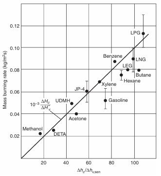
- an important parameter in assessing fire hazard is the ratio of �������� /����
- this has been termed the heat release parameter HRP
Table 2.8 Energy release properties of materials (Quitiere, J.G. 2017)
- the HRP values range from about 1 to 100, as materials move from char formers to liquid fuels
- materials that have a HRP lower than about 3, are not likely to burn since only a portion of the energy released is transferred back to fuel
- most of the energy is transported away in the buoyant flow, and some is lost to the surroundings by radiation
- the only practical way to determine the burning rate or energy release rate of item is by direct measurement
- this measurement depends on the manner of ignition, particularly for the initial fire growth over time
- the measurement device is called an “oxygen consumption calorimeter”
- the device works on the principle that the heat of combustion per unit mass of oxygen consumed is nearly a constant (13 kJ·g-1) for a wide range of ordinary fuel compounds
- the amount of burnable fuel or available energy is responsible for the duration of the fire
- the longer a fire burns, the more the structure can be heated
- at a critical temperature, the structure can fail
- table 2.9 gives some typical peak values of burning rate for real items along with very rough estimates of their peak energy rates
- these are presented to primarily illustrate the spectrum of fire power, not for precise generic use
- the fire growth rate depends on the ignition process; flame spread, which defines its perimeter; and the mass burning flux over the area involved
- for items of furniture and commodities, this complex process cannot be predicted by simple formulas
- however, each item, due to its composition and configuration, must have a characteristic growth time
- the growth rate approximately follows a relationship proportional to time squared
- considering the flame spread velocity as constant over time can provide an explanation for this time-squared behaviour
- then, the fire area would grow as ���� 2 (length is velocity times time, and area is related to length squared)
- alternatively, if the rate of fire growth depends on the fire itself, the growth rate would be exponential (���� ���� ), not ���� 2
- both of these growth rates have been suggested for the early fire growth
- but the t-squared relationship is simplest, and it seems to work well
- the empirical growth rate formula commonly used is:
= ����∙���� 2
2.22 where ���� is a constant associated with the item
- if ����1 is the characteristic time to reach 1 MW, then ���� =1 MW/����12 and
2.23
- this growth rate expression has been fitted to experimental data by ignoring the early incubation period where the growth process is establishing a foothold
- this incubation period is most likely due to spurious flame spread and the nature of the ignition process
- the precise incubation time is impossible to predict
- however, it can be significance if one is using the t-squared growth rate to estimate the time for detection
- detection may have occurred during the incubation growth period
- the ���� 2 relationship has proved useful for design of smoke control system as follows:
Table 2.10 Categories of growth time (Quitiere, J.G. 2017)
- these categories are only for rough guidance and perhaps standardization in design
- the data in Tab. 2.11 documented the burning of the items in a t-squared growth (represented with ���� ) to a steady maximum at ���������������� and followed by the t-squared decay (represented with �������� )
Table 2.11 HRR parameters for selected items (Natori, A. 2008)
- many other items can be categorized
- the method of ignition and the incubation period before the ���� 2 rate ensues are important factors in determining the precise growth rate
- the incubation period could be due to smouldering or simply the effect of a very slow initial spurious flame spread
2.5 Fire plumes
- all fires involve buoyancy, which sets the flow pattern and the nature of the flame
- this flow pattern directs the growth of the fire and sucks in the air supply
- it is also responsible for the characteristics of the smoke that departs the fire
- even under wind conditions, buoyancy plays a significant role in the fire´s behaviour
- when the fuel release is distributed on a horizontal surface (floor), this is commonly called a “pool” fire
- it is representative of a liquid fuel spill or even the horizontal portion of cushion on a chair
- such fires are mostly turbulent, and the release of fuel gas at the surface is at a relatively low velocity
- in a quiet atmosphere, the gases of the flame and hot smoke will rise vertically
- this rising flow stream is called a “plume” – more specially, a buoyant plume
- however, in a wind, the plume will bend according to its interaction with the wind, and eventually will follow the wind direction as the plume loses its buoyancy
2.5.1 Definitions and theory
- the mixing of fuel gases and air to form a flame cannot be appreciated with-out some knowledge of fluid dynamics
- the motion of a fluid (gas or liquid) is complex, and the equations that govern this flow are impossible to exactly solve
- computer models strive to do this
- they are referred to as computational fluid dynamics (CFD) models
- any CFD model has approximation and cannot accurately represent all aspects of flows
- while the use of computers, the user may lack an understanding of what is happening
- n contrast, equation development requires an understanding the fluid processes
- the physics of the problem must be translated into mathematics
- the relationship between velocity, gravity, and pressure is known as Bernoulli´s equation:
2 + ����∙����∙���� + ���� = costant along a streamline
Eq. 2.24 where ���� is the fluid density, ���� is its velocity, ���� is the symbol for the Earth´s gravitational force per unit fluid mass (9,81 N kg-1), ���� is the vertical height dimension, ���� is pressure (force per unit area – all fluids exert this pressure equally in all direction)
- the first term in Eq. 2.24 is the kinetic energy (KE) per unit volume of fluid, and the second term is the potential energy (PE) per unit volume
- the third term, pressure could be considered as work done on the fluid (force x distance) per unit volume
- pressure supplies the work needed to push the fluid
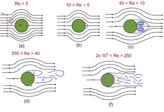
- a streamline is the path; a particle attached to the fluid would follow in a steady flow in around an object (Fig. 2.4)
- notice the smooth orderly flow (laminar) at first is followed by the chaotic flow (turbulent) downstream
Fig. 2.4 Flow past a circular cylinder at different Reynold´s number (Thangadurai, M. 2015)
- with this simple background of Bernoulli in fluid flow, jets and plumes can be examined as long as they are free of wall interference
- a jet is a flow where the initial velocity is so large that it dominates the streamline pattern of the flow
- a plume is a quieter flow due to the motion of a light (or hot) fluid in a heavier fluid (cold)
- this difference in density (or temperature) gives rise to an effective force called “buoyancy”
- a flow solely, or predominately, driven by its buoyancy, is called “plume” if it is in a free atmosphere, not confined by walls
- a chimney flow has confined walls
- at a chimney the temperature inside (TH) is higher than still air outside (TC)
- from experience, we know hot air rises, Bernoulli´s equation can explain this motion
- difference between the pressure at lower (p1) and higher (p2) height outside (also inside) the chimney is due to the weight of the cold heavy, stationary air outside the chimney
- the motion of hot gases out of the chimney can be expressed as:
�������� ∙����22
2 = (�������� −�������� ) ∙����∙����
Eq. 2.25 where �������� is a density of hot air, �������� is a density of cod air, ����2 is its velocity, ���� is the symbol for the Earth´s gravitational force per unit fluid mass (9,81 N·kg-1), ���� is the height between point of p2 and p1
- the term on the right-hand side is the buoyant force per unit volume
- it could be interpreted as the PE difference between the cold and hot air
- the difference in density has given rise the velocity (����2 ) out of the chimney
- while pressure overall will be nearly constant, differences in pressure will arise due to buoyancy
- more appropriately for fire-induced flows, these differences are better described in terms of temperature
- e.g., hot smoke properties can be related to cold smoke (mostly nitrogen for air and combustion products) by a relationship that required:
�������� ∙�������� = �������� ∙�������� Eq. 2.26
- in general, this is called an “equation of state”
- from this results, Eq. 2.25 can be rearranged as:
- the term in the denominator represents the buoyancy effect
2.27
- the quantity on the left-hand side of Eq. 2.27 has no dimensions since it is equal to a number 2
- it is a “dimensionless number” and it has the name Froude number (Fr)
- physically, it can be considered as the ratio of momentum to buoyant force
- for vertical turbulent plumes, in a statis atmosphere, with and without flames, this Froude number is found to be constant of about 1.5 ± 0.1 at all heights
2.5.2 Fire plumes and jets
- the laminar flames are very small, and their plume quickly becomes turbulent above the flame
- a fire plume is the buoyant column of flame and hot combustion products rising above the fuel source
- a buoyancy is the force that arise due to density differences
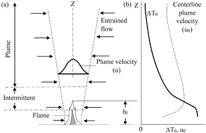
- because density is inversely proportional to temperature for gases, plume temperatures cause an upward force on the hot gases relative to the surrounding air (Fig. 2.5)
- if the hot plume gases cool to the local air temperature, the buoyant force would become zero, causing the plume to cease rising
- this condition is responsible for cigarette smoke stratifying in a room with a common slight rise in temperature as it moves up
- also, the plume from a forest fire will eventually even out in the atmosphere, and move only horizontally with the wind, as do clouds of water vapor
- if buoyancy is the only force responsible for the motion od the plume, its Froude number to be about 1.5
- if a flow can arise from a high-pressure tank, the initial “jet” velocity controls the flow, not the buoyancy
- in quantitative terms, this will occur if the initial Froude number is greater than 1.5
Fig. 2.5 Buoyancy and fire plumes (Qureshi, W. S. et al. 2018)
- a jet can be distinguished from a hot plume by how far it will travel horizontally before rising due its buoyancy
- the greater the horizontal distance, the stronger is the jet
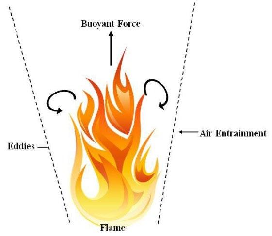
- as the hot gases rise in a buoyant plume, the colder air is induced to flow into the plume
- this flow process is called “entrainment” (Fig. 2.5)
- it occurs for two reasons – in purely laminar flows, the fluid friction drags the neighbouring fluid along, and it becomes part of jet or plume as it continues
- the rate of this entrainment flow is responsible for the flame height and the characteristics of the plume
- in general, flow can be laminar or turbulent
- laminar flow is smooth and orderly
- the candle flame is laminar, but its buoyant plume of heated gases becomes turbulent at roughly 30 cm (or less) above the flame
- within a turbulent flame, this high-frequency motion of the reaction zone can produce oscillations of hundreds of degrees at a fixed point
- as the buoyancy causes plume fluid to rise, its cooler edges are slowed and fall back down
- the large eddy turbulent effects present in all buoyant plumes can have a profound effect on flame height in combusting plumes
- although these turbulent flames are diffusion flames, but the diffusion mechanisms of bringing the fuel and oxygen together by concentration differences alone is now embedded within the turbulent flow
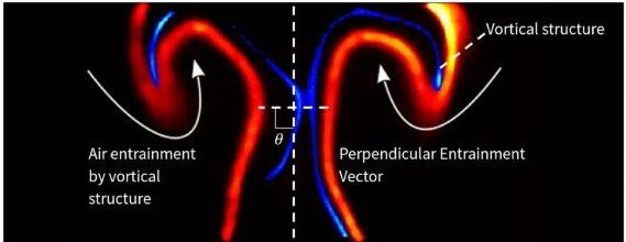
- the outer eddies produce a rising vortex between them (Fig. 2.6)
- as the burning eddy rises, it extends the flame until the fuel burns out
- a new eddy then carries the flame to this former height
- as a result, the flame height can fluctuate over a significant distance
Fig. 2.6 Air entrainment flow patterns into vortex (Xiao, T. et at. 2023)
- formulas for flame height usually give average results and do not account for the periodic “ripping off” of the flame
- the frequency of formation and departure of the outer eddies from the base of the plume (called vortex shedding) depends on the base diameter of the fire
-this vortex shedding frequency in Hertz for a fire diameter ���� in meters is approximately:
2.28
- a 10 cm fire would shed eddies about five times per second, but a large wildland fire of 100 m would form a vortex every 10 seconds
2.5.3 Flame height
- the symmetrical fires from horizontal fuel sources are called “pool fires”, representative of liquid fuel spills
- however, they can approximate other symmetric fuel shapes burning
- line fires and wall fires have somewhat different quantitative characteristics, tut are quantitatively similar in behaviour of pool fires
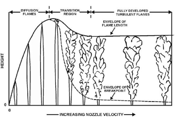
- for a gaseous fuel issuing from a fixed pipe diameter ���� at an exit velocity �������� , the ignited gases will result in an increasing laminar flame as �������� is increased (Fig. 2.7)
- as the exit velocity is increased, the flame is maintained as laminar up to a maximum length of nearly a distance of 200 diameters
- at higher velocities, the flow becomes turbulent, and the flame length becomes fixed for a given fuel and pipe diameter
- this phenomenon of a fixed turbulent flame height is a direct result of the entrainment process
Fig. 2.7 Flame height (length) for gaseous jets from a pipe of fixed diameter (Molkov, V., Saffers, J-B. 2013)
- the basis for the prediction of flame length is that the visible flame ends when all the fuel is burned
- because the fuel is supplied at the base, the end of the combustion process is controlled by how fast the air is entrained over the length of the fire plume (Fig. 2.5)
- the chemical reaction rate is fast compared to how fast air is supplied to meet the fuel, so the fuel reacts almost immediately when it encounters air
- this is why the entrainment of air controls the combustion process, and therefore the height of the flame
- the rate of air supplied (by mass) is equal to air density (�������� ) times entrainment velocity (�������� ) times the area through which the air was entrained
- this area can be approximated ����∙����∙�������� as since the jet does not expand so much
- the proportionally, we represent: Rate of mass entrained = ��������
2.29
where �������� is the density of the surrounding air, ���� is the pipe exit flow diameter, �������� is the flame length
- the mass rate of fuel supplied through the pipe is the density of fuel (�������� ) times the velocity of the fuel supplied () times the area of the pipe exit:
2.30
- these two mass flow rates must be at least in stoichiometric proportion in order for the air to burn all of the fuel
- for turbulent conditions it requires more air than needed for stochiometric combustion
- turbulence controls excess air, and it is not a function of the fuel type
- stoichiometric here implies that the stochiometric air-to fuel mass ratio (���� ) is that determined for a complete chemical reaction
- by replacing the fuel velocity with the entrainment velocity, from Eq. 2.29 and Eq. 2.30 we have:
- this result explains why the turbulent jet flame length becomes constant for a given fuel (having density �������� and stochiometric ratio ���� ) at a given diameter
- the “exit” velocity of fuel gases leaving the vaporizing solid or liquid fuel as they burn in still air are very low, not in range to be considered jet velocities
- this velocity is not responsible for the subsequent entrainment of air
- a simple explanation for the buoyant velocity is that the relative buoyant PE is converted into KE
- the relative PE per unit volume at height ���� under the gravitational acceleration ���� is: (�������� −����) ∙����∙���� Eq. 2.32 where ���� is plume gas density
- and the KE per unit volume is: ���� ∙ ���� 2 2 Eq. 2.33
- equating these energies gives the plume velocity as:
2.34
- or in terms of temperatures:
where ���� is plume gas temperature
- this velocity is approximately 4.5 m·s-1 for ���� =1 and (����−�������� ) �������� =1
- the fire plume velocity is more than 100 times the vaporization velocity
- measurements of flame height shown that the flame length is related to ���� ∗
- ���� ∗ is the ratio of combustion energy to nominal flow energy of the plume, it can also be interpreted as a length ratio
- an approximate demarcation between purely buoyant pool fire behaviour and where jet flames commence is approximately ���� ∗ ~104
- over a range of most natural fires, 0.5 ≤���� ∗ < 100, a relatively simple formula (from Heskestad) gives a good estimate of the average flame height: �������� =0.23 ����� 2 5 1.02 ���� Eq. 2.36 where ���� is in kilowatts, �������� and ���� are in meters
- recall that the flame height may fluctuate in time by a factor of 2 from its minimum to its maximum height, so Eq. 2.34 represents an average flame height
2.5.4 Fire plume temperatures
- the temperatures within a turbulent fire plume vary across the width of the plume from maximum at the centre to the air temperature at the edge
- we shall consider the centreline maximum temperature (����0 ) along the height (���� ) of a turbulent buoyant fire plume
- the variation with height depends on whether ���� is within combustion zone (����≤�������� ) or the non-combusting zone (���� > �������� ) (Fig. 2.8)
Fig. 2.8 a Schematic of different zones of a fire plume (flame (ℎ���� ~�������� ), intermittent, and plume) b Variation of excess temperature (����0 ) and centerline plume velocity (����0 ) with height (���� ) (Rangwala, A.S., Raghavan, V. 2022)
- over the combustible region, the flames regenerate ���� energy release rate and radiates a fraction (�������� ) of this energy away from the flame to the surroundings
- the energy that stays in the flame at the end of the combustion region at ���� = �������� is:
2.37
- the energy release rate is distributed over the flame length as the entrained air reacts with the fuel present
- once all the fuel is reacted at ���� = �������� , the energy rate (1 −�������� ) ∙���� remains constant after that throughout the non-combusting plume region
- at combustion zone the energy by combustion that stays in the fire plume by conservation of energy must be equal the thermal flow energy of the plume
- the flow energy rate of the plume (���� in kW) is represented by the mass flow rate times the thermal energy of plume:
(����−�������� )
2.38 where �������� is the specific heat of the plume gases, ����̇ is the mass flow rate of the plume gases
- the mass flow rate in the plume is nearly equal to the air entrainment rate, as the amount of fuel supplied is relatively small
- the energy released due to the combustion process is:
2.39
where ����̇ ���� is the mass rate of fuel reacted up to height ���� in g·s-1, ∆�������� is the heat of combustion in kJ·g-1
- it has been stated that more air than stoichiometrically required is entrained over the flame
- the turbulent mixing does not allow the available fuel to readily reacts with the entrained air
- ���� -times stoichiometric air is entrained and is needed to complete this fuel-lean combustion
- we can therefore write that the mass air entrainment rate is:
2.40
where ���� is the stoichiometric mass air-to-fuel ratio, ���� is the multiple stoichiometric air required due to inefficient mixing
- from Eq. 2.38, Eq. 2.39 and Eq. 2.40, it follows that the temperature rise in the fire plume is:
2.41
- ∆�������� /���� is approximately constant (2.9 kJ·g-1 air) for most all hydrocarbon fuels, kJ·g-1·K-1 for air, and it is experimentally fond, that ���� is approximately 9.6
- the average turbulent flame temperature rise (in °C) along the centerline of the fire plume is approximately (for air initially at 20 °C):
2.42
- this result demonstrates that the temperature within the combusting zone is not dependent on fuel type except for variation in ��������
- �������� can range from 0.15 to 0.60 for different fuels and may also depend on the scale of the pool fire (Tab. 2.3)
- large pool fires or very sooty fuels may have tendency to shroud the luminous flame in cooler black soot
- this shroud of soot can block the outgoing flame radiation, making �������� smaller and ���� larger
- this result has been found for large pool fires and indicates a maximum possible fire plume turbulent temperature of nearly 1500 °C
- for methane fires of 15 kW to 60 kW, the maximum (time-averaged) turbulent flame temperature of approximately 800 °C in which �������� was about 0.3
- Heskestad commonly associated a temperature rise of 500 °C as his measure of the average flame height
- importantly, turbulent flame plumes have a similarity in that, despite the value of the flame height, the fire plume´s temperature rise at the flames maximum tip at the end of the intermittent zone (Fig. 2.8) can be taken as about 300 °C
- gasoline and wood fires should show no temperature differences at the flame tip, but their flames lengths may be significantly different
- their flames can be stretched and squeezed, but their temperatures distribution are the same relatively to the combusting and non-combusting zones
2.5.5 Flame lengths and temperature calculation
- we can note that the flame length and flame height is approximately the same at symmetric flames and fire plumes
- in the case of asymmetric flames and fire plumes, we must differ the values of the flame length and flame height (Fig. 2.9)
Fig. 2.9 Main characteristics of asymmetric flame (https://fiercefires.weebly.com/how-to-measure-fires.html)
- next important characteristic of asymmetric flames is flame depth (Fig. 2.10)
- the experimental fire plume temperatures and the computed average flame height (using Eq. 2.36) of four fuels, where firepower was computed using Eq. 2.21 are follows:
Table 2.12 Flame heights and fire plume temperature at the top of flame of selected fuels, 1m in diameter (Quitiere, J.G. 2017)
- the wood result in Tab. 2.12 is indicative of a temperature in the continuous flame region, while the others are indicative of the peak flame height (���� = �������� )
- we have just seen that the turbulent flame temperature rise for moderate size pool fires (and it could be shown for other fire conditions) is nearly a constant maximum of approximately 800 °C and independent of fuel, particularly hydrocarbon
- literature values of adiabatic flame temperatures for hydrocarbon fuels burning in air typically range from 2000 °C to 2300 °C with measured laminar flame temperatures of 18002000 °C
- the adiabatic flame temperature is the maximum possible temperature that can be achieved for that combustion process of a fuel
- adiabatic means perfectly insulated, there is no heat loss from the reaction zone
- if we were capable of “ridding” on the fluctuating flame, we would measure temperatures in excess of 1300 °C and closer to the laminar flame temperatures
- the thermal threat of the turbulent flame is represented by the time-average temperature
- that is the temperature an object within or exposed to the turbulent flame would sense from the turbulent flame
- so, the time-average temperature is very important and is a measure of the damage potential of turbulent flame
- the flame height formula of the pool fire-like-flames can also apply to arrays
- others have considered different configurations
- these include a fire in the corner, against at wall, on a wall, and impinging on the ceiling
- the factor ���� ∗ enters into all these formulas
- formulas are couched in terms of the average flame length, and others differentiate between the continuous flame height and the peak height
- the results are in terms of ���� ∗ as:
- or alternatively in specific units for ���� in kW and ���� in m:
- Tab. 2.13 gives the values for �������� , ����
and
Table 2.13 Flame length parameters for Eq. 2.43 and 2.44 (Quitiere, J.G. 2017)
´ ���� in units according to kW and m
- there are other phenomena related to fire in the free atmosphere - a plume in the wind can lean over, and its length and angle can be computed as a function of ���� ∗ and the Froude number
- a wind can also induce a rotation in a plume
- this forms a fire whirl – a spinning plume (Fig. 2.11)
Fig. 2.11 (a): Fire whirls in Australia 2012,Chris Tangey, (b) Fire whirls from a 3-meter diameter pool in the Fire Laboratory for Accreditation of Modeling by Experiment, (c) The process of forming rotating columns of flame, (d) The laboratory fire whirl. (Zdhanova, A. et al. 2022)
- it can happen at the edges of large fire such as forest fires or fires of urban conflagrations
- the swirling motion at the base of that fuel increases the convective heat transfer
- anyone that has seen a fire whirl is amazed at how fast is spins its jump in height
- a large cylinder, cut in half along vertical lines, and displaced slightly around a centred liquid pool fire, admits a circulating flow to cause a whirl
- another atmospheric fire phenomenon is a fireball
- this is often seen in movies after a car careen off a cliff or following an “explosion”
- the fireball occurs due to a sudden release of gaseous or aerosol fuel that is ignited
- the core of fuel cannot burn all at once, it burns on its edges due a turbulent diffusion
- the increase in temperature of the combustion process gives buoyancy, and this carries the raw fuel and burning fuel upward like a burning sphere
- buoyancy distorts the sphere, and turbulence sets in
- just as the flame ends in a plume when the fuel burns out, the fireball stops in the same way
- as it rises, it gets bigger and higher, then it is gone
- the maximum diameter, its height, and its burning time are based on the original volume of fuel released
- this usually happens when there is a crash or breakage of a tank of gaseous or liquid fuel
- the fuel volume (�������� ) should be computed from the mass of fuel released divided by its density at the temperature and pressure of the air
- height of fireball can be calculated as:
(cm) = 12.7��������� (cm3 )�1/3
- maximum temperature can be calculated as:
- burn time can be calculated as:
- these simple formulas were derived from the theory and laboratory experiments
- they work quite well in large-scale events as they are based on sound physics
Theory of Combustion and Fire Dynamics
3 Fire
Dynamics in Fire Protection and Safety, and in Fire Suppression
This chapter is an introduction to fire dynamics. There are explained basic principles, role and terms of fire dynamics as an important part of fire science and base of fire extinguishing.
3.1 Position and role of fire dynamics
- fire is a dangerous force, leading to the destruction of property and death every year
- a proper understanding of the nature of fire is necessary for learning how to best control it during moments of crisis
- fire dynamics can provide a fire officer or a firefighter with means to understand how a fire will grow and spread within a structure and how best to control that grow
- fire dynamics is the field of study that encompasses how fire start, spread, develop and extinguish
- fire dynamics brings together several disciplines to better understand the nature of fire
- fire dynamics must incorporate the interaction of chemistry and material science and the engineering disciplines of fluid mechanics and heat transfer
- in addition, one must also consider the interactions of fire with structures, materials, and people to understand the fire dynamics of a given fire incident
- the goal of fire science is to determine how each aspect of fire´s circumstances impacts or influences its behaviour
- researchers have generated experimental results and computer models to explain how fire dynamics taken at the most basic level, the fire triangle (or fire tetrahedron) applies to the fireground
- learning more about fire dynamics is useful for following reasons:
a)it can help authoritative safety organizations learn more about the nature of fire and share this information with the public
b)it can stimulate conversations about safety protocol and how to handle fire
c) it can help manufacturers build more fire-resistant and fire-retardant building products
d)it helps businesses achieve safer working conditions, wiser fire emergency protocol and streamlined evacuation plants
- before you can take closer look at fire dynamics, you should understand the fundamentals of fire, definitions and basic terms in fire dynamics
Fig. 3.1 Fire tetrahedron (https://www.telgian.com/fire-dynamics/)
3.1.1 Definitions of basic terms in fire dynamics
- adiabatic flame temperature – the highest temperature achieved during a combustion process under adiabatic (no heat exchange with the surroundings) condition, where all the chemical energy of the fuel is converted into thermal energy
- autoignition temperature – the lowest temperature at which a substance (usually a fuel) will spontaneously ignite without an external ignition source, such as a flame or s spark
- backdraft – a sudden and violet explosion or fire that occurs when oxygen is reintroduced to a smouldering fire in a confined space, causing a rapid combustion
- BLEVE (boiling liquid expanding vapor explosion) – an explosion that occurs when a container holding a pressurized, flammable liquid rupture and releases the liquid, which rapidly vaporizes and ignites, creating a powerful explosion
- combustion – a chemical process in which a substance reacts with oxygen to produce heat, light, and usually, the release of gases, such as carbon dioxide and water vapor
- deflagration – a subsonic combustion process characterized by a relatively slow propagation of flame front through a fuel-air mixture
- detonation – a supersonic combustion process characterized by a shockwave front that rapidly compresses and ignites a fuel-air mixture, causing a rapid release of energy
- equivalence ratio – a ratio that compare the actual fuel-air mixture ratio in a combustion process to the stochiometric (chemically balanced) ratio required for complete combustion
- explosion ratio – the ratio of the actual fuel-air mixture to the stochiometric ratio, where an explosion is more likely to occur
- fire triangle – a fuel is surrounded by an oxidizer (oxygen), once it is exposed to a form of heat a chemical chain reaction is created, leading often to a visible flame
- fire – a rapid and uncontrolled chemical reaction involving the release of heat, light and gases, typically accompanied by flames
- flame – the visible, hot, glowing gas produced during combustion, consisting of burning gases and particulate matter
- flash fire – a sudden and intense fire caused by the ignition of flammable gases or vapours in the air, often without a preceding explosion
- flash point – the lowest temperature at which a liquid´s vapours can ignite when exposed to open flame or spark under specific test condition
- fire point – the temperature at which a liquid´s vapours sustain combustion once ignited, typically higher than the flash point
- pilot ignition – the initial ignition source, such as a spark or flame, that starts the combustion process in a controlled manner
- heat flux – the rate of heat transfer per unit area, typically measured in watts per square meter
- heat transfer – using the flames and products of combustion as a vessel; heat will transfer itself to its surrounding environment, recruiting additional fuels to heat and pyrolyze, compounding the problem
- ignition temperature – the minimum temperature at which a substance can ignite and sustain combustion in the presence of an ignition source
- ignition source – any heat source, spark, or open flame capable of ignition a flammable substance
- laminar flame speed – the speed at which a flame front propagates through a stationary fuel-air mixture under laminar (non-turbulent) condition
- flammability limits – the range of concentrations of a fuel in air within which combustion is possible; this includes the lower flammability limit (LFL) and upper flammability limit (UFL)
- pressure limit – the maximum pressure that can reached during a combustion or explosion event
- fire pyrolysis – the chemical decomposition of materials exposed to high temperatures in a fire, leading to the release of volatile compounds
- products of combustion – depending on a few variables, whenever a flame is present it will create heat, smoke, and pressure
- rapid-fire development – fire spread, and its heat release rate has reached its peak potential
- smouldering – a slow, low-temperature combustion process that occurs without an open flame, often characterized by the production of smoke and glowing embers
- spontaneous combustion – the ignition of a substance (usually organic) without an external heat source due to heat generated by chemical reactions within the material
- stages of fire – as the fire grows larger, it follows through a sequence of stages with key identifiable indicators; this is where firefighters can make informed decisions that can lead to suppression or rapid-fire spread
- thermal explosion – an explosion caused by a rapid increase in pressure due to a sudden release of energy from a thermal reaction
- thermal limit – the maximum temperature at which a material can be exposed without undergoing thermal degradation or ignition
3.1.2
Changes on the fireground
- while fire researchers were making gains on understanding fire dynamics in the laboratory, the hazards on the fireground and fire dynamics that accompanied them were changing
- e. g., the construction techniques and materials used to build and furnish a house, have changed significantly over the last 60 years (Fig. 3.1)
- engineered wood products have been incorporated into the design and construction of modern structures
Fig. 3.2 A comparison of fire development in the case of furnishing with natural and synthetic materials (Whitman, B. 2018)
- engineered wood joists and trusses enable longer spans and open areas (less compartmentation) for improved use of living space in homes
- since the 1970´s till 2020´s the median size of a single-family home has increased by more than 50%
- an increase the energy efficiency of houses, insulation has improved, walls are wrapped in plastic to limit infiltration of air and water, and multi-pane windows are now the norm
- when a fire occurs in an energy-efficient house, the insulation works to keep the heat and combustion products from the fire in the house
- it limits the amount of outside air that can be drown inside to complete fire triangle, provided that no doors or windows are open
- as a result, fires have less oxygen
- we can describe this in either or two ways, a ventilation-limited or a fuel-rich fire condition
- the objects and materials inside homes have changed as well
- a wide range of synthetic materials (polymers) are used in clothing, furniture, interior finish, and insulation
- the use of polyester, nylon, and polyurethane foam are commonplace in homes
- flexible polyurethane foam is one of the most common materials in upholstered furniture
- new materials, energy efficiencies, and construction methods have led to changes in the fire environment that a firefighter must face
3.1.3 Protective equipment
- firefighters use protective equipment to increase their safety and effectiveness on the fireground
- new materials (e.g. aramid fibres) and advances in technology often improved protection to the firefighter from thermal hazards and toxic gases
- aramids and polybenzimidazole have been in introduced that do not melt and have high resistance to ignition
- these materials are now in common use as part of firefighters´ protective clothing and equipment
- the evolution of the self-contained breathing apparatus, to include lighter materials, increase air supply, electronic monitoring
- warming devices has made working in a smoke-filled building safer
- continued developments in the fields of electronics and sensing have produced improvements in situational awareness for firefighters, mainly using the thermal imaging
3.1.4 Fire behaviour
- typically, firefighters have been taught about fire behaviour in structure as a simple graph (Fig. 3.3)
Fig. 3 3 Traditional idealized fire-behaviour graph showing a typical fuel-controlled fire (Madrzykowski, D. 2013)
- the idealized, qualitative graph shows that the fire begins with ignition
- the fire is then in the growth phase, where the heat-release rate increases until the fire is fully developed
- in a compartment fire, the transition from the growth stage to the fully developed stage may involve a flashover
- flashover is a transition in the development of a contained fire
- in flashover, surfaces exposed to thermal radiation from fire gases in excess of 600 °C reach ignition temperature more or ess simultaneously
- fire spreads rapidly through the compartment, with burning from floor to ceiling
- without an intervention, the fire transitions to the decay stage as the fuel is depleted
- this ideal curve is best suited for describing a fuel-controlled fire, in other words, a fire that has all of oxygen it needs to sustain the heat-generating chemical reaction with the fuel
- the peak heat-release rate is limited by the amount of fuel available for combustion
- the decay stage is typically related to the reduced amount of fuel available for burning
- free-burn fires mean fires with no compartmentation effects (Fig. 3.4)
Fig. 3.4 Heat-release rate time history form sofa “free burns” (Madrzykowski, D. 2013)
- for a typical, residential-scale roof with a doorway approximately 0.9 m wide by 2.0 m high, the minimum heat-release rate required to flashover the room is about 2,000 kW
- for a sofa fire in a compartment with an open doorway, which allows for the continuous flow of oxygen from the outside of the compartment to the fire – in each case, the free burn and the open-room burn, the fuel-controlled pattern pertains: basic growth, fully developed, and decay
- an idealized curve of a ventilation-controlled case (Fig. 3.5) – the fire begins with ignition and the growth stage
Fig. 3.3 Idealized fire -behaviour graph showing a typical ventilation-controlled fire (Madrzykowski, D. 2013)
- as the high-heat-of combustion fuels burn in the nearly air-tight house, fire begins a decay stage due to limited availability of oxygen for the combustion process
- as the available oxygen decreases, the heat-release rate of the fire decreases, along with the gas temperatures in house
- if a door or a window is opened while the fire is still burning, although at a reduced level, and if additional fuel is available, the introduction of outside air can result in a rapid increase in the heat-release rate of the fire and may enable enough energy generation to flashover the room
- this transition has been referred to as a ventilation-induced flashover
- once enough oxygen has been made available to allow the fire to reach the fully developed stage, it may become fuel-controlled again until decay or until suppression by the fire department
3.1.5 Flow path
- flow path is another concept central to fire dynamics in structures
- the flow path is the volume between an inlet and an exhaust that allows the movement of heat and smoke from a higher-pressure area within the fire area towards lower-pressure areas accessible via doors, windows, and other openings
- depending on its configuration, a structure can have several flow paths
- operations conducted in the flow path, between where the fire is and where the fire wants to go, places firefighters at significant risk due to the increased flow of fire, heat, and smoke toward their position
- this risk is true for natural-ventilation case with or without wind
- in cases with the potential for wind to affect the heat-release rate and the movement of the fire, it is important to keep the wind at your back to attack the fire from the upwind side
- working against a wind driven fire is a worst-case scenario
-a wind-driven flow path occurs when accelerated wind activity both controls the flow path and dramatically increases its oxygen supply (Fig. 3.6)
- if met head-on with wind driven activity, an alternative route of entry must be found, even if that means the back side of the structure
- often there is the difference between life or death depend on whether it is or not a glass window broke
- in effect, death occurred due to a change in ventilation, while firefighters worked in a space between the fire and lower-pressure area where the fire wanted to go – the path of least resistance
- flow path is also a term used to identify the direction in which oxygen, heat, and smoke travel once a compartment is opened
- structural firefighting requires a compartment to be opened, and every opened compartment will have a flow path
- whether it be through a door, a window, or a roof, a flow path and its effects will be present and must be handled appropriately
- the objective of this phase is to understand the effects of flow path and how to control them
- when a structure fire has a single opening, it will have a bidirectional flow path (Fig. 3.7)
- the bidirectional flow path occurs when the interior and exterior atmospheres compete to travel through the same opening simultaneously
- from the exterior, oxygen is drawn into the compartment, occupying the bottom half of the opening because of its cooler temperature
- simultaneously, heated products of combustion exit from the interior, occupying the openings top half
- visually, this creates a neutral plane, separating the two environments as the opening midpoint
Fig. 3.6 Wind driven fire (Whitman, B. 2018)
- the hazard with a bidirectional flow path occurs when the flow path occupies the same opening that personnel must enter
- as personnel enter and advance, they are met head-on with the flow paths exhaust point, subjecting crew to high temperatures and volatile gasses
- if the exhaust is excessively hot and violent, crew must emphasize a slow pace of advancement with aggressive water application
- by placing a fixed stream towards the compartment´s highest levels, gas contraction will take place, removing both heat and pressure until ventilation tactics are ready
- a coordinated vertical ventilation is a situation like this would create unidirectional flow path that would greatly improve condition for advancement
- a unidirectional flow path occurs whenever a compartment has two or more openings
- the separate atmospheres no longer complete to travel through the same opening, allowing the intake and exhaust points of the structure exist at separate locations (Fig. 3.8)
Fig. 3.7 A single ventilation opening is established, creating a bidirectional flow path (Whitman, B. 2018)
Fig. 3.8 A second opening is created, slowly transitioning the flow path (Whitman, B. 2018)
- visually, unidirectional flow paths are easy to identify
- if on opening is roughly 100% inlet or 100% exhaust, there is a corresponding opening elsewhere to pair with (Fig. 3.9)
Fig. 3.9 With two ventilation openings present, a unidirectional flow path is created (Whitman, B. 2018)
- because heat and gasses rise (Fig. 3.10), exhaust points will typically be dictated by height, causing the high-levelled opening to be the exhaust while the lower-levelled opening becomes the inlet
- when dealing with openings of similar height, pressure, not height, dictates their locations
- the closer an opening is to the seat of the fire, the higher amount of heat and pressure it is subjected to, forcing it to become an exhaust and thus, leaving the further opening to become that intake
3.10 Smoke and fire production increases due to increased supply of oxygen (Whitman, B. 2018)
- when the different forms of flow path have been identified, the next step is to understand how some of our most common tactics create them
- personnel should make it second nature to think about current and expected flow paths whenever performing these tactics
Fig.
- forcible entry immediately creates a flow path
- fortunately, most methods of forcible entry leave the breached opening intact, allowing the flexibility to close opening and create controlled flow path
- because of its timing on-scene, the opportunity for forcible entry typically arises prior to hose lines being ready
- if so, forcible entry should still be achieved, however, with an emphasis towards the entryway staying closed until hose lines are in place
- the most reliable way to manage the flow path is with good door control
- door control means limiting the size of an opening by closing door as much as possible and whenever possible
- however, balancing the need for door control and hose advancement can be difficult when personnel are limited
- ideally, the first-in engine company should be relieved from door control as soon as support arrives, by doing so, hose advancement can remain aggressive while still limiting the environment oxygen
- when support is limited, door control should remain the focus until advancement requires further assistance
- at no point should door control take priority over water application
- the most important aspect of vertical ventilation is good coordination with the interior suppression crew
- if vertical ventilation is done prematurely, a flow path is created, accelerating conditions prior to personnel going interior (Fig. 3.11)
- to make matters worse, what separates vertical ventilation from other tactics is its inability to closed once created, this is referred to as an uncontrolled flow path
- vertical ventilation is only effective if it is achieved simultaneously with meaningful water application
- if done correctly and properly coordinated, the unidirectional flow path relieves the products of combustion while hose streams combat the heat
- if vertical ventilation is applied without water application, fire behaviour will always increase and drastically worsen interior conditions
3.11 Vertical ventilation – firefighter creating a unidirectional flow path (Whitman, B. 2018)
- hydraulic ventilation is a tactic that should be applied immediately once the fire has been knocked down
- firefighters should find an exhaust point and position their nozzle 1 – 3 m away from it
- once the hose line is opened, a straight stream can exit the opening and slowly turn into a 60° fog pattern without fully encompassing it (Fig. 3.12)
Fig. 3.12 After knockdown, a straight stream is flown through opening – minimal entrainment of air exits the window (Whitman, B. 2018)
- by doing so, the 60° fog pattern creates air entrainment, a component to our hose stream that uses nozzle pressure to physically pull interior environment out the exhaust point, aiding in visibility for the primary search (Fig. 3.13)
Fig.
- what makes this option superior to other forms of ventilation is that the nozzle is already in the hands of interior personnel, making the transition of knockdown to ventilation seamless
- bypassing the time for communication and coordination, crews can immediately exhaust the toxic gases (Fig. 3.14)
3.1.6 Operating above the fire
- fire operations above a fire in a wood-framed structure with an unprotected engineeredwood floor assembly bring together several of the risk factors
- in a basement fire, the exposed wood-floor assembly is a sufficient and well-placed fuel load that can support rapid-fire growth and the transition through flashover if there is enough ventilation available
- due to the excellent insulation capabilities of wood-based subflooring and floor coverings, even firefighters with thermal imagers might be unaware that a post-flashover fire burns
Fig. 3.13 Firefighter adjusts the nozzle to a fog pattern – firefighter fully encompasses the opening, blocking the ability to exhaust (Whitman, B. 2018)
Fig. 3.14 Fog pattern is flown through the opening, leaving the bordering spaces unblocked – maximum entrainment of air exiting the window (Whitman, B. 2018)
below them and that the structural integrity of floor on which they are standing is compromised until they fall through it
- the thermal imager can only sense increased temperature due to heat flow through the floor and floor coverings
- during basement fire experiments (Fig. 3.15), there has measured temperatures more than 800 °C on the lower (fire side) on the floor assembly while the temperature on the upper side of the flooring was 100 °C or less just prior to the collapse of the floor
Fig. 3.15 Temperature time-history curves comparing the temperature of the fire-compartment (lower) side of oriented strand board (OSB) subflooring and the temperature of the upper-level room side of the OSB (approximately 18 mm thick)
(Madrzykowski, D. 2013)
- in basement fires, current practice calls for firefighters to fight their way down the stairs to suppress the fire
- if the firefighters survive crawling on a floor assembly that may be burning underneath them, they will find the stairway and place themselves in the flow path between the fire in the basement (high temperature/high pressure area) and the open front door (exhaust vent to lower temperature/lower pressure area)
- in other words, the firefighters are trying to work their way down the chimney of a burning fireplace
- this is a high-hazard location with the potential for high convective heat transfer (Fig. 3.16)
Fig. 3.16 The flow path of high-momentum fire gases going up the stairs can be seen in the NISN Fire Dynamic Simulator of the Cherry Road fire (the firefighter victims were all working in the room at the top of the stairs) (Madrzykowski, D. 2013)
- for these cases the application of water from the exterior through a basement window or door is suitable
- this exterior offensive tactic is known by many names: early water, blitz attack, resetting the fire, softening the target
- applying water through the window into the fire area quickly mitigated the hazard (Fig. 3.17)
Fig. 3.17 The impact of flowing a hose stream into a basement fire through the basement window at 820 L/min for 60 seconds (Madrzykowski, D. 2013)
- many of the fire-dynamic applications on the fireground presented above earlier were intuitive, but some were not
- while many in the fire service recognized some of the increased hazards in residential fires individually, few understood the synergy between the synthetic fuel loads, reduced compartmentation, and the lightweight and energy-efficient construction
- fire-test results have shown that the synthetic-fuel fire is more reactive to the introduction of oxygen than are fires fuelled by wood and cotton
- the synthetic-fuel fires are less forgiving in terms of how quickly conditions on the fireground can change
- the thermal conditions generated by a fire can exceed the material limitations of firefighter´s personal protective equipment by more than 500 °C
- of course, human thermal limitations are significantly lower than that
- fire department leaders need to consider revising their tactics to improve firefighter safety and effectiveness
- controlling the heat side of the triangle through early suppression from the exterior must be considered, even if these tactics go against current practice
- firefighters at all levels need to be armed with improved knowledge about fire dynamics, their workplace, and the equipment that they use to protect themselves
- some of tactical options: 1. keep the wind at your back; 2. stay upwind of the fire; 3. identify and control potential flow path by managing ventilation (i.e. open doors and windows)
- an exterior direct attack on the fire from the burned side may be the best option
- using the safest and most effective tactics possible is good not only for firefighters but also for victims trapped in the building
- applying the knowledge of the flow path in real-time is an even taller task to accomplish
- despite all its different forms and subtle nuances, the entire danger of flow path really boils down to two key principles: 1. avoiding the exhaust point; 2. Limiting the fire´s oxygen
- so long that these two principles are handled properly, flow paths will heavily contribute to a successful fire attack
- regardless of the reason, wind driven, or simply choosing the wrong entry – avoid the flow path exhaust point
- at well-developed exhaust point, the chance to be over-run with fire behaviour drastically increases
- if the exhaust point cannot be redirected, communicate your findings, and perform a 360°size-up to find an alternative means of entry
- if no enter point is available, a risk-assessment must be performed
- if entry at the exhaust point must happen, then the pace of advancement must be slowed down with a heavy emphasis towards door control and water application
- with a well-developed fire, the best way to avoid an exhaust point is to create a unidirectional flow path, up and away from personnel
- however, doing so comes at the cost of your inlet growing, increasing the supply of oxygen
- if the increased oxygen is left uncontrolled, fire growth will quickly escalate
- the solution falls back zo fire triangle
- the triangles component of oxygen is strengthening, in which in turn, strengthens heat
- we combat this issue by de-stabilizing both oxygen and heat simultaneously
- as a flow path becomes unidirectional, address the component of oxygen via door control while combating the component of heat through aggressive water application
- now is the time to embrace the knowledge of fire dynamics based on chemistry and physics, employ a size-up of every fire scene, and then choose the fire-fighting tactics and task assignments on that assessment
3.2 Aspects of fire dynamics
- fire dynamics is a broad and extensive field of research that has years of experiments and scientific studies behind it
- there are five the most fundamental aspects:
1.heat release rate
2.fire ignition
3.room fire dynamics
4.flame spread
5.smoke
3.2.1 Fire and heat
- the following two concepts contribute to a fire´s combustion:
a) the materials – different materials have a varying effect on the fire´s characteristics; the material used as fuel will release a certain amount of energy per unit weight as it burns
b) the speed of released energy – it describes how quickly energy releases from the material
- you should also understand the difference between “heat of combustion” and “heat release rate”
- the material as fuel influences the heat it gives off
- wood and paper have the lowest heat of combustion, which means it takes less heat for wood to catch on fire
- fuels such as plastic or gasoline have much higher heat of combustion, meaning it makes more heat for a fire to begin consuming them
- heat release rate has to do with the heat a material gives off when it is burning
- wood may have a low heat of combustion, but its heat release rate is high
- this makes wood (something that requires little heat to ignite) an extremely dangerous material when burning
- a fire´s heat release rate is a much important factor than its heat of combustion because it can have drastic effects on surrounding materials and people
- starting a campfire is a good example of heat release rate in action
- trying to start a campfire with a single log is tough work
- instead, your best bet is to chop up the log into smaller pieces, or kindling
- each tiny piece of kindling has a high heat release rate, which raises the surrounding kindling´s temperature, making the whole bunch easier to light
- imagine if you ground a log into sawdust and scattered it throughout the air
- each tiny piece of sawdust would have such a high heat release rate that a single ignition could result in an explosion as each speck combusted at once
- it is clear to see that the configuration of the fuel influences a fire´s heat release rate
- more available surface area leads to a higher heat release rate, causing fires to burn faster and hotter
3.2.2 Fire ignition
- ignition refers to the moment a material catches on fire
- it occurs when a material´s surface gives off enough combustible vapours at an ignitable range
- for some materials, like flammable liquids or gases, these vapours can exist at standard ambient temperatures
- that is why smoking cigarettes is illegal while filling up your gas tank
- the burning ash can ignite the vapour of gasoline, which could then spread to the liquid gasoline itself
- solid flammable materials need the application of a heat source to their surface to start giving off ignitable vapours
- the necessary amount of energy for this release to occur differs among materials
- pyrolysis is the process in which solid materials transform into a gas, and it is a key part of the ignition process for these solid materials
- a process called “charring” Can affect the ignition of solid fuels as it influences the transfer of heat
- fire chairs its fuel as it consumes it, creating a carbon-based, solid deposit where uncharted fuel used to be
- as the fire rages on, char becomes ash – the familiar deposit leftover in a campfire after the fire has used up all fuel
- solids that resist charring leave nothing behind after the fire consumes and decomposes them
3.2.3 Room fire dynamics
- surroundings of fire will affect its intensity and growth rate – this is especially true with indoor fires
- room fire dynamics takes a closer look at how fires behave in rooms based on various factors
- a burning Christmas tree in room creates a hot gas fire plume extending upward the ceiling, called “ceiling jet” (Fig. 3.18)
- the fire then spreads from that point above the Christmas tree to the rest of the ceiling
- before long, the fire reaches the room´s walls
- the smoke and fire from the ceiling jet then accumulate and descend to the floor, engulfing the whole room in flames
- through a process known as s “flashover”, the heat from the ceiling radiates to the rest of the room, leading to the combustion of all flammable materials nearby
- this can lead to fire spreading at a rapid rate
- the smoke and fire then begin spreading through any openings, cracks or doorways in the room, looking for more fuel and oxygen to consume
- the smoke and toxic gases that spread throughout a building pose a threat to anyone inside
- breathing these harsh substances can cause damage to the lungs, causing serious injury or even death
- studying fire dynamics shows that smoke travels away from the source of the fire, making an area dangerous even if the fire is raging in a separate room
- if a room is airtight, the fire could use all the oxygen in the room and begin to diminish after reaching its developing stage
- in the most fortunate circumstances, this could happen before the fire engulfs the entire room
- this poses a severe threat it oxygenated air can enter the space through a newly opened door or window
- the reintroduction of oxygen could cause a “flashback”, which is a fireball formed from large amounts of fuel bursting into heavy flames in a single moment
Fig. 3.18 Ceiling jet
(Owen, Q. 2018)
3.2.4 Flame spread
- flame spread is the movement of fire across the surface of a liquid or solid fuel source
- this is possible due to rising temperature of the fuel source, influenced by the flame
- as the temperature of the fuel increase, the fire can travel farther across it
- this forms a cyclical relationship
- as the fire heats up the fuel, it can more easily consume it
- if there is more fire present, there will be more heat, allowing for a greater flame spread rate
- slow-burning fuels like plastics have a slower flame spread than fast-burning fuels like paper or gasoline
- the fastest-burning fuel sources need little external energy for combustion, allowing the flames to travel at sometimes frightening rate
- if you have ever seen an area covered in gasoline light up into flames, then you understand the sheer speed at which flames can spread across fast-burning fuel sources
Fig. 3.19 Flame spread on wooden flooring
Fig. 3.20 Horizontal flame spread on thermoplastic material (Jiang, L. et al. 2013)
3.2.5 Smoke
- smoke is one of the most dangerous aspects of a fire and can cause death before the fie even reaches a person´s location
- understanding the behaviour of smoke is a crucial part of fire dynamics
- smoke has different appearances depending on the current stage of the fire from which it originates
- light smoke often appears during the smouldering combustion stage of a fire
- dark, black smoke is characteristic of full combustion and the presence of flames (Fig. 3.21)
Fig. 3.21 Fire smoke colour interpretation (https://smokedsystem.com/wp-content/uploads/2024/04/1709637546833.png)
- it is important that the smoke layer above the flames has a high amount of heat transfer
- this is due to the high heat release rate of soot present in the flames
- smoke can absorb and scatter light, making it of great interest to the safety and protection industry
- learning more about how smoke affects light helps manufactures make safer, better products
- these include products with the following characteristics:
i) visibility – soke has potential to obscure the visibility od exist for people trying to escape a fire, this makes fire sprinkler systems important in reducing the amount of smoke that could block someone´s line of sight
ii) smoke detection – people rely on fire alarms and smoke detectors to warn them of a sire in their building, a good alarm system can provide the warning needed for everyone to get to safety before fire and smoke spreads
iii)the ability for light to shine through the smoke – quality emergency exit lights are crucial for helping people find a way out of burning building, emergency lights should emit their own light, and they should be bright and bold enough to cut through a fire´s dense smoke
3.3 Water application
- modern fuel loads have created an environment more volatile than ever before
- the volatility of today´s fires doesn´t come from them burning hotter, it comes from their heat release rate, which allows temperature to accelerate faster than ever before
- this only further highlights the importance to applying water as quickly as possible
3.3.1
Exterior water application
- exterior water application is a use of exterior water streams, a transitional attack
- the tactic of transitional attack does not replace an interior attack, nor does it relegate personnel exclusively to exterior operations
- a transitional attack is an offensive fire attack made from the exterior of a structure
- the transitional attack´s sole objective is to improve interior conditions prior to entering
- crews can begin cooling the environment as soon as possible, contracting the super-heated gases and “resetting the clock” for flashover
- as crews knock back the fire, the hose lines repositioning is then prepared to support a seamless transition, concluding this tactic with an interior advancement to chieve a full knockdown
- the opportunity to employ a transitional attack comes down to two scenarios, categorized as: 1. an action of need; 2. an action of opportunity
- when interior conditions are unsafe to enter, an action of need is presented
- as we analyse our buildings and conduct a size-up, we may see conditions on the verge of a hostile fire event
- whether it be the direct point of entry or from a distant window, firefighters can take this opportunity to cool their environment as opposed to entering and facing these conditions head-on
- another action of need is when a rescue is being performed
- while rescue efforts are conducted, exterior crews can flow water into or around the area of rescue
- by doing so, conditions will drastically improve, resulting in gas contraction, lowered temperature, and a more tenable environment for victims awaiting extraction
- in an action of opportunity, we imagine being the first in nozzle firefighter at a fully involved single family residence
- near the front door, smoke and fire are spewing out of a compromised window
- you are masked up, nozzle in hand, hose line charged, ready to go
- you have the opportunity to flow water into the structure and improve the conditions until the delay is resolved, at which point you´d immediately go interior to aggressively attack the fire
- the most effective way to perform a transitional attack is based on water mapping
- it begins by identifying the most effective angle for our water stream to be positioned (Fig. 3.22)
–
- personnel positioned themselves as close as possible to be affected opening
- then, water streams were directed with a steep angle towards the ceiling, just clearing the openings header (Fig. 3.23)
Fig. 3.22 Improper technique: firefighter flows water into a window with a shallow angle
proper technique: close proximity (Whitman, B. 2018)
Fig. 3.23 Improper technique: a shallow angle causes the stream to only make contact with backside of the compartment
– proper technique: a steep angle allows the stream to make contact immediately, dispersing water along the entire compartment (Whitman, B. 2018)
- as the water´s pressure contacted the ceiling, it continued to slide along its path until it collided with the corresponding walls, creating a sprinkler-like effect, and providing the greatest amount of surface area coverage
- when the angle was decreased, the hose stream would not a significantly lower amount of surface area
- this was consistent regardless of nozzle type or pattern
- when water is applied effectively, interior conditions improve drastically not just for the initial compartment but for the structure as a whole, allowing the quick onset of gas contraction to cascade and cool the adjacent rooms
Fig. 3.24 Improper technique: rapid stream movement pressurizes the compartment, pushing heat and gases further into the structure
– proper technique: nozzle movement stays fixed, minimizing air entrainment, and allowing window to self-exhaust (Whitman, B. 2018)
3.3.2 Interior water application
- it is important to identify what our objective is when making an interior water application
- the underlying objective is to protect any survivable spaces where victims may be finding refuge
- because victims are not afforded respiratory or heat protection like we are, fire personnel must utilize their hose line with a more deliberate application
- choosing to not just extinguish the fire, but to aggressively create a more tenable atmosphere for victims, until a rescue is performed
- when it comes to interior operations, the question then arises “what exactly is impeding our ability to extinguish the fire and protect survivable space?”
- the answer is: the hat release rate (HRR), pressure, and re-growth
- pyrolysis drives the HRR
- combustion or not, pyrolysis occurs across all surfaces during a structure fire, providing a constant supply of gases to expand and ignite, increasing the HRR
- as the heat transfers to adjacent surfaces, the cycle repeats itself, creating the problem where the rate of release outpaces our rate of absorption
- the next problem is pressure
- as pressure expands to a large enough volume, it starts to control the environments circulation
- this creates a problem, as the products of combustion move freely throughout the structure, surfaces, victims, and personnel become saturated with its contents
- the last problem is re-growth
- during the advanced stages of fire, interruptions in water flow can allow the HRR to reestablish itself
- this creates a problem, as breaks in water flow become prolonged and frequent, the seat of fire is allowed the time to pyrolyze, creating rebounding effect that prolongs extinguishment
- if these three components exist freely, the fire is dictating the outcome
- if heat, pressure, and re-growth are problems, then our methods of cooling, air entrainment, and advancement are the solution
- however, results can be inconsistent when personnel are simply “putting the wet stuff on the red stuff” and flow without purpose
- instead, personnel must utilize their hose line to its greatest efficiency
- to combat the HRR, personnel must apply water rapidly in a slow and methodical manner
- creating the rapid contraction of gases, breaking the cycle of pyrolysis, and creating a pace where we can absorb heat at a faster rate than it is generated
- aiding in the battle against pressure, personnel must use air entrainment to control their environment, directing the products of combustion out and away from themselves
- to combat re-growth, personnel must advance their hose line with a relentless pace of water application, preventing any chance for the fire to re-establish itself
- when these components are applied, were now dictating outcome
- when we open the nozzle, highly pressurize water flows out
- as the water flows outward, it pulls air along with it a lot of air
- this is called air entrainment and the quantity we generate can be increased and/or limited depending on how we operate the nozzle
- when we create rapid movement with the hose stream or widen the nozzle pattern, entrainment is increased significantly, creating up to 340,000 L·min-1, surpassing the L·min-1 of a gas-powered ram-fan
- comparatively, when a straight stream is flowing in a fixed position, entrainment is severely limited, generating as little as 14,000 L·min-1
- this is an important concept to understand
- it highlights the nozzles capacity to act as both a fan water stream simultaneously
- due to the environments pressure directing heat and toxic gases towards firefighters
- it is incumbent on personnel to use air entrainment to redirect and control their environment (Fig. 3.25)
Fig. 3.25 Fixed stream is flown, creating minimal air entrainment – Opposite side ventilation opening shows no movement of smoke (Whitman, B. 2018)
- because for patterns dramatically limit the streams distance and penetration, a rapidly moving straight stream is the option of choice
- this is best achieved by moving the nozzle in an “O” (Fig. 3.26) or “inverted U” (Fig. 3.27) pattern with a straight stream
- this creates a pressure-front that “seals off” the entire span of the compartment and directs the products of combustion away from victims and personnel, towards the exhaust point (Fig. 3.28)
3.28 Both options create air entrainment. Pressurized smoke exits the opposite side ventilation opening (Whitman, B. 2018)
Fig. 3.26 Option 1: O-Pattern, nozzle moves in a rapid circular motion (Whitman, B. 2018)
Fig. 3.27 Option 2: Inverted U nozzle moves from left to right – nozzle movement continues from right to left and repeats itself (Whitman, B. 2018)
Fig.
- not only does this action improve visibility but the products of combustion become less rich as they exhaust, decreasing the atmospheres volatility
- normally, this tactic could be achieved by use of a fan
- however, the coordination between increased ventilation ad water application would have to be precise to avoid the possibility of pressurized oxygen feeding the fire without water application
- because these two components are married through our hose line, the environment is ventilated and cooled simultaneously
- after identifying the structures state of ventilation, personnel must choose the appropriate way to operate the nozzle
- with the option to apply water with a fixed stream or with nozzle movement, personnel can apply water in a methodical manner to control their environment
- when opening the nozzle, firefighters must identify if a ventilation opening is present, as this will dictate how the hose stream should be flown
- because a moving hose stream creates air entrainment, the thermal layering, as well as the products of combustion, will pressurize and travel away from the interior crew
- whether it be a window, door, or hole in the roof, a ventilation opening must be established to allow the products of combustion to exhaust from the area of high concentration (the interior) to the area of low concentration (the exterior)
- if a ventilation opening is not present, the resulting pressure will have no outlet to escape
- this leads to a back-pressured event that will disrupt the thermal layering, causing hightemperature gases to bank towards personnel, or worse, travel to the structure uninvolved areas
- when met in this situation, a nozzle flowing in a fixed position of choice
- when conditions warrant a fixed stream, the emphasis must be on our hose streams angle
- since we cannot incorporate air entrainment, the battle of pressure must be controlled through gas contraction
- this is accomplished by applying water towards the highest point of the compartment
- by doing so, were addressing the area where the hottest gases exist and have the greatest potential to combust
- as water coats the ceiling, it contracts and absorbs the hot gases, leaving its space unoccupied
- this allows the next layer of gases to rise and once again occupy the ceiling space for our hose stream to absorb
- as this process repeats itself, the absorption of each layer creates a visible “lift” in smoke (Fig. 3.29, Fig. 3.30)
Fig. 3.29 Thermal layering of gases prior to water application (Whitman, B. 2018)
Fig. 3.30 Thermal layering absorbed after water application, creating a “lift” (Whitman, B. 2018)
- this lift supports a firefighter´s visibility to observe the layout of the structure and locate the source of the fire
-when conditions warrant a moving hose stream, firefighters have the option of ether “O” or “Inverted U” pattern
- by doing so, not only are we creating a pressure front but were also cooling the environment in an efficient manner
- both options start with opening the nozzle towards the ceiling, addressing the superheated gases for both contraction and absorption
- however, the compartments other surfaces are still pyrolyzing and must be addressed
- this is where the rest or our stream´s application has its effect
- with either pattern you choose, the stream moves back-and-forth from the ceiling to the walls in a methodical manner
- this allows the water to coat all other surfaces, absorbing heat and halting pyrolysis
- regardless of the technique, their principals of advancement fall into two categories: 1. Shutdown and Move, 2. Flow and Move
-a choosing the proper method will differ in how the environment is effected around and ahead of the suppression crew
- Shutdown and Move involves shutting down the hoseline to facilitate the advancing crew’s movement
- when encountering the earlier stages of fire, such as the incipient and early moments of the growth stage, a shutdown and move is appropriate
- however, if applied inappropriately, such as the advanced stages of fire, interior conditions can become difficult to extinguish
- this is due to the hose stream being shut down for a prolonged period of time, allowing temperatures to rebound to their original state
- when this method was applied inappropriately, when the nozzle was shutdown periodically re-growth occurred
- to make matters wors, conditions often developed with interior crews unable to notice its development
- the early stages of re-growth were often over the head of the advancing crew and because of their structural protective gear
- then crews were unable to feel any changes in their environment until re-growth reached a more pronounced state
- Flow and Move is suitable when met with extreme conditions
- then the emphasis must be made to keep an open hose line during advancement
- as long as the hose line is flowing, the environment is reacting to our tactics, creating a constant cycle of cooling and contraction
- when interruptions occur, requiring the hose line to shut down, gases are afforded the time to rebound and expand
- this allows the fire to take back control, creating an environment where we are now the ones having to react
- every second that water is flowing stops that, creating conditions where our rate of water flow smothers the heat release rate (HRR)
- the relentless and methodical water application towards the room origin can drop temperature from 1,200 °C to 200 °C within 15 seconds
- closing statement: the number one priority of the fire service is saving lives
- if a victim cannot exit a building, we are counting on them to seek a survival space for shelter, waiting for a rescue to be formed
- those victims are counting on us to protect that survivable space
- how we intend to protect that space is with the fire services most reliable tool, the hoseline
- as our only mitigating resource, a successful fire attack starts and stops with a well-trained firefighter operating the nozzle with purpose
- our training and knowledge with fie dynamics provides us the knowledge to assess, identify, and predict our fire´s environment
Theory of Combustion and Fire Dynamics
4 Dynamics of Internal Fire Development
4.1 Compartment fires introduction
- fire in a compartment involves the containment of smoke and the potential for the fire to spread beyond the compartment
- small fires can transport smoke over great distances
- large fires can be affected by the compartment – enhanced due to thermal feedback (increased heat transfer) and diminished due to oxygen vitiation (decreased air flow to the fire)
- the motion of smoke and air in these fires is mainly due to buoyant effects as a result of the increased temperatures
- typically, the forced conditioned air supply in a building is secondary to this buoyant flow
- the transition grom an object burning in a room to the fire suddenly growing to it biggest possible size
- smouldering fires will be briefly discussed
4.2 Stages of fire development
- fire in a compartment is initially unaffected by the compartment conditions
- but as the oxygen is reduced in the compartment and the compartment temperature rises, the compartment conditions play a role in the behaviour of the fire
- the stages of fire development in a compartment could be depicted in terms of temperature and time (Fig. 4.1) are following:
Fig. 4.1 Stages of fire in a compartment (Khan, A. 2021)
- the fire usually develops from a single item (1. Developing, growth)
- then grows rapidly and usually involves others (2. Flashover)
- progresses to the biggest fire the compartment and its ventilation can allow (3. Fully developed)
- and, once extinguished, the process ends (4. Cooling stage)
- Fig. 4.2 a, Fig. 4.2 b show stages of experimental compartment fire:
4.2 a Average temperature variation in experiment (curve at top left corner shows ideal development) (Wu, K. 2023)
4.2.1 Developing fire
- following ignition, the fire grows on an item and may also involve other items
- the oxygen concentration and compartment temperatures are not much different than normal air
- the fire behaves as if it is burning in the open air for most of this period
- however, for some fuels, the smoke can have very limited visibility (10 cm) and significant CO content (0.3 %)
Fig.
Fig. 4.2 b Sequence images of the fire development process during the experiment (Wu, K. 2023)
- the smoke layer in the room would be above mid-height
4.2.2 Flashover
- flashover marks a dramatic increase in fire conditions due to the confinement of room
- flashover applies to this period of change
Fig. 4.3 Diagram of compartment fire (a) pre-flashover stage, and (b) flashover phenomena (Zhang., J.Y. 2008)
- it can be caused by several situation (A – B):
-A. the rapid ignition, burning rate, and flame spread of materials due to increasing heat flux arising from the heated room (Fig. 4.4)
- this is commonly called backdraft by the fire service and others but can be regarded as a type of flashover
- as a premixed flame can move rapidly through the gas, this event can release a lot of energy in a short time
- as a result, the pressure in the compartment can increase, causing a large pulse of flame and possible structural and glass failures
- at A., the beginning and end of flashover, it is transition that can occur over seconds or minutes
- it is due to an instability
- it is much like an ignition process
- in ignition, first there is fuel and air and there is a flame
- in flashover, first there is a small fire and then there is a big fire
- for flashover, the instability is caused by the firepower suddenly exceeding the heat loss and energy flow rates from the compartment
- this imbalance results in a sharp temperature increase in the smoke of the compartment
- flashover will cause the fire to reach its fully developed state
- all of the fuel gases may not be able to burn within the room because the air supply is limited
- flames will occur near the origin or seek out available air supply locations
- the flames will not fill the room, but the smoke layer will descend near the floor
Fig. 4.6 (a) Flashover representation as a transition phase in the fire standard curve before the fully developed fire stage in an enclosure (b) Ventilation induced flashover representation (Cortés, D. 2020)
- flashover terminated when all of the oxygen in consumed or when flames cover all the available fuel in the room
- the former state is termed ventilation-limited, and latter state is called a fuel-controlled fire
- then flashover marks a transition in which the fire development was previously dominated by the fuel materials and subsequently is primarily controlled by the ventilations indicative of the room and building geometry
4.2.3 Fully developed
- this stage occurs after flashover
- if there is sufficient air (fuel controlled), flames fully encompass the room, with the likelihood of flames extending from windows and doors
- if sufficient air is only available to the room, the fire is ventilation limited
- a ventilation-limited fire can define as one in which the smoke leaving the room has a concentration of 0 % oxygen – all of the oxygen is reacted within the room
- when the ventilation-limited condition occurs, the production of CO, smoke, and energy are at their highest values
- more fuel will be generated by heat in the room than can be burned inside
- its equivalence ratio ∅ is greater than or equal to value 1
- all of the fuel is involved to its maximum potential
Fig. 4.7 Fuel-controlled and ventilation-controlled fire (Ingason, H. et al. 2024)
- for a ventilation-limited fire, the room´s energy release rate is established by the available air supply rate
- most compartments and buildings become ventilation limited at this fully developed stage, as there is always enough fuel in typical furnished rooms compared to ventilation (Fig. 4.8)
Fig. 4.8 Fire behaviour in the compartment (https://www.linkedin.com/posts/imran-haider-nfpa-certified-fire-officer-cfps%C2%AE-cfi-hazmat-opt4b16ab206_classification-fire-classify-activity-7243683724125519872-4Vxy)
- typical ranges of values for CO, smoke, visibility, an equivalence ratio, were computed for various fuels contained in the room
- the firepower was selected to match the stage of the fire, with a 500 °C criterion for the onset of flashover
- the fully developed state marks the point where the structure becomes vulnerable
- heat flux conditions in the room can reach as high as 270 kW·m-2
- this corresponds to as smoke temperature of 1200 °C that may occur in large compartment fires
- but in special objects, such as tunnels, the temperatures can reach the value about 14001500 °C, such fire conditions would have had extremely high heat fluxes
4.2 4 Cooling stage
- the fire will eventually extinguish as it runs out of fuel in the fully developed stage
- the compartment surfaces and objects remain hot
- out-gassing still remains, as fire die to smouldering
- the toxic conditions during this period remain hazardous and can be of harm to firefighters
Fig. 4.9 Comparison between gas, compartment linings surface temperatures, structural element surface temperature, net heat flux, and fire heat release rate during the various phases of a post-flashover compartment fire (DiNenno, J.P. 2022)
- most significantly the cooling stage is still a factor in heating the structure
- this is especially true for steel reinforcing rods in concrete
- while the steel rods may not have been heated during the fully developed stage, the thermal penetration in the concrete continues to occur
- during the cooling stage, the thermal penetration could reach the vulnerable rods
4.3 Fire induced flow
- flows occur as a result of fire, or in general due to any heat source through buoyancy
- buoyancy causes a pressure difference that results in a velocity
- the pressure difference ∆���� , as related to buoyancy (∆ means a difference in ���� , i.e. ����2 −����1 ) is):
where �������� is the air (cold) density, ���� is the smoke of fire (hot) density, ���� is the gravitational acceleration, 9.81 m·s-2, ���� is a vertical height (between positions 1 and 2)
- from equating the potential energy to kinetic energy, the resultant velocity ���� due to pressure caused buoyancy is:
- from Eq. 4.1 and Eq. 4.2 we can obtain approximate formulas to explain the flows associated with fire
4.3.1 Duct fan pressures in fire
- fan flows would occur in air handling systems of a building
- we can explain the relationship of fire-induces flows compared to fan-generated flows
- the fan would create a pressure difference to just balance the friction effect as given by:
where ���� is a duct diameter and ���� is a fiction factor (dimensionless)
Fig. 4.10 Melted steel during Mont Blanck tunnel fire (Mróz, K. 2016)
- the buoyant duct would create a pressure difference given by Eq. 4.4 follows from Eq. 4.1, where temperatures have replaced the density difference:
- a representative fan supply flow is 1 m·s-1 in a duct diameter of 0.3 m for air at 27 °C with a density of 1.2 kg·m-3, the corresponding friction factor for this flow is 0.03
- then, the pressure needed to drive this duct flow computed from Eq. 4.3 as 0.06 ����(m) in N·m-2
- in comparison, the buoyant pressure generated by smoke at 327 °C, from Eq. 4.2 is computed as 5.9· ����(m) in N·m-2
- the smoke pressure greatly exceeds the fan pressure over the same height ����
- the fan pressure would approximately equal the buoyancy pressure for duct temperature of 28.5 °C, only 1.5 °C above outside air
- it is clear that, under fire conditions, buoyant flows are likely to dominate fan-generated duct flow
- coupling the fire induced and duct ventilation flows is not simple
- but as fire grows, it can be expected that smoke can flow into intake ducts
- for a moderate value of ���� , typical room or building heights, the pressure differences due to fire are very small compared to the absolute atmospheric pressure
- e.g., if ���� is 1 m, ∆�������� ~5 N·m-2, compared to normal atmospheric pressure of 105 N·m-2
- even for ���� = 100 m, the pressure difference due to buoyancy is small
- in general, the pressure due to fire and also due to air handling systems do not cause any significant change in the overall building pressure
4.4 Compartment flow dynamics
- flow dynamic in a compartment fire were revealed through fire experiments in the early 1970s
- for a fire on the floor, a plume was discernible, and a hot smoke layer stratified above it
- the plume acted as “pump” ingesting air due to entrainment
- the smoke stayed on the top because it was more buoyant than the cooler air
- buoyant pressures and momentum pushed the flows
- occasionally, some mixing occurred between the smoke and air, especially as the smoke entered or exited the room
4.4.1 Flow in a room
- at the onset of a fire, its turbulent plume would begin to rise toward the ceiling
- as long as its temperature remains higher than that in the room, it will continue to rise until it hits the ceiling
- the speed of this rise is relatively fast
- this can be appreciated as the velocity is related �����∙���� , indicated by Eq. 4.2
- for a ceiling at 2 m, this indicates a speed about 4 m·s-1 at most
-of course, temperature and mixing effects will slow this down, but it is relatively fast
- similarly, once the plume hits the ceiling, its momentum is redirected horizontally
- its velocity will slow as mixing occurs and it moves radially through a larger circumference
- but this still is relatively fast
- this ceiling motion is referred to as a ceiling jet
- its depth varies slightly, but is generally about 1/10th of the distance from the fire source to the ceiling
- the depth is significant because detection devices should be placed within the ceiling jet
- the flow below it is relatively tranquil
- detectors should be located within the jet, as they need a reasonable velocity to respond
Fig. 4.11 Fire development – flow in room (Wade, C. 2007)
- once the ceiling jet hits the confining walls, the momentum of the flow wants to drive it back down, but buoyancy keeps it up
- for rooms that are wider than tall, buoyancy wins
- the flow then tries to return to the plume
- as only some of it can be re-entrained, it layers in a circulating fashion
- this serves to mi the forming layer beneath the jet
- the bottom of the hot layer interface is stably stratified with the cooler air below
- this interface is sharp and is only blurred by diffusion
- the interface oscillates much like shallow ocean waves
- it continues to descend
- at the point when the layer reaches the vent, it will fall below it
- the smoke layer can continue to drop as the temperature increase
- up to this point, the pressure of the fire has resulted in flow completely out of the room
- but at some point, the layer settles down, and flow must enter the compartment through the lower portion of the vent
- by conservation of mass, the outflow cannot continue indefinitely
- the result in bidirectional flow is most common in established compartment fires
- for ordinary size open windows or doors, this room developing flow stage occurs relatively quick
- thereafter, the flow is both in and out of the room
- as the fire becomes larger, the resultant fully developed room fire can have a layer interface several inches above the floor
- the energy release by the fire onset causes a pressure rise, and it remains higher than the surrounding air (Fig. 4.12)
Fig. 4.12 Diagram of velocity and static pressure distribution in (a) cubic chamber with a well-mixed smoke pattern, and (b) corridor-like chamber with a stratified smoke pattern. (Wu, K. et al. 2023)
- when the bidirectional flow occurs, the pressure at the lower region of the compartment has now become lower than the surroundings
- this sucks the air into the room
- the layer position at the vent in bidirectional flow is higher than in the room
- the vent layer interface is called the neutral plane �������� (Fig. 4.13)
- the pressure difference at the neutral plane is zero (Fig. 4.14)
Fig. 4.13 Position of neutral plane (Zhou, B. et al. 2024)
- this height, for a single door opening, can vary from about 1/2 to 1/3 of the doorway height as the fire gets bigger
- recirculation within the smoke region in room drives the temperatures (and concentrations) to become nearly uniform in the vertical direction
- laterally, heat loss can cause decreases in temperature moving away from the fire
- but for moderate and small size compartments, the concept of a uniform property smoke layer has emerged as a suitable approximation to the process for describing a room fire
- the wall temperatures exceed the gas temperatures in the lower layer due to radiant heat transfer from the smoke to the lower walls
- notice that the gas temperatures in the lower layer are above the incoming air (at 25 °C)
4.4.2 Smoke filling in a leaky compartment
- in case of closed room, the smoke layer nearly getting to the floor
- if the room is perfectly sealed, the room pressure would increase continuously and significantly as the temperature rises
- the pressure would increase by as much as a factor of about 300 kPa
- however, unless it is a nuclear reactor containing vessel, or a submarine, this pressure rise will not happen
- this is because building structures leak through their membrane, through cracks and gaps, and even designed vents
Fig. 4.14 Pressure difference at the neutral plane (Zhang, J. Y. 2008)
- the smoke filling process is the inverse of filling a tub with water
- the smoke interface moves down to fill the compartment (Fig. 4.15)
Fig. 4.15 Lowering of the interface layer as the fire progresses towards flashover (https://guides.co/g/fa204-fire-assessment-sd/120059)
- all buildings leak, they are not made to be perfectly sealed
- for normal buildings, the absolute pressure changes only slightly to cause the appropriate flows within and at the leaks
- essentially normal atmospheric conditions prevail
- during filling and leaking, the pressure within remains slightly positive over the surroundings causing flow out of the room
- the layer can descend over the fire, and its decrease in oxygen can affect fire
- if the fire dies due to lack of oxygen, cooling occurs and the pressure within becomes negative with respect to the surroundings, and consequently draws air in
- this air can revitalize the fire, and the pressure now goes positive again pushing gases out
- the process can be repeated and can appear as if the fire is “breathing”
- the room can be filled with unburned fuel, and sudden rush of air can lead to backdraft
- the filling process can take many minutes to occur
- for a smouldering fire, the smouldering can persist well after filling, as it requires very little oxygen to maintain the reaction
Fig. 4.17 Flaming and smouldering burning (Zdhanova, A. et al. 2022)
Fig. 4.18 Smouldering burning of living room after fire (https://www.pond5.com/search?kw=smoldering-fire-house&media=footage)
- during this period of fire, it becomes deadly to occupants
- in flaming fires, the flames can be extinguished and then led to smouldering (Fig. 4.18)
- this may later lead back to flaming if an air supply is found
- in a large space, it may take a long time to filling
- a small fire may produce nearly invisible smoke, but odour is surprisingly detected at low levels
4.4 3 Smoke movement in a building
- the dynamics of smoke movement through a building we can quantitatively describe
- computer models have sought to do this
- the zone modelling approach views in a room as two uniform layers use the pressure dynamics to predict the flows
- of course, the process is more complicated
P., Rüpel, U. 2012)
- other computer models try to solve the basic conservation equations, attempting to model all features of the fire and smoke from first principle
- such a comprehensive computer model is commonly referred as a CFD model (e.g. stands for computational fluid dynamics, but they do much more)
- the zone model approach is fast, but the CFD approach has supplanted it as computers have gotten bigger and faster
Fig. 4.19 Two zones model of fire (Abolghasemzadeh,
Fig. 4.20 CFD modelling of temperature contour in compartment fire (Kumar. A. A. et al. 2014)
- flow up a tall shaft, such as an elevator conduit, would initially be plume-like until the walls intercept the plume
- after interception, a complex mixing process occurs that carries the smoke upward
- once the shaft is filled with hot smoke, it can act like any other chimney if it is vented at the top and bottom
- the subsequent flow in the shaft depends on vents and leakage in the shaft
- with no venting, the leakage could bring air in and smoke out
- the location of neutral plane �������� will depend on the venting from the building:
�������� �������� = 1 1+(����/�������� )1/3
Eq. 4.5
where is �������� height of a closed building with leakage through the skin, ���� is a uniform inside temperature, �������� is an outside temperature
- this would be the case of a heated building on a cold day
- for summer conditions with a warmer outside temperature, and conditioned cool air inside, the flow would enter the building through the top skin and exit below the neutral plane
- the location of this neutral plane would follow Eq. 4.5, with the temperature ratio reversed, �������� /����
- the summer and winter conditions of a tall building present a stack effect that causes flows even with no fire
- the neutral plane would be about half building´s height for such temperature conditions
Fig. 4.21 Smoke spread processes and neutral plane in shaft: (a) smoke filling the fire floor, (b) smoke rising in shafts, (c) smoke flowing out of the building (Xue, L. et al. 2018)
- this stack effect flow pattern due to the air heating and cooling conditions of a building would mitigate any fire flows
- the fire would introduce a more complex flow
- the fire floor would have its own neutral plane when it dominates the building´s stack effect
- also, wind can affect the building smoke dynamics, particularly by altering the pressure around the building
- an early small fire in an air-conditioned building in the summer could experience downward motion of smoke in cool shafts and leakage of smoke below the fire floor
- fire flows in tall buildings can be complex
- it is surprising that we do not use the available smoke detectors as an intrinsic diagnostic tool in a high-rise building fire
4.4.4 Smoke filling of single room
- we can estimate smoke filling time and the smoke flow rate through the vent and its temperature in the single room with leakage and one with ceiling vent as follows:
4.6
where �������� is the smoke layer height from the floor in m, ���� is the height of room in m, ���� is an empirical constant varying from about 0,19 to 0,21 depending on entrainment, ���� ∗ is a dimensionless number based on the high, term ���� is a dimensionless filling time
- in more practical form for the equation, we write the time for filling �������������������� in seconds as:
4.7
where ���� is the firepower in kW, ���� is the surface area of the room floor in m2
- in the development of Eq. 4.7, the radiation loss fraction from the fire was taken as 0.3, and its variation will not introduce any large differences
- the Eq. 4.7 is for a fixed firepower, not a growing fire that is more common
- the very small fire powers are indicative of smouldering fires (less than 1 kW), and fill times to near the floor are more than 10 minutes
- in a contrast, a fire power over 100 kW drops the layer to a vent location in about a minute or less for the room height of 3 m
4.4.5
Vent flows
- the pressure difference caused by the difference in smoke and air temperature drives the flow across the vent
- the rate of smoke flow out is nearly equal to the rate of air flow in
- the difference is the small amount of fuel gases produced in the room
- the exact mass flow rate depends on the temperature difference and the size of the vent opening
- the maximum air flow rate ����̇ ����,������������ in kg·s-1 is given by:
where �������� is height of vent in m, �������� is a cross-sectional area of vent in m2
Eq. 4.8
- for large fires or small vents, Eq. 4.8 is a good approximation in estimating the air supply rate
- incidentally, �������� ∙ ��������� is called the ventilation factor, because it is principal variable controlling flow rate
- large vents and temperatures well below 800 °C have lower flow rates than this maximum
- it depends on the location and type of fire, the temperature, and the nature of vent –window or door
- multiple doors and windows, and ceiling or floor vent will complicate the process
- for more complex vent configurations, a simple formula computation can be prohibited
- in the case of single roof (ceiling) vent without any additional vent below or a singular ground opening to an underground basement, the flow can be bidirectional or oscillatory
- a single ceiling vent would have a much less flow rate than a wall vent of the same size
- it can be as small as 1/10th the same size wall vent
- these fire-induced flows provide the air supply to the fire
- the flow rate has an upper limit for wall vents by Eq. 4.8, and single ceiling vent of the same size would be much smaller
- while the flow of air and smoke is governed by pressure differences, the fire supplies fuel gases by heat transfer, and this process is independent of the air supply
- when there is not enough air, the fire becomes ventilation limited
- a ceiling vent is representative of the flow that would supply air to a basement or ship fire
- such limited air supply can make these fires burn longer and more incompletely and toxic
- in such cases of low air supply, the burning rate within the fire space is controlled by the air flow rate
- essentially, all the oxygen in the air is used, and excess fuel escapes in the smoke
- the volume of flames inside is limited by air flow, and so then too is the heat transfer to produce the fuel gases
- therefore, the burning rate within and the fuel gas production rate is limited by the air flow
4.4.6
Smoke temperature
- beyond the flame volume, the temperature of the smoke controls the heat transfer within the compartment
- heat transfer is significant in driving the fire growth rate
- smoke temperature will depend on air supply and how much fuel can burn
- the smoke layer region in a room fire is extensive especially compared to the volume associated with the flame and buoyant plume regions
- the smoke layer is analogous to the bath water filling at least half the bathtub with equal in and out flows of water
- so, the level stays fixed, but with some wavy motion
- as with the bath water temperature, its recirculation from the inflow would allow it to achieve a fairly uniform value
- similarly, we would expect the temperature of the smoke layer, not counting the plume region, to become fairly uniform
- this is substantiated in the vertical direction, and the nature of the lateral mixing demonstrates the tendency toward a uniform smoke layer temperature
- of course, it can vary within the room, but away from the flames, it can be reasonably uniform
- radiant heat tends to promote uniformity and convective heat loss tends to drop the temperature as the smoke moves from the fire to the exit
- therefore, a fist approximation to the temperature in a room fire is to consider the smoke temperature
- the smoke temperature will be affected by the size of fire, ���� , and the ventilation factor, �������� ∙ ���������
- the larger the fire ���� and the smaller vent (or more precisely the ventilation factor), the higher we expect the smoke temperature
- it is not surprising an approximate formula for the smoke temperature will involve these variables
- the temperature rise above the surrounding incoming air is given as ∆���� = ����−�������� in °C:
3
Eq. 4.9
where �������� is 6.85 for centred fires, about 12.4 for a corner fire, and about 16.5 for room linings, �������� is height of vent in m, �������� is a cross-sectional area of vent in m2, is the interior surface area in m2, ℎ is a heat loss coefficient in kW·m-2·°C-1
- heat loss coefficient is taken as the larger of:
ℎ = maximum of �����∙����∙���� ���� or maximum of ���� ���� where ����∙����∙���� is the interior construction thermal inertia in kW2·m-4·°C-2·s-1, ���� is thermal conductivity in kW·m-1 °C-1, ���� is the interior construction thickness in m, ���� is time in s
- Tab. 4.1 gives typical values of ���� and ����∙����∙���� for common construction materials
Table 4.1 Typical construction thermal properties (Quitiere, J.G. 2017)
Material
- as seen the temperature rise depends on fire size, ventilation factor, and heat transfer to the compartment construction
- as with plume temperature, this equation also could have been put in dimensionless terms using a ���� ∗ based on the ventilation factor
- it is sometimes given in those terms, but here it is given in specific dimensions to facilitate its use
- the equation gives the average temperature of the smoke exiting the compartment
- it was generally based on the exit maximum temperature in developing its correlations
- higher point-wise temperatures will occur in the room
- the equation was developed for room-centred fires
- also the equation can be used for multiple wall vents by summing the �������� ��������� value and can be used for different construction materials by the ℎ∙���� values for various wall, ceiling, and floor elements
4.5 Fuel generation in a compartment
- it is very important to understand the production of fuel gas generated in a fully developed compartment fire
- the rate of its generation controls the firepower to the surroundings, and it controls the duration of the fire
- the latter is critical to the fire´s effect on the structure
- the mass loss rate by direct flame heating depends on the oxygen concentration supplied to the flame, and the fuel-exposed surfaces generate mass due to radiant heat transfer from the compartment smoke and ceiling
- some of this heat transfer cannot fully strike the surface, as it can be absorbed by a thick flame or the fuel surfaces are not exposed or hidden from radiation
- representative fuel categories can be a pool fire on the floor whose surface is always exposed and a crib fire that has hidden surfaces
- the pool fire can represent lining materials or flat surfaces, and the crib represent structural furniture
- an equation for the model of fuel generation is quantitively given as:
where ������������,���� is the oxygen mass concentration in the lower layer supplied to the flame, ������������,���� is the oxygen mass concentration normal air at 0.233, �������� ,���� is the surface area covered by flame, ����̇ ���� ,���� " is the burning flux in normal air, ����̇ �������������������������������� is the radiant heat transfer rate from the compartment, ���� is an average heat of gasification
- the burning flux in normal air can be determined by measurement or estimated from the maximum burning fluxes in large fires
- the amount of radiant heat flux that can get through the flame depends on the size of the flame
- in small-scale laboratory experiments, the flame is small, and the smoke radiant heating effect is large
- but for large realistic fires, the smoke radiant heat has difficulty penetrating the flame
- so, the heat feedback effect from the smoke is less for big fires
- to exercise the Eq. 4.10 many things must be known: the radiant heat, how much gets through the flame, the oxygen feeding the fire, and the type of fuel
- a complete model of the compartment fire must be used to integrate all of those effects
- a significant aspect of ventilation-limited fires is that flames do not cover all of the fuel heating
- the area of fuel covered by the flame �������� ,���� is less than the total exposed area of the fuel
- iIt can be estimated by knowing the stoichiometric air-to-fuel ratio ���� (���� = ∆����/(3 kJ∙g 1 of air)) and the supply rate of air to the compartment:
Where ���������������� ,���� " is the compartment radiation heat flux to the flaming surface
- essentially the Eq. 4.11 is derived by equating flaming firepower over the area �������� ,���� (from Eq. 4.10), with the maximum possible firepower due to air supply
- the fuel gasification rate per unit area has a power relationship (about 0.6)
- also notice that the pool fire has higher mass flux level than the crib fuel
- this is to be expected because of the greater effect of radiant feedback for the pool fires
- as the fuel exposed area becomes very small relative to the enclosure size, the fire approaches a free burning fire in the open
- here, there is a reverse in the scale effect between cribs and pools
- as the scale increases for a crib, its thicker sticks burn at a slower rate per unit area compared to small scale
- in contrast, the larger-scale pool fire can achieve a higher free burn mass flux than its smaller-scale turbulent counterpart
4.6 Fuel load and burning duration
- an important aspect of a compartment fire is not only temperature but its duration
- the burning duration can be calculated by dividing the mass of fuel available by the mass supply rate of gaseous fuel
Eq. 4.11
- for a structure to be safe, the burning time should be less than the rating time for a structural element in simplest term
- in other words, the fire should burn out before the structure is damaged
- the available fuel burnable mass has been associated with the occupancy of a building, and fuel load surveys have been carried out to characterize occupancies
Table 4 2 Fuel load in mass per unit of floor area
- the data from Tab. 4.2 are crucial in the design of safe structures for fire
- formulas from fire dynamics can give the temperatures and the burning rate
- the occupancy fuel load then will allow computation of the duration of the fully developed fire
- we have seen that the fully developed fire is usually ventilation limited, and the fuel mass loss rate is determined by the ventilation factor
- so, fuel quantity and ventilation openings are key in determining the duration of a compartment fire
(Natori, A 2008)
Theory of Combustion and Fire Dynamics
5 Dynamics of Outdoor Fire Development
5.1 Outdoor fire´s introduction
- large wildland fires with significant economic and societal impacts have occurred frequently in recent years
- wildland fires ad urban conflagrations are both large outdoor fires where successive fire spread occurs among combustibles distributed outdoors
- exposure to fire plumes and dispersal of firebrands are their common mechanisms of fire spread
- however, research on these two variants of outdoor fires has been developed under independent scientific systems
- another variant of outdoor fires are wildland-urban interface (WUI) fires
- fire spread in outdoor fires can be viewed as a successive occurrence of physical and chemical processes, which comprise combustion of a solid fuel object, heat transfer from burning fuel object to adjacent fuel objects, and ignition of fuel objects subject to external heating
- a large outdoor fire is a non-explosive combustion that occurs under an external weather condition, spreading successively from one combustible to another resulting in a simultaneous combustion of many combustibles that cannot be easily suppressed by firefighting activities, and causing losses to lives and properties
- by definition, “fire” is generally included in but not fully consistent with the combustion phenomenon
- the term “fire” has the connotation of being a phenomenon that can cause damage
- a large-scale combustion phenomenon is not necessarily a large outdoor fire, but it is a large outdoor fire when hazardous to lives and properties
- under the above definition of a large outdoor fire are listed below:
(1) Forest fire – unwanted fire burning forests and wildlands (this term is used not exclusively but primarily in Europe)
(2) Bushfire – unplanned fire in a vegetated area (this term is used not exclusively but primarily in Africa and Oceania)
(3) Wildland fire – fire occurring in forests, scrublands, grasslands, or rangelands, either of natural origin or caused by human intervention (this term is used not exclusively but primarily in North America)
(4) Urban fire – unwanted fire burning in an urbanized area
(5) Wildland – urban interface (WUI) fire – wildland fire that has spread into the wildlandurban interface; it is also possible for a fire start in the wildland-urban interface and spread into the wildland
- the behaviour of each fire may differ because the spatial distribution and physical structure of forest and wildland fuels vary by region
- primary fuels in urban fires are houses and structures
- although the characteristics of fire sources are different, the process of fire spread from one combustible to another follows a mechanism similar to wildland fires
- large outdoor fires are caused by the successive occurrence of fire spread between multiple combustibles
- Fig. 5.1 schematically illustrates the process of fire spread in a large outdoor fire where multiple combustibles are discretely distributed
K. 2023)
- when one of these combustibles ignites due to external heating, it creates a fire plume forming a new fire source for combustibles further beyond
- an extensive area downwind of a fire source is covered by its fire plume as tilted in a crosswind
- heated combustibles ignite when they thermally decompose and release flammable gas into the gas phase
- numerous firebrands released from a fire source are widely dispersed in the downwind
Fig. 5.1 Schematic representation of the process of fire spread in a large outdoor fire (Himoto,
- a new ignition point may be created at the combustible where firebrands that sustain a high thermal energy state for a certain duration are received
- the above process of fire spread is broken down into several sub-processes
5 1.1 Large-scale wildfires
- the scaling law of burning behaviour reflects a critical complexity of fire problems
- due to the interaction of combustion with heat transfer and atmospheric flow, fires of different scales may be governed by varied mechanisms and therefore show distinct burning behaviours
- theories and models of small-scale fires can hardly be directly extrapolated to predict the burning behaviours of large-scale fires
- e.g., the large-scale fires flame length depends nonlinearly on the fuel dimensions
- besides, flame radiation, as a major heat transfer mechanisms of fire spread, increases nonlinearly as the flame volume grows
- wildfires are often classified in terms of scales of fire areas
- the flame length �������� calculated by the Rothermel model could be associated with the fire line intensity ���� > 1700 kW m-1
- observations reveal that a spreading flame front in a wildfire is initially mild in burning intensity and the fire spread rate is usually within the scope of 0.01-0.1 km h-1, as a reported in many laboratory/field experiments
- however, the recorded spread rates of practical large-scale wildfires were usually in the order of 1-10 km h-1
- the complex mechanisms governing wildfire spread and inducting intensely burning behaviours led to disastrous consequences
5.2 Mechanisms of wildfire acceleration
- there are two feedback effects acting as the basic mechanism
- one feedback effect deals with the burning of the flame front
- a flame front is essentially a buoyancy-controlled plume, for which the rate of burning is primarily sustained by the feedback of heat from the flame to the fuel surface
- the burning of the flame front is thus dominated by energy balance between the net heat feedback and the heat needed to release volatiles, as expressed:
where �������� denotes the heat needed for volatile release, ���������������� represents the net heat feedback, ���� is the mass burning rate, �������� the heat of gasification, �������� the average specific heat of the fuel, �������� the fuel surface temperature, and ����∞ the ambient temperature
- the other feedback effect reveals the propagation of the flame front, which generally includes some sequential processes:
1. - an ignition source induces a pyrolysis reaction, which release gaseous volatiles; they will be ignited when mixing with the surrounding air and absorbing the heat from the ignition sources
2. - the heat released from the volatiles combustion is transferred back to unburnt fuels, including that outside the flame front (fuel preheating)
3. - the temperature increase of the unburnt fuels induces a pyrolysis reaction, which releases volatiles and triggers the ignition of unburnt fuels; the spread rate is the local horizontal velocity at which the boundary of the combustion zone moves over virgin fuels via this feedback effect
- regarding the flame propagation, an energy balances relates the enthalpy of a fuel element ahead of the flame front to heat transfer from the flame and heat losses to the environment
- a generic form for energy balance can be expressed as:
where ��������,, denotes the enthalpy change rate per unit area, ���������������� ,, means the net energy per unit area transported across the boundary between the burning and non-burning combustibles, �������� is the fuel density, the enthalpy per unit mass required for ignition of fuel, and ���� the fire spread rate
- Fig. 5.2 paints a comprehensive picture of the major potential factors that may induce the transformation supporting the acceleration of a spreading wildfire: (1) growth of surface fire spread, (2) large-size flames (conflagration, firestorm, and fire whirl), (3) unique spread modes (eruptive fire, crown fire, and spot fire). (4) multiple fires burning and merging
Fig. 5.2 Schematic sketch of the potential factors leading a small-scale spreading flame to become a large-scale wildfire beyond control (Liu, N. 2021)
- these behaviours may be induced under specific circumstances of fuel, meteorology, and topography
- they can make the fire deviate from the original steady state (with lower spread rate and burning intensities) and undergo a non-steady physical transition, and finally reach a new steady state with high levels of spread rate and burning intensities
5.2.1 Growth of surface fire spread
- from the three typical classes of wildland fires, namely ground fires (burning on the ground and consuming organic materials beneath the surface litter), surface fires (burning surface litter, logs, grass, and other materials on the surface), and crown fires (burning across the tops of trees and shrubs)
- surface firs are the most prevalent type of fires are the most prevalent type of fires and dominate the cost of wildland firefighting
- fuel properties include such factors as the fuel composition, the organic and moisture content of the fuel, the fuel loading (mass per unit ground area), the fuel-element size, the fuel-element shape (characterized by surface to volume ratio), the porosity or packing ratio of the fuel bed, the unevenness in fuel distribution, and the continuity of fuel elements
- humidity and temperature of the atmosphere, wind velocity and direction, and atmospheric circulation are the significant factors for meteorological conditions
- regarding topography configurations, a fire may spread faster on a step slope than on a level plain
- distinct fuel preheating mechanism are essential for including varied burning behaviours of surface fires under different fire environments
- the possible mechanisms include:
(1) radiation: radiative heating from the flame to the fuel bed, radiative heating from the burning-ember zone, and radiation loss from the fuel bed to the atmosphere
(2) conduction: conductive heating through the fuel bed and conduction loss out of the fuel bed
(3) convection: convective heating over the top surface of the fuel bed, turbulent diffusion of flame eddies, and convective cooling to the atmosphere
- the net heat feedback in Eq. 5.1 can thus rendered as: ���������������� = ������������ + ������������ + ������������ + ������������ + ������������ ������������ ������������ Eq. 2.3
where ������������ , ������������ , ������������ , ������������ , and ������������ denote the heating mechanisms of flame radiation, ember radiation, surface convection, interior convection, and flame convection due to turbulent diffusion, respectively, ������������ and ������������ respectively represent the cooling mechanisms of radiation and convection to the atmosphere
- all the mechanisms are depicted in Fig. 5.3
5 3 Schematic sketch of the fuel preheating mechanisms in surface fire spread, summarized from studies of wildfire spread modelling (Liu, N. 2021)
- fuel preheating mechanisms may change under different fire environments, which may cause increases in burning intensity and spread rate
Fig.
5.2.2 Large-size flames
- in a large-scale wildfire, erratic large-size flames are often suddenly trigged under specific circumstances, which play important roles in fire spread acceleration
- typical large-size flames include firestorm, conflagration, and fire whirl, all of which involve significant interaction between the flame burning and the surrounding airflow
- a firestorm is a large, intense, and localized fire with great convective activity and highvelocity fire-induced winds
- it typically occurs when many ignitions over a wide area quickly merge into a single fire under certain unstable meteorological conditions
- it is nearly stationary with little outward spread and is marked by a towering convective column and inflow of air from all sides
- a conflagration is a massive spreading fire, involving large-size moving fronts, with a relatively narrow depth of intensely burning area
- a fire whirl is a vortex-shaped swirling diffusion flame, with significant increases of burning rate, flame temperature, and flame height, compared to a general buoyant flame of the same fuel dimension
- fire whirls are common in firestorms and conflagrations, but the fire whirls in conflagrations have much smaller sizes, violence, and durations than those in firestorms
Fig. 5.5 Flame filled fire whirl (https://en.wikipedia.org/wiki/Fire_whirl)
5.2.3 Unique spread models
- specific fire contexts may turn a surface fire into three unique spread modes: eruptive fire, crown fire, and spot fire, leading to significantly increased burning intensities and spread areas
- eruptive fire is regarded as a unique spread mode due to its induced quick acceleration of both burning intensity and spread rate, especially under canyon topography conditions
- a crown fire happens when a fire spreading in the surface reaches the canopy layer burns
- crown fires are categorized into three main types:
(1) passive crown fires – the surface fire spread rate is lower so that crown phase remains utterly dependent on the surface phase, and fire does not propagate to other canopies
(2) active crown fire – the surface and crown phases travel together as a linked unit
(3) independent crown fires – the crown phase supplied the required horizontal heat flux by itself
- in wildfires, firebrands or embers (whether smouldering or flaming) can be lofted by fire plumes and transported ahead of the fire fronts by convection columns or winds to initiate spot fires
- spot fires, as a discontinuous fire spread mode, are usually triggered by intensively burning behaviours such as crown fire, fire whirl, firestorm and conflagration since they are characterized by high upward velocities and therefore are capable of lifting firebrands to great heights
5.2.4 Fires burning and merging
- burning and merging of multiple fires involve complicated mechanisms of fire interactions, and are perceived as critical steps for accelerating surface fire spread, producing large-size flames
- multiple fires can be generated in different ways: some are natural, some are humanassisted
- multiple fires are often caused by lightning-induced ignition
- fire interaction casts significant impacts on the evolution of spreading fire-lines in surface fires
- when two or more fire-lines burn in close proximity, they could merge due to their interaction and produce new fire-lines with higher burning intensity
- fire interaction also significantly contributes to the generation of large-size flames and intensive burning behaviours
- the simultaneous burning fires contribute to the major conditions leading to eruptive fires
- the coalescence of plumes is formed by individually burning fires
- the conflagrations almost always occur when uncontrolled fires from numerous ignition points are followed by weather conditions conductive to extreme fire behaviours
- transition among different behaviours in wildfires is at Fig. 5.6
- Fig. 5.7 shows an experiment showing that a fire whirl can be naturally induced by the interaction of the surrounding simultaneously burning fires: multiple flames constitute a square, with gaps at the corners so that the entrained air induced by the central fire could enter into the square, thus imparting rotational flow around the central line; the burning
Fig. 5.6 Different behaviours in wildfires (Liu, N. et al. 2021)
intensity and flame height increased with the time due to the interaction among the firs; a stable ambient circulation was thus established around the central fire, leading it to undergo a transition to becoming a vertical fire whirl
Fig. 5.7 A laboratory experiment of multiple flames (fuel: n-heptane, poll size: 25 cm for the central fire and 5 cm for the surrounding fires)
(Liu, N. et al. 2021)
- the above summarized interrelationship between the interaction/merging of multiple fires and large-scale wildfires is in Fig. 5.8
Fig. 5.8 Schematic sketch of the interrelationship of multiple fires burning and merging with large-scale wildfires (The left column describes the major sources of multiple fires in the field. The middle column highlights two major issues: the interaction of fire -lines and the merging of multiple fires. The right column shows the behaviours tat may induced by multiple fire burning.)
(Liu, N. et al. 2021)
5.3 Surface fire spread
- the major complexity in surface fire spread lies in fact that different heat transfer mechanisms may function simultaneously in the preheating of the fuels
- the physical models of fire spread attempt to describe the physical processes of hydromechanics, combustion, and energy transfer by solving (in some approximation) the equations of fluid dynamics, combustion, and heat transfer
- any existing physical model of surface fire spread proves inadequate to elaborate physical formulations for all the parameters involved
- ambient wind plays a crucial role in accelerating surface fire spread
- for a large-scale wildfire, high velocity inflow fire winds (air entrainment) could be generated by the strong buoyancy of large-size flames
- this inflow is of prime importance in fire modelling as it provides much of the air required for combustion
- especially for a large-scale wildfire with intense burning, the energy released may be strong enough to drive atmospheric dynamics over a wide range of spatial scales, and thus it is importance to consider the coupling between the fire and the atmosphere
5.4 Multiple fires burning
- multiple fires burning is a primary problem
- the width of a spreading fire-line in nature is usually much greater than the fire depth, and thus the fire-line can be idealized as a linear or rectangular turbulent diffusion flame
- interaction of fire-lines results from interacting air entrainment fields and enhanced heat feedback to fuels
- according to fire models, the flame height increases with the decrease of the flame separation
- however, predicted flame heights are significantly lower than the experimental results
- the flow acceleration due to buoyancy tends to reduce the flame size
- when multiple fires of solid or liquid fuels burn nearby, they interact with each other via two mechanisms:
(1) the burning of any fire is intensified through the heat feedback from the surrounding fire plumes (mechanism of heat feedback enhancement)
(2)the restricted air supply tends to suppress the burning (mechanism of air entrainment restriction)
- thus, the burning rates may vary nonlinearly with the operation conditions
- although different from wildland fuels, liquid hydrocarbon fuels are often used to study burning rates of multiple fires since both types of fuels share common fire interaction mechanisms
- the burning rates of multiple fires (����̇ ) scaled by those of the single fire (����̇ 0 ) are extracted and presented in Fig. 5.9
5.9
burning rate (����̇ /����̇ 0 ) versus dimensionless fire spacing (����/���� ) of multiple pool fires with the nine-burner circular pattern (Liu, N. et al. 2021)
- in a practical scenario of multiple fires, all the fires burn freely with different burning rates of individual fires due to their interaction effects
Fig.
Dimensionless
Theory of Combustion and Fire Dynamics
6 Liquid Fuel Fires
In this chapter there are the basic principles of combustion liquid fuels. Liquid fuel spill and pool fires represent potential hazards in many applications ranging from accidents at industrial plants, using combustible liquids, to arson fires with flammable fuels.
6.1 Introduction
- a pool is characterised by a confined body of fuel that has depth greater than 1 cm (fuels in tank or containers)
- a spill is generally associated thin fuel layers resulting from an unconfined release of fuel
- the nature of a spill fire is highly variable, depending on 1. the source of the release, 2. surface features of the substrate (e.g. concrete, ground, water) on which is fuel released, 3. the point and time of ignition
- once a liquid fuel spill or pool has occurred, ignition will lead to a transient fire growth period, dictated by the flame spread rate across the surface of the liquid
- the heat release rate is the primary parameter used in determining the impact of a fire on its surroundings
6.2 Spill or pool size
- the first step in analysing a liquid fuel fire is to characterise the physical dimensions of the fuel spill or pool
- the area of the initial body of the initial body of fuel will corelate to the size of the resulting fire
- a confined fuel release or existing open container of fuel will result in in a pool fire of a known area, that is confined by physical boundaries
- the walls of a room or obstruction on a floor will limit a fuel release to a smaller area than the potential unconfined spill area
- a confined fuel release will create a pool that has a greater depth than the depth of an unconfine spill
- a fuel released onto a surface, it will spread laterally based on several factors: 1. the initial momentum of the fluid, 2. the fluid surface tension, 3. the features of the substrate onto which it spilled
- a substrate features that need to be considered are porosity of material and the surface roughness
- porous materials, such as sand or even some floor covering like carpet, can result in different spill sizes and different fuel burning rates
- fuel spills can be characterised as either continuously flowing or instantaneous (static)
- in a continuously flowing spill, ignition has occurred while fuel is moving away from the source
- for a static spill, the fuel nominally spreads to a maximum area and then is ignited, such that the flame spread across the fuel surface
- for a continuously flowing spill fire, the flame may spread across the fuel surface initially, but the flame front is ultimately controlled by the spread of the fuel over the substrate until steady-state burning conditions occur
- for a confined pool the pool depth ���� is calculated by: ���� = ���� ���� eq. 6.1
where ���� is volume of liquid and ���� is the area dictated by the pool boundaries
- for an unconfined spill, the area has typically been determined via eq. 6.1 with an estimate of the fuel depth
- the use of a minimum depth will result in the largest possible spill area that can support a flame, therefore the largest possible fire
- spill depths for both non-combustible liquids and combustible fuel spill fires as a function of the amount of liquid released on an unconfined surface
- the maximum fire size area ���� of an unconfined spill can be determined by:
���� =1.55�������� eq. 6.2 where �������� is the initial spill area
- the following rules provide conservative minimum depths ���� that will yield the maximum spill area:
Spill < 95 litres ���� = 0 7 mm
Spill > 95 litres ���� = 2.8 mm
- alternatively, the criteria can by started as the reciprocal of the depth to yield the spill area per volume of fuel:
Spill < 95 litres ����/���� = 1.40 m2/l
Spill ≥ 95 litres ����/���� = 0 36 m2/l
6.3 Fire growth rate
- the temperature of the spilled liquid relative to its flash point is the simple most important factor in identifying the flame spread rate over the surface of the liquid
- the flame spread rate, in turn, determines the heat release rate history of the growing fire
- other factors also affect the flame spread rate, including the depth of the spilled liquid, size of the spill, type of liquid, and the substrate
- generally, hazard assessments involving flammable, liquid pool fires require a conservative characterization of the fire growth rate history, peak burning rate, and fire duration
- the purpose of the hazard assessment often defines that only a subset of these parameters
- peak burning rate and maximum burning duration at the peak burning rate are typically relevant to fire effects such as fire exposure to building elements, ignition of other fuel targets, or general environmental conditions that result from the fire
- the characterization of the spill or pool fire heat release rate history from ignition to peak burning rate (full involvement of pool fuel surface area) is important when dealing with time-related concerns or events
- examples of time-dependent concerns include egress of life safety conditions, activation of detection or suppression systems, spread of fire to other fuel packages, or failure of building elements
- the pool fire heat release rate growth history can be defined as the integration of the flame spread rate for the particular geometry in question (e.g., circular for unconfined pools, rectangular for trenches) multiplied by the burning rate per unit surface area for the given liquid
- estimating the flame spread rate over the surface of the flammable / combustible liquid spill becomes critical in characterizing the fire growth history
- the majority of ignited, flammable liquid fuels results in flame spread that can be characterized by one of two major flame spread mechanisms for liquid fuels: liquid phasecontrolled flam spread, or gas phase-controlled flame spread:
6.3.1 Basic theory of flame spread on liquids
- the flame spread rates are known to be dependent on fuel temperature and fuel flash point
- below the flash point temperature, the flame spreads by way of surface tension-induced flow of hot fuel ahead of the advancing flame
- above the flash point, the flame spread is by way of gas phase spread, which can be as rapid as 2 m·s-1
- flame spread regimes are most notably a function of the liquid temperature
- the dependence of flame spread rates on liquid temperature was studied for narrows pans of alcohol fuels with fuel depths of 2-5 mm
- these investigations indicate that the flame spread velocity is a strong function of fuel temperature, even when the fuel temperature is well below the flash point
- above the flash point, spread was via the gas phase
- below the flash point, he observed regions of uniform, pulsating, and pseudo-uniform spread (Fig. 6.1)
Fig. 6.1 Flame spread rate on 1 cm deep methanol as a function of fuel temperature in a 2.6 cm wide pan (DiNenno, J.P. 2002)
- the mechanistic explanations for these phenomena below the flash point are not widely agreed upon
- semi-log plots of flame spread rate as a function of liquid temperature have a characteristics shape with three regions: the liquid-controlled region, and the asymptotic gas phase-controlled region, and the asymptotic gas phase-controlled region
- the slopes of the curve are different in each of these regions, and these differing slopes serve to define the regions
- the transition from liquid to gas phase-controlled burning occur at a temperature ������������ ; the transition from gas phase control to asymptotic gas phase occurs at a temperature ������������ (Fig. 6.2)
6.2 Graphic representation of ������������ and ������������ (DiNenno, J.P. 2002)
- when identified the temperature at which gas phase-controlled flame spread begins as the fire point of the liquid; they also identified the temperature at which the maximum flame spread rate occurs as the stochiometric temperature (the liquid temperature at which the vapor concentration at the surface is stoichiometric)
-while this interpretation is consistent with the interpretation of data for multicomponent fuels, it is not practical to define a fire point temperature for a multicomponent fuel
- the difficulties are due to the need to model evaporation of many high-volatility components in a multicomponent fuel during the open heating that is required in the determination of a fire point
- determination of the fire point of a multicomponent fuel would require closed-cup heating of a fuel to a test temperature, exposing the fuel surface, and applying an ignition source
- if the fire does not continue, the test temperature is below the fire point
- additional temperature tests would be required until the fire point temperature is bracketed to the desired accuracy
- this process is not practical
- similarly, for a multicomponent fuel it is not always practical to define the stoichiometric temperature, since determination of the vapour pressure of each component is, at the least, tedious and often impossible
- the physical dimensions (pool dimensions) of a liquid fuel spill or pool influence the flame spread rate, assuming and ignition source is present
- the primary factors of importance are pool depth and characteristic width of the pool
Fig.
- pool dimensions, including fuel depth, have no effect on the flame spread rate for situations where the flame spread mechanism is considered gas phase-controlled
- however, the depth of a flammable liquid does have a significant impact on the flame rate for liquid phase-controlled burning
- in general, the average flame spread velocity for liquid phase-controlled spread increases with fuel depth
- the fuel depth is primarily governed by the type of fuel release, confined versus unconfined
- decane fuel depths from 1 mm to 2 cm and found the flame spread rate to increase with fuel depth is shown at Fig. 6.3
- this increase can be attributed to the retarding effect of small fuel depths on liquid recirculation flows that cause flame spread
- Fig. 6.4 shows that at small pan widths the temperature dependence of the flame spread rate is a function of the pan width
- the dependence on pan width disappears above 41 °C, the flashpoint of isopentanol
Fig. 6.3 Flame spread rate on decane as a function of fuel depth (DiNenno, J.P. 2002)
Fig. 6.4 Effect of pan width on the temperature dependence of flame spread rate on isopentanol (DiNenno, J.P. 2002)
- flame spread experiment above the flash point indicate that the flame spread is via the gas phase
- the flame spread rate increases rapidly from the flash point to the liquid temperature at which stoichiometric fuel-air mixture exists above the liquid surface
- above this temperature, the flame spread is no longer temperature dependent
- flame spread velocities can be used to characterize the rate of involvement of a pool or spill
- characterizing the fire growth rate history of a fuel release fire is dependent on describing the time-dependent history of the area involved with fire
- the flame spread rate must be placed in context of the fuel release geometry as well as the location of the ignition point
- an example for a circular pool of fuel follows
- a circular pool with the ignition source in the centre yields the most rapid involvement of the entire fuel release
- a circular fire will develop, and the area of the pool involved will be a function of the fire radius:
= ����
2 Eq. 6.1 where �������������������� is the area of the fire in m2 and ���� is the radius of the fire in m at any given time, ���� in s
- assuming a constant flame spread velocity, the radius of the burning area ca be defined as:
Eq. 6.2
where is the flame spread velocity in m·s-1
- after substitution:
- the Eq. 6.3 can be used to identify the area of the spill involved at any time after the ignition
- if the mass burning rate per unit area is at a constant value (����,, = ���������������� ,, ) and does not change as a function of time, a ���� 2 fire develops
- of course, the time limit is defined when the fire involves the maximum area of the spill, and this limit can be defined as follows:
where ��������,������������ is the time the entire pool surface becomes involved with fire, and ��������,������������ is the maximum radius of the fuel release
- a similar approach can be applied to a rectangular trench
- assuming an ignition source at one end of the trench, an alternative example can be developed
- for the trench geometry the area is defined as:
6.5
where ���� is the width of the trench in m and ���� is the length of the trench involved with fire in m
- if ���� is small compared to ���� and that the ignition source at one end of the trench spans the width of the trench, and that the flame spread rate is constant, the length of trench involved is:
6.6
- after substitution, yields the time-dependent area of the trench involved:
6.7
- in this case, Eq. 6.7 can be used to identify the area of the trench involved at any time after the ignition at one end
- if the mass burning rate per unit area is at a constant value (����,, = ���������������� ,, ) and does not change as a function of time, a ���� 1 fire develops
- of course, the time limit is defined when the fire involves the maximum area of the trench, and this limit is the maximum area of the trench, and this limit can be defined as:
6.8
where is ���������������� the maximum length of the trench
- this type of approach can be used for other fuel release configurations and ignition source locations
- the heat release rate is then the area of the fuel release involved multiplied by the burning rate per unit area as well as the heat o combustion
6.4
Fire size
- the fire size is primarily characterised by the heat release rate and the flame height
- the heat release rate ���� , is calculated as:
= ����̇∙∆ℎ���� Eq. 6.9
where ����̇ is the mass burning rate of the fuel and ∆ℎ���� is the fuel heat of combustion
- the fuel mass burning rate can be calculated via Eq. 6.11 or 6.12 as follows:
����̇ = ����∙����̇ ,, Eq. 6.10
where ���� is the spill fire area in m2 and ����̇ ,, is the mass burning rate per unit area in kg·m-2·s-1 ����̇ = ����∙����̇∙���� Eq. 6.11
where ����̇ ,, is the fuel burning regression rate in m·s-1, and ���� is the density of the fuel
- the regression rate is the rate at which the fuel surface descends in a vertical direction as it burns; values are often reported in units of mm·min-1, and therefore must be converted to m·s-1 for the above calculation
- both, ����̇ ,, , and ����̇ are empirically based values that are related per Eq. 6.12: ����̇ ,, = ����̇∙���� Eq. 6.12
- data in the literature has been presented for both parameters (Fig. 6.5)
Fig. 6.5 Regression rate and flame height data for liquid pool (DiNenno, J.P. 2002)
- for fire sizes greater than about 1 m in diameter, the dominant mode of the heat transfer to the liquid is via radiation from the plume
- for smaller sizes, heat conduction from the pan (walls) of the substrate and convective het transfer will constitute a larger fraction of the heat transferred to the liquid, thus having a larger effect on the burning rate of the fuel
- at larger diameters (typically 1 to 2 m), the burning fuel regression rate tends to level out at a constant maximum value ����������������
- for these pools in the radiation dominant region, accurately correlated the maximum regression rates of various single-component, burning fuels (pan fires) based on the thermochemistry of the liquids as follows:
Eq. 6.14 where ∆ℎ���� is heat of vaporization at the boiling point �������� , �������� is specific heat of the liquid fuel, �������� is initial temperature of the liquid
- as the correlation expressed by Eq. 6.13 suggest, the fuel regression rate is not constant for all fuels at larger diameters as indicated for the limited fuels in Fig. 6.5
- based on a broad range of hydrocarbon pan fires, Eq. 6.13 is fitted at Fig. 6.6
6.6 Burning fuel regression rate plotted versus thermochemical properties of fuels burning as pan fires (DiNenno, J.P. 2002)
-the fit is quite good except for cryogenic fuels, liquefied natural gas and liquefied propane gas
- it is noted that the data applies to single-component fuel fires burning in unvitiated air under calm conditions (e. g., no wind)
- the regression rate for blended fuels can be represented by the same correlation (Eq. 6.13) when the heats of combustion and vaporization are presented as shown Eq. 6.15 for each component of fuel:
where �������� and �������� are the mole fraction composition in the vapor and liquid phases, respectively
- a blended fuel with components of widely varying volatility will not burn at a uniform rate
- initially, the high volatile components will burn, and as time proceeds the burning will become more characteristic of the remaining lower volatile components
- for blends, such as gasoline, that have components with similar heat of combustion and heats of vaporization and m Eq. 6.15 can be represented by:
Fig.
Eq. 6.15
- Eq. 6.16 has been reported to yield good estimates of the regression rate for multicomponent fuel blends
- even for blends with widely varying boiling points, Eq. 6.16 provides rough estimates except for the initial and final stages of the fire
- converting the regression rate data of Fig. 6.6 via Eq. 6.11 allows the corresponding maximum mass burning rate per unit area ���������������� ,, , to by plotted against the ration of the heat of combustion to the heat of vaporization (Fig. 6.7)
- the fit to the date is represented by:
(DiNenno, J.P. 2002)
- Eq. 6.17 does cover a wide range of fuels, including the liquefied gases
- the regression rate is particularly useful for confined pool fires of significant depth
- for many spills, particularly continuously flowing fuels, the more useful quantity is the mass burning rate per unit area
- the burning rate of pool fires with diameters greater than 0.2 m increase with increasing diameter
- the burning rate per unit area is a function of pool diameter ���� :
Fig. 6.7 Mass burning rate per unit area versus the thermochemical property of fuels burning as pan fires
where the product ����∙���� represented as a single value, ���� is the extinction coefficient in m-1 and ���� is the mean-beam-length correction
- the maximum burning rate per unit area ����̇ ������������ ,, is also referred to in literature as ����̇ ∞ ,, , the mass burning rate for an infinite-diameter pool
- if a confined pool is not circular, ���� is equal to the effective diameter, expressed as:
Eq. 6.19
where ���� is the area of the pool
- the comparison between the spill fire data and the calculated pool fire ����̇ ,, values shows that the unconfined spill fire burning rates are remarkably lower than those for pool fires with the same diameter
- for diameters greater than about 1 m, the burning rates for unconfined spill fires are approximately one-fifth of the maximum burning rates of confined pool fires
- the lower burning rate is attributed to greater heat losses from the fuel to the concrete substrate in the spill fires than in the deeper pool fires, which have typically been conducted in pans
- the spill fires had fuel depths on the order of 1 mm whereas most pan fire tests have been conducted with fuel depths of 1 to several centimetres
- since concrete has a higher thermal conductivity (~1.4 W·m-1·K-1) than a thick fuel layer (~0.11 W·m-1·K-1), more heat is lost to the substrate, which would otherwise contribute to heating fuel
- in other words, the deep fuel layer of a pool serves a better insulator to the top fuel surface than does the concrete, resulting in the fuel surface heating up more quickly, and in turn vaporizing and burning at a higher rate
- as presented in Eq. 6.13 and 6.14, the heat release rate of an unconfined spill or confined pool fire can be calculated per Eq. 6.20 once the area of the fire is determined and an appropriate mass burning rate per area is identified:
6.24
- however, in the case of an unconfined, continuously flowing spill fire, the area is neither known a priori, nor can it be calculated per any fuel depth correlations as with a fixed quantity spill
- as fuel flows from a continuous source, the size of the resulting spill will continue to increase indefinitely until a physical boundary is reached or the fuel is ignited and burns
- the transient nature of a continuous spill fire is very dependent on the timing of the fuel ignition, and the flame spread rate relative to the fuel flow rate and size of the spill at the time of ignition
- a continuously flowing spill fire will reach a steady-state burning size, characterized by the equivalent steady-state diameter ������������
- it is possible for a fuel spill to reach a diameter that is larger than ������������ before it is ignited
- in this case, the flame will spread across the fuel surface to the larger diameter and then the spill fire will reduce in size until ������������ is reached
- to estimate the transient nature of continuous fuel spill fire, the engineer must consider the fuel spill rate, the relative time of ignition, and the steady-state burning spill area
- the steady-state burning area ������������ , results due to a balance between the volumetric flow rate of the liquid release �������� in m3·s-1, and the volumetric burning rate of the fire is described by:
- the steady-state size of the spill can be explicitly solved by rearranging Eq. 6.21 in terms of ������������ in m:
- the calculation of the spill size per Eq. 6.22 assumes that all fuel is burned from the spill
- there are no other losses of fuel from the spill, such as into a porous substrate
- does not necessarily correspond to the maximum fire size, but equals the size of the fire once the burning rate becomes constant and equilibrium conditions are reached
- in reality, for unconfined spill fires, the peak burning rate will occur over a relatively short period of time
- therefore, a more realistic fire would burn for a longer period of time at a lower, timeaveraged heat release rate compared to the assumption that the spill fire burns at the peak burning rate during entire fire
- liquid pool fires also demonstrate a similar transient behaviour in that although the entire fuel surface may be fully involved
- the burning rate per area (or regression rate) will increase over time until the maximum steady-state value is reached
- the transient time period may be tens of seconds to minutes, depending on the type of fuel, the fuel depth, and the bounding materials (e.g., building walls or metal tank)
- during this transient period, the temperature gradient in the fuel is being established
- once the fuel surface reaches the boiling temperature, the burning rate approaches the steady-state value
- if a transient analysis of fire is required, further consideration must be given to the mass burning rate /or regression rate) that is selected
- the use of the maximum value may not be appropriate for the entire burning duration
References
A general scheme of polymer combustion. (https://en.wikipedia.org/wiki/Combustion#/media/File:Disfig1.svg) [cit. 2025-02-27]
Abolghasemzadeh, P., Rüpel, U. 2012. A Cloud System for Numerical Fire Simulations. International Journal of Civil and Environmental Engineering, 12 (04), 1-8.
Activation Energy (https://www.slideserve.com/bethany-king/activationenergy#google_vignette) [cit. 2025-02-25]
Automatic smoke and wildfire detection system. 2024. (https://smokedsystem.com/wpcontent/uploads/2024/04/1709637546833.png) [cit. 2025-04-09]
Babrauskas, V. 2003. Ignition Handbook, Fire Science, Publisher, ISBN: 978-0-9728111-32
Basic Fire Dynamics. 2022. (https://www.telgian.com/fire-dynamics/) [cit. 2025-04-06]
Bauer, F. 2023. Investigation of Soot Formation by Optical Diagnostics: From Precursor Measurements to 3D Particle Sizing. Friedrich-Alexander-Universitaet ErlangenNuernberg (Germany).
Cortés, D., Gil, D., Azorín, J., Vandecasteele, F., Verstockt, S. 2020. A review of modelling and simulation methods for flashover prediction in confined space fires. Applied Sciences, 10(16), 5609. https://doi.org/10.3390/app10165609
Chen, X., Lu, S. 2018. Fire-induced horizontal vent flow pattern in a ceiling vented enclosure: theoretical analysis and experimental verification. In Asia-Oceania symposium on fire science and technology (pp. 167-179). Singapore: Springer Singapore. https://doi.org/10.1007/978-981-32-9139-3_14
Classification by Fire Stages. (https://www.linkedin.com/posts/imran-haider-nfpacertified-fire-officer-cfps%C2%AE-cfi-hazmat-opt-4b16ab206_classification-fire-classifyactivity-7243683724125519872-4Vxy) [cit. 2025-06-23]
Conductive Heat Transfer Large Plane Wall Calculator. (https://www.engineersedge.com/heat_transfer/conductive_heat_transfer_large_plane _13840.htm) [cit. 2025-03-07]
Drysdale, D. 2011. An introduction to fire dynamics. John Wiley & Sons. ISBN: 978-0-47031903-1
Extreme Fire Behavior: Understanding hazard. 2018. (https://ctif.org/news/extreme-firebehavior-understanding-hazard) [cit. 2025-05-24]
Fire (https://firewize.com.au/definition/fire) [cit. 2025-02-17]
Fire flooring (https://lirp.cdn-website.com/1aae765c/dms3rep/multi/opt/Fire_Flooring1920w.jpg) [cit. 2025-04-09]
Castro Rego, F., Morgan, P., Fernandes, P., Hoffman, C. 2021. Heat Transfer. In: Fire Science. Springer Textbooks in Earth Sciences, Geography and Environment. Springer, Cham. https://doi.org/10.1007/978-3-030-69815-7_5
Fire whirl. (https://en.wikipedia.org/wiki/Fire_whirl) [cit. 2025-09-26]
Footage/Smoldering Fire House. (https://www.pond5.com/search?kw=smoldering-firehouse&media=footage) [cit. 2025-07-04]
Ghodrat, M., Shakeriaski, F., Nelson, D., J., Simeoni, A. 2021. Experimental and Numerical Analysis of Formation and Flame Precession of Fire Whirls: A Review. Fire, 4(3), 43; https://doi.org/10.3390/fire4030043
DiNenno, J. P. 2002. Handbook of Fire Protection Engineering. Third edition. Section Two Fire Dynamics. ISBN 087765-451-4 (https://rakandotcom.wordpress.com/wpcontent/uploads/2016/05/sfpe.pdf) [cit. 2025-09-26]
Himoto, K. 2023. Large Outdoor Fire Dynamics. Taylor and Francis Group : Boca Raton, 415 pp. https://doi.org/10.1201/9781003096689
How does combustion control make air cleaner? (https://www.processsensing.com/enus/blog/combustion-control-cleaner-air.htm) [cit. 2025-03-07]
Ingason, H., Li, Y.Z., Lönnermark, A. 2024. Fuel and Ventilation-Controlled Fires. In: Tunnel Fire Dynamics. Springer, Cham. https://doi.org/10.1007/978-3-031-53923-7_2
Interface Height vs. Neutral Plane. (https://guides.co/g/fa204-fire-assessmentsd/120059) [cit. 2025-06-30]
Jiang, L., Xiao, H., Zhou, Y et al. 2013. Theoretical and experimental study of width effects on horizontal flame spread over extruded and expanded polystyrene foam surfaces. Journal of Fire Sciences, 32(3):193-209, https://doi.org/10.1177/0734904113505677
Khan, A., Usmani, A., Torero, J. L. 2021. Evolution of fire models for estimating structural fire-resistance. Fire Safety Journal 124(65):103367. https://doi.org/10.1016/j.firesaf.2021.103367
Kumar, A. A., Kumar, R., Jain, S. 2014. Application of Computational Fluid Dynamics for Different Fire Strengths in a Compartment Using Combustion Modelling. Fire Science and Technology, 33 (2), 35-46. https://doi.org/10.3210/fst.33.35
Lackner, M., Palotás, A. B., Winter, F. 2013. Combustion : From Basics to Applications. Wiley : Verlag, 270 pp. ISBN 978-3-527-33351-6
Liu, N., Lei, J., Gao, W., Chen, H., Xie, X. 2021. Combustion dynamics of large-scale wildfires. Proceedings of the combustion Institute 38, p. 157-198. https://doi.org/10.1007/j.proci.2022.11.006
Madrzykowski, D. 2013. Fire Dynamics: The Science of Fire Fighting. International Fire Service Journal of Leadership and Management, vol. 7. (https://www.ifsta.org/sites/default/files/fire-dynamics-madrzykowski-2012.pdf) [cit. 2025-04-10]
Molkov, V., Saffers, J.-B. 2013. Hydrogen jet flames. International Journal of Hydrogen Energy. 38(19) https://doi.org/10.1016/j.ijhydene.2012.08.106
Mróz, K. 2016. Assessment of spalling risk. 52 pp. DOI:10.13140/RG.2.2.34074.85447
Natori, A. 2008. Research regarding analysis of the target safety standard for fire resistance design and its mode of expression – Estimation for the safety standard targeted by the verification method for fire resistance performance, Fire Science and Technology, 27, 3 (2008) pp 310-489, https://doi.org/10.3210/fst.27.310
Nilsson, M., Van Hees, P. 2014. Advantages and challenges with using hypoxic air venting as fire protection. Fire and Materials, 38(5). https://doi.org/10.1002/fam.2197
Owen, Q. 2018. Holiday nightmare: How to avoid deadly Christmas tree fires. (https://abcnews.go.com/Politics/holiday-nightmare-avoid-deadly-christmas-treefires/story?id=59661890C News) [cit. 2025-04-09]
Quitiere, J.G. 2017. Principles of Fire Behaviour. Second Edition London, CRC Press, 414 pp. ISBN 9781498735629
Qureshi, W.S., Ekpanyapong, M., Dailey, M.N. et al. 2016 QuickBlaze: Early Fire Detection Using a Combined Video Processing Approach. Fire Technology, 52, 1293–1317. https://doi.org/10.1007/s10694-015-0489-7
Rangwala, A.S., Raghavan, V. 2022. Properties of Fire Plumes. In: Mechanism of Fires. Springer, Cham. https://doi.org/10.1007/978-3-030-75498-3_6
Schmierund, T. 2023. The Chemistry Knowledge for Firefighters. Springer Berlin, Heidelberg, 737 pp. eBook ISBN: 978-3-662-64423-2. https://doi.org/10.1007/978-3-66264423-2
Scott, A. C. et al. 2014. Fire on Earth : An Introduction. John Wiley & Sons. 448 pp. ISBN 978-1-119-95356-2
Solved Example Problems for Internal Energy. (https://www.brainkart.com/article/Solved-Example-Problems-for-Internal-Energy%28U%29_36245/) [cit. 2025-03-29]
Thangadurai, M. 2015. Effect of Free stream turbulence on flow past a circular cylinder : Technical report. 2015 DOI.10.13140/RG.2.1.1683.0162
The Fire Triangle Explained (https://fireaction.co.uk/news/fire-triangle-explained/) [cit. 2025-02-17]
The FSRI team recently completed several experiments (https://www.instagram.com/p/C0watxjutwD/) [cit. 2025-02-17]
The impact of the fire tetrahedron on fire suppression strategies (https://hctworld.com/what-is-a-fire-tetrahedron/) [cit. 2025-02-17]
Upadhyay, S. Fire - fire - fire (https://www.linkedin.com/pulse/fire-santosh-upadhyay) [cit. 2025-02-25]
Wade, C., Spearpoint, M., Bittern, A. et al. 2007. Assessing the Sprinkler Activation Predictive Capability of the BRANZFIRE Fire Model. Fire Technol 43, 175–193. https://doi.org/10.1007/s10694-007-0009-5
Whitman, B. 2018. SDFD Drill Manual : Fire Dynamics. (https://exams.sdfdtraining.com/firefighter/res/manuals/Drill_Manual/Chapter_7 Fire_Dynamics.pdf) [cit. 2025-04-06]
Wu, K., Chen, X. Li, J., Zhangd, L., Zhue, K., Hong, Y., Zhang, T. 2023. Flame behavior and fire-induced flow field characteristic in building corridor fire with longitudinal partition. Journal of Building Engineering, vol. 76, 107358 https://doi.org/10.1016/j.jobe.2023.107358
Xiao, T., Gupta, V., Macfarlane, A. R. W., Kennedy, C., Dunn, M. J., Kourmatzis, A., Torero, J. L., Masri, A. R. 2023. On the structure of buoyant fires with varying levels of fuel-turbulence Combustion and flame, 257 (2), 112993 https://doi.org/10.1016/j.combustflame.2023.112993
Xue, L., Yuan, S. He, Q. A. 2018. Comparative Study on the Influence of Ventilation on Weather- and Fire-Induced Stack Effect in the Elevator Shafts of a High-Rise Building. Fire Technol 54, 163–186. https://doi.org/10.1007/s10694-017-0679-6
Yuying, Ch., Shaorun, L., Zhirong, L., Xinyan, H. 2022. Clean smoldering biowaste process: Effect of burning direction on smoke purification by self-sustained flame 237, 107453 https://doi.org/10.1016/j.fuproc.2022.107453
Zdhanova, A., Volkov, R., Sviridenko, A., Kuznetsov, G., Strizhak, P. 2022. Influence of Compartment Fire Behavior at Ignition and Combustion Development Stages on the Operation of Fire Detectors. Fire 5(3), 84; https://doi.org/10.3390/fire5030084
Zhang, J. Y., Lu, W. Z., Huo, R., Feng, R.2008. A new model for determning neutral-plane position in shaft space of a building under fire situation. Building and Environment, 43 (6). https://doi.org/10.1016/j.buildenv.2007.02.004
Zhang, T., Zilong, W., Wong, H. Y. D. et al. 2022. Real-time forecast of compartment fire and flashover based on deep learning. Fire Safety Journal 130:103579. https://doi.org/10.1016/j.firesaf.2022.103579
Zhang, Y., Yang, X., Luo, Y., Gao, Y. 2021. Experimental study of compartment fire development and ejected f lame thermal behavior for a large-scale light timber frame construction. Case Studies in Thermal Engineering Journal, 27, 101133 https://doi.org/10.1016/j.csite.2021.101133
Zhou, B., Zhou, H., Yoshioka, H., Wang, K., Guo, Y., Tao, Z., Jiang, Ch., Cui, K. 2024. The critical discontinuity of vertical temperature distribution along window opening height from intermediate-scale compartment fire. Case Studies in Thermal Engineering, 60, 104665. https://doi.org/10.1016/j.csite.2024.104665