5 minute read
Positioning stages and tables


One of the most common types of integrated motion systems is positioning stages or tables. These systems consist of a number of common motion components including motors (either rotary or linear) and linear actuators, as well as controllers, encoders and other sensors.
POSITIONING STAGES
Positioning stages provide one of several different types of motion. They can be linear, rotary or even lift types (Z-axis positioning stages). Among these, they can be configured in many different ways including movement in one direction (or axis) only, in multiple directions (X-Y positioning), or for extremely small and precise movements, as in nanopositioning applications where moves are in the micro- or nanometer range.
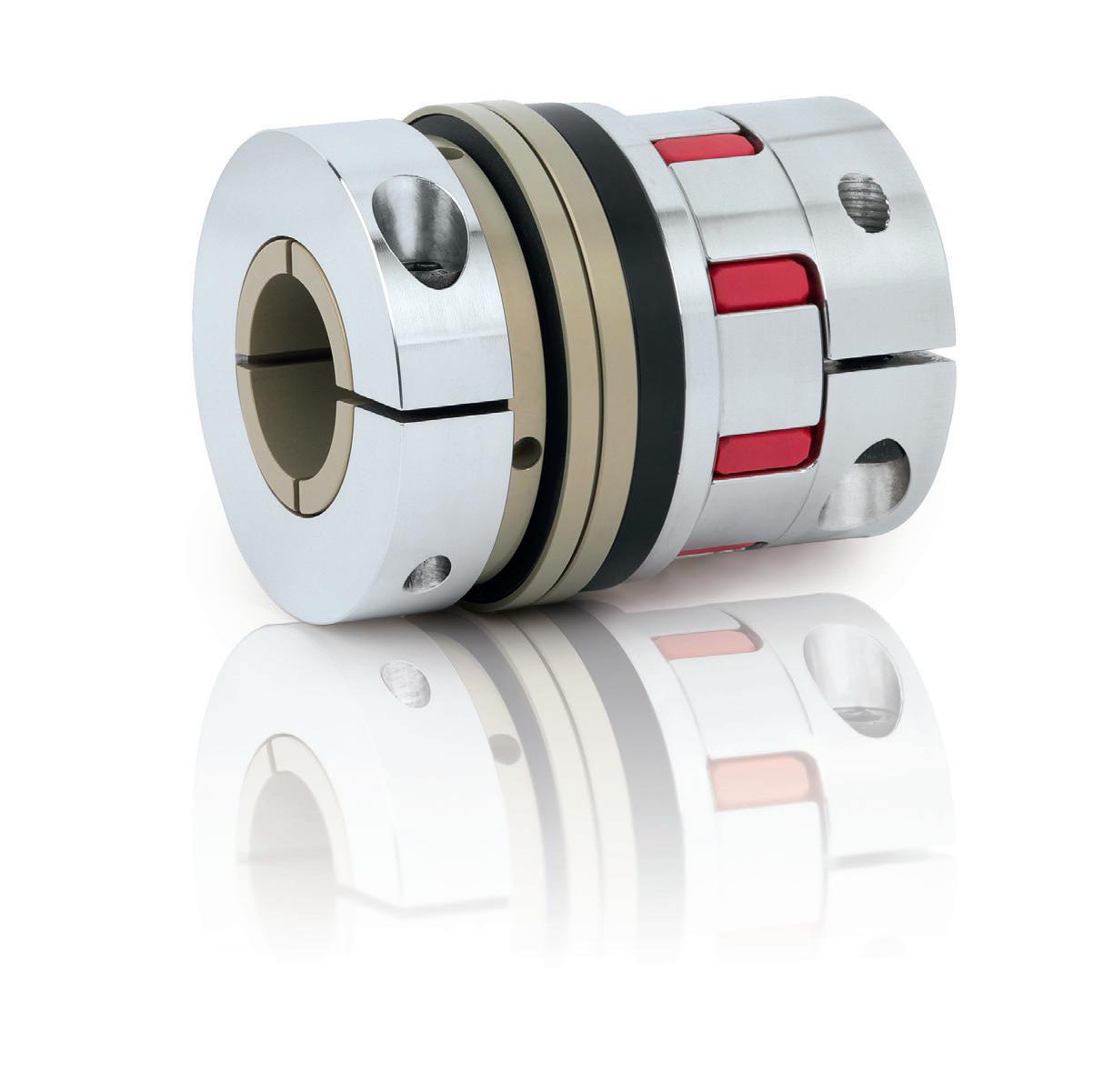
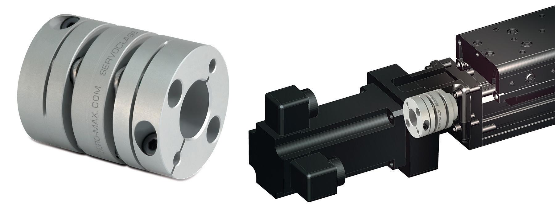
Depending on a number of factors including cost and desired accuracy, the drive mechanisms for positioning stages and tables can vary significantly. For instance, stages can be direct-drive types driven by linear servomotors or by a combination of motors, gears and couplings. They can be linear or rotary actuator driven, either using electric actuators or other types. Some other common methods include belt and pulley systems, ball screws or lead screws. Precision and accuracy requirements can also dictate design decisions such as what components to use in assembling a positioning stage.
For stages requiring reliability and high accuracy, air bearings are often used to minimize friction. Air bearings support a load with a thin film of pressurized air between the fixed and moving elements. They’re typically referred to as aerostatic bearings, because a source of pressure rather than relative motion supplies the film of air. For instance, so-called planar stages are typically constructed of air bearing guides and linear motor drives.
Unlike ordinary bearings, the surfaces of an air bearing do not make mechanical contact, so these systems don’t need lubrication. Because the surfaces do not wear, the systems don’t generate particulates, which makes them suitable for clean-room applications. When supplied with clean, filtered air, the bearings can operate without failure for many years.

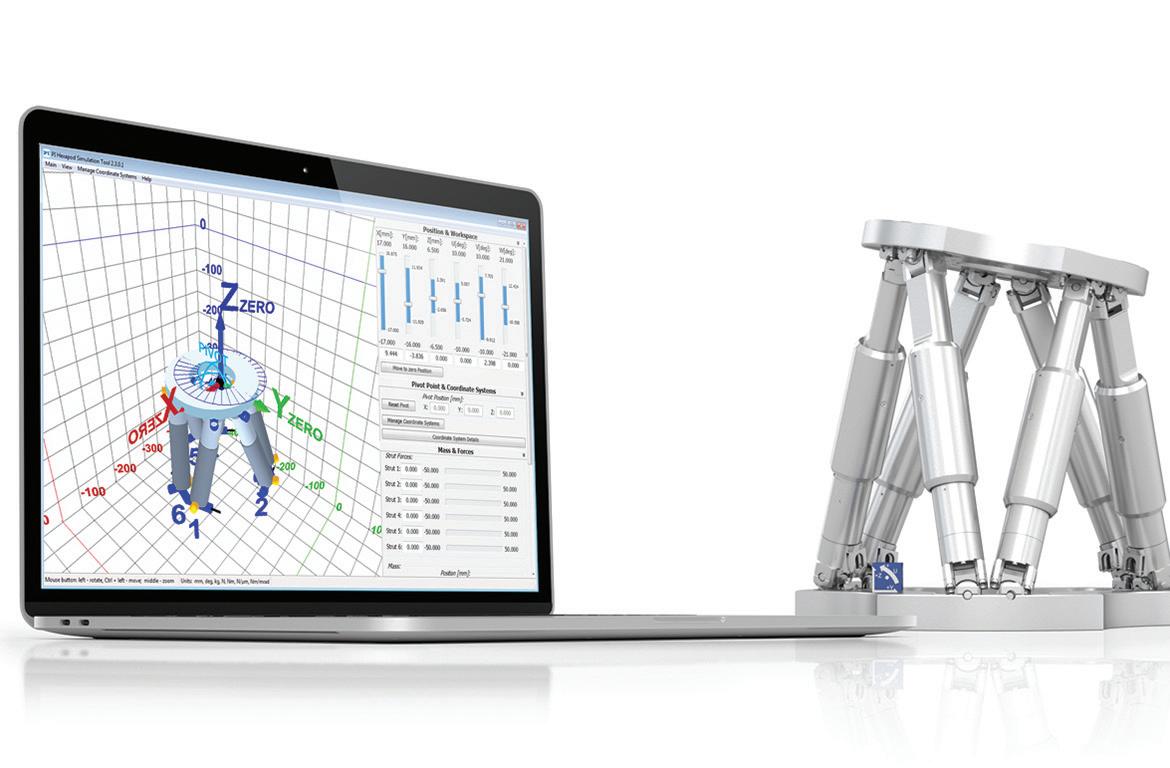
Many manufacturers offer software selection tools to help engineers size and pick the right stage or table for a given application. For example, simulation software from PI (Physik Instrumente) helps determine if a hexapod (or Stewart platform) is suitable for a specific positioning task, in terms of workspace, load, center of mass, and operating orientation.
TABLES
So-called X-Y tables are similar to X-Y Cartesian systems, in that they have two axes (X and Y, as their name implies) mounted on top of each other, and typically have strokes of one meter or less. But the key difference between X-Y Cartesian systems and X-Y tables lies in how the load is positioned. Instead of being cantilevered as in a typical Cartesian system, the load on an X-Y table is almost always centered on the Y axis, with no significant moment created on the Y axis by the load.
X-Y tables generally work only within their own footprint, meaning the load does not extend beyond the Y axis. This makes them best suited for applications where a load needs to be positioned in the horizontal plane (X-Y). A typical example is a semiconductor wafer being positioned for inspection, or a part being positioned for a machining operation to take place. Designs referred to as
“open-frame” or “open aperture” have a clear opening through the center of the table. This allows them to be used in applications where light or objects need to pass through, such as back-lit inspection applications and insertion processes.
Because X-Y tables are primarily used for high-precision applications, the guideway of choice is crossed roller slides, which provide extremely smooth and flat travel. Drive mechanisms are typically ball screws or linear motors, although fine pitch lead screws are also common.Pitch and yaw moments can cause edge loading on the bearing. Image courtesy of NSK
How to define roll, pitch, and yaw for linear systems

Linear guides and systems —
including Cartesian robots, gantry systems,and X-Y tables — are typically subjected toboth linear forces due to downward, upward,and side loads and rotational forces due tooverhung loads. Rotational forces — alsoreferred to as moment forces — are typicallydefined as roll, pitch, and yaw, based on theaxis around which the system tries to rotate.A moment is caused by a force applied at a distance. A moment force does not cause rotation, although it is often confused with torque, which is a force that does cause a body to rotate about an axis.
To define roll, pitch, and yaw in linear systems, we first need to establish the three primary axes: X, Y, and Z.
The two axes of the horizontal plane are typically defined as X and Y, with the X axis being in the direction of motion. The Y axis is orthogonal (perpendicular) to the direction of motion and is also in the horizontal plane. The Z axis is orthogonal to both the X and Y axes, but it is located in the vertical plane. (To find the positive direction of the Z axis, use the right-hand rule: point the index finger in the direction of positive X, then curl it in the direction of positive Y, and the thumb will indicate positive Z.)
In multi-axis systems, the direction of travel of the bottom axis is typically defined as the X axis. If the next axis above it is also horizontal, that axis is defined as Y, and the vertical axis (even if it is the second axis, directly on top of X), is defined as the Z axis.
Roll, pitch, and yaw are rotational forces, or moments, about the X, Y, and Z axes. Just like pure linear forces, these moment forces need to be considered when calculating bearing life or determining the suitability of a linear system to withstand static loads.
Roll: A roll moment is a force that attempts to cause a system to rotate about its X axis, from side-to-side. A good example of roll is an airplane banking.
Pitch: A pitch moment attempts to cause a system to rotate about its Y axis, from front to back. To envision pitch, think of the nose of an airplane pointing downward or upward.
Yaw: Yaw occurs when a force attempts to cause a system to rotate about its Z axis. To visualize yaw, imagine a model airplane suspended on a string. If the wind blows just right, the airplane’s wings and nose will remain level (no rolling or pitching), but it will rotate around the string from which it’s suspended. This is yaw.
Both pitch and yaw moments put excess loads on the balls located at the ends of a linear bearing, a condition sometimes referred to as edge loading.
Recirculating bearings with a “back-toback,” or “O,” raceway arrangement have higher roll moment capacities than bearings with a “front-to-front,” or “X,” arrangement, due to the larger moment arm formed by the contact lines between the balls and the raceways.