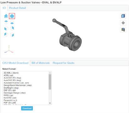
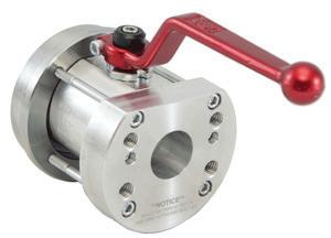
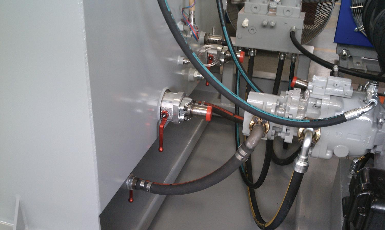
Tompkins Ball Valves





Safeguard unsafe areas with affordable safety components from AutomationDirect
Common Sense is Great, but Sure-Fire Protection is Better
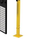
AutomationDirect has a comprehensive portfolio of certified machine safety components to guarantee your equipment is protected and your personnel are safe. A wide assortment of safety components from trusted brands in the industry is available including cable pull safety switches, hazardous area safety devices, safety relays and much more. All are in stock at low everyday prices, so you can keep your system safe without breaking the bank.










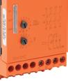

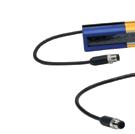
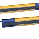
Starting at $777.00
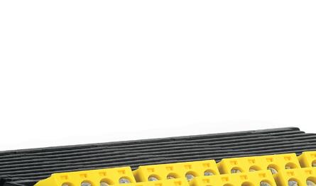
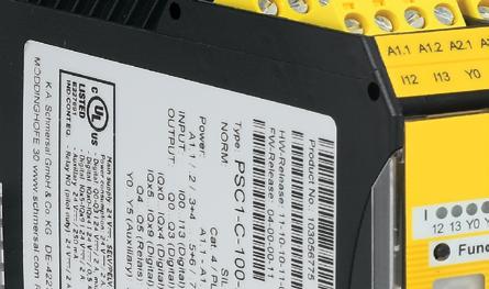
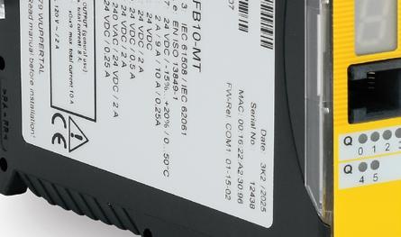
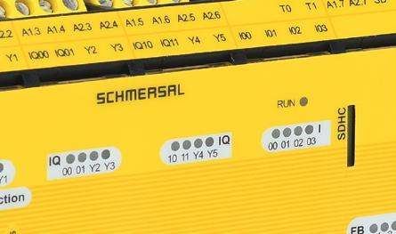
The Schmersal PROTECT PSC1 safety control system is a compact, programmable safety control system with scalable I/O. E-Stops, light grids, and almost any safety device can be monitored with ease. The universal interface ensures instant connection to every standard fieldbus. All of this from a well-known brand in safety equipment.

The PSC1 Safety Controllers include the following features:
• Safety functionalities up to SIL 3 according to IEC 61508 / IEC 62061, PL e and Cat. 4 according to EN ISO 13849-1
• 14 safe inputs up to PL e or SIL 3, 4 safety semiconductor outputs, 2 relay outputs, and 2 pulse outputs
• Modular expansion with up to 216 inputs/outputs, using one part number for each expansion
• Built-in fieldbus connectivity without the need to purchase communications modules
• The PSC1-C-10 has 2 built-in signaling outputs, and the PSC1-C-100 adds 20 configurable I/O points that can be set as inputs or outputs, and 6 signaling outputs











Mary C. Gannon • Editor-in-Chief

WHILE AT CONEXPO/CON-AGG earlier this year, I noticed a few themes running through many of the booths. One was the discussion over steering, and I cover that in a multisource trends piece on page 22. Closely tied into this is the notion that software has moved from “nice to have” to core infrastructure in fluid power design.
Nearly all these conversations about the growing need for software are linked to the shortage of highly skilled operators and engineers, with the need to make complex machines more manageable by less experienced people. For example, Bosch Rexroth experts Terry Hershberger, Mobile Hydraulics Technology Leader and Gunther Nunweiler, Vice President Sales, Mobile Hydraulics, Bosch Rexroth USA, said their softwaredriven systems let a less-skilled operator achieve the same quality of work as a seasoned expert. For example, electronic opencircuit and closed-loop controls (EOC/EEC) allow software, sensors, and feedback loops to handle precision and response, while the operator simply “drives” the machine. They added that’s why steering and control design within machine cabs are reflective of gaming-style joysticks, offering vibration feedback, geofencing, and automation of repetitive motions. These let someone without 10 years on a backhoe still dig a precise trench or work near hazards safely.
The key for software is to make machines smarter to stretch talent. Even the OEMs agree — during a presentation to the media, LuiGong said that in their smarter machines,
operators can choose simple presets (hammer, mass excavation, grading, etc.) on a monitor, and the control software reconfigures the hydraulics for them. That removes tuning complexity and lowers the skill barrier for productivity and fuel economy.
On the engineering side, it is becoming difficult to find skilled software engineers, as they are lured away by tech giants. This is driving a need for reusable software platforms and ecosystems where users can plug and play from a curated set of components rather than build from scratch, said Matthias Goebel, President & CEO Bosch Rexroth Compact Hydraulics.
This is where AI is coming into play. It can be used to help generate and test code, making functional safety-rated software development more manageable with fewer people, said Luke Wadsley, Director of Engineering Solutions, North America, Danfoss. Rexroth’s Nunweiler agreed, saying that AI and sensor data enables adaptive control and automation, so fewer engineers can cover more complex control strategies.
Simple tools are required to allow nonsoftware engineers to program a machine. Wadsley emphasized the need to move from tuning individual components to optimizing the pump, valve stack, and prime mover together. That shift relies on model-based design, starting in simulation, then carrying the same software into testing and deployment so functional safety and cyber resilience requirements can be met without rewriting code at each step. He pointed out
Danfoss’ Plus+1 software blocks as an example, which allow users to build common machine functions faster.
Ross Johannes, Application Tech Services Team Leader, HydraForce, agreed with this need for simplistic use, as he detailed how bringing together HydraForce’s software with Bosch Rexroth’s hardware, gives users a complete, advanced package. “We've taken the HydraForce programming software, HFImpulse, which is graphical programming. It's drag-and-drop and very easy for an initiate, a journeyman, to configure and program. Then we put that on the Bosch controllers. So now we get the ease of use from the HydraForce side, and we get the top spec hardware from Bosch,” he told me.
How are you using software in your designs? Have simplistic block or dragand-drop programs allowed you to design machines faster? We’d love to hear from you, so please drop me a note. And don’t miss our intro story on Page 8 about Paro Software’s new HydroCam software, which was designed to simplify hydraulic manifold CNC programming. FPW


Mary C. Gannon • Editor-in-Chief mgannon@wtwhmedia.com linkedin.com/in/marygannonramsak
Building the right diagnostic kit for hydraulic troubleshooting
This guide breaks down budget, midrange, and premium test kits to help technicians quickly pinpoint losses in pressure, flow, and efficiency in hydraulic systems.
Steer by wire becomes the focus of automation in mobile machines
See how major manufacturers are reinventing steering to ensure safe and reliable control as machines become more autonomous.
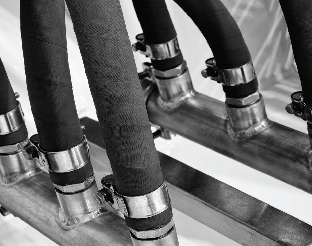
Hydraulic hose fundamentals
Learn some quick basics to hose assemblies and read about the latest innovations with these critical hydraulic system components.


EDITORIAL
VP, Editorial Director
Paul J. Heney pheney@wtwhmedia.com
Editor-in-Chief, FPW
Mary Gannon mgannon@wtwhmedia.com
Contributing Editor Josh Cosford
Contributing Editor
Carl Dyke
MARKETING
VP, Marketing
Annie Wissner awissner@wtwhmedia.com
Digital Marketing Manager
Taylor Meade tmeade@wtwhmedia.com


PRODUCTION
VP, Creative Services
Matthew Claney mclaney@wtwhmedia.com
Art Director, FPW Eric Summers esummers@wtwhmedia.com
Director, Audience Growth Rick Ellis rellis@wtwhmedia.com
Senior Associate, Audience Development
Marie Claussell mclaussell@wtwhmedia.com
SALES
Amanda Buehner abuehner@wtwhmedia.com
Ryan Ashdown 216-316-6691 rashdown@wtwhmedia.com Jami Brownlee 224.760.1055 jbrownlee@wtwhmedia.com
Jack Gillerlain
773.909.2718 jgillerlain@wtwhmedia.com
Susan Powers
708.341.3370 spowers@wtwhmedia.com
Judy Pinsel
630.538.2638 jpinsel@wtwhmedia.com


PRODUCTION SERVICES
Customer Service Manager Stephanie Hulett shulett@wtwhmedia.com
Customer Service
Representative
Tracy Powers tpowers@wtwhmedia.com
Customer Service Representative JoAnn Martin jmartin@wtwhmedia.com
Customer Service Representative
Renee Massey-Linston renee@wtwhmedia.com
Customer Service Representative
Trinidy Longgood tlonggood@wtwhmedia.com
LEADERSHIP
CEO Matt Logan mlogan@wtwhmedia.com
Co-Founders Scott McCafferty Mike Emich



Josh Cosford
I'M NOT OUT HERE TRYING to be a climate denier, but I'm also not going to deny that these past few winters and springs have been absolute trash. There's been too much cold, too much snow, and too much rain. Yes, yes, I've heard that places like the Southwest have been extraordinarily hot on occasion, and I thank the fluid power gods that it was so during the CONEXPO show. But there's a solid chance that at least half of you readers keep a snow brush in your car from October to April, and this article is for you.
An outlier is not a statistically significant representation of the mean, so climate scientists always remind people that weather is not climate. Okay, so how many years in a row do we need to have of this crappy weather before we admit we have a crappy climate? Well, according to the internet, that period is thirty years. For what it’s worth, this 51-year-old spends an increasing amount of time researching warm “climates” in which to retire, so don’t expect me to wait around until 2056 to see if Ontario winters are still brutal — snowbird life, here I come.
And because I’m a 51-year-old, I spend enough time watching the Weather Channel that I’ve heard the excuses that the Latino siblings of the Pacific sea-currents are to blame. Apparently, it’s La Niña contributing to my requirement for sweaters in early May, despite being a Canadian who’s known to wear shorts in the winter. So, with this latest spell of cold “weather” running well into the spring, what’s a fluid power professional to do about their machinery in progressively cold and wet conditions?
It sounds obvious, but purchase new machinery. If you’re unwilling to rid yourself of that ’68 Deere tractor, then don’t complain when you’re clearing ice or condensation off your inside windows like you’re driving a ’68 Beetle. New machinery is just so damn good.
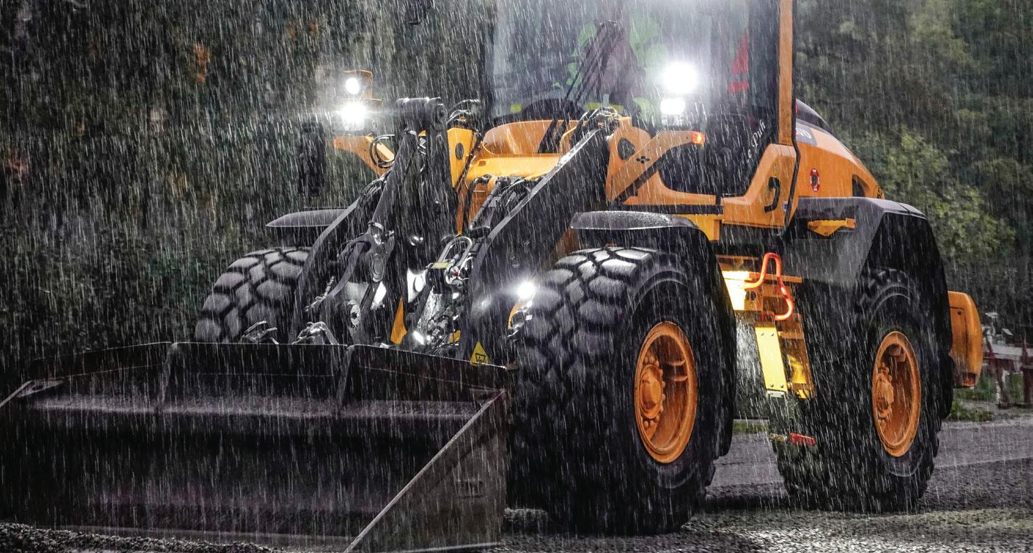
The cabs are warm and cozy, with heated seats and window defrosters all around. They have great stereos, cup holders, and Apple CarPlay.
The benefits of new machinery go well beyond comfort, of course, or you'd be reading this article in Applied Ergonomics magazine. New machines withstand harsh weather by employing advanced technology, materials, and construction. Machines are optimized for high-viscosity index fluids, which prevent coldstart issues and make pumping easier, offering a "get in and go" level of productivity. The days of firing up your excavator and letting it run until you've finished your Dunkin or Tim's coffee are long gone.
New machines offer superior protection of the hydraulic fluid and all the components it circulates through. Sealed reservoirs, advanced seal technology, and weatherproof electronics all contribute to hydraulic reliability on par with any new car built for life in the North. Machinery isn't as "get in and drive for 8000 miles" level of maintenance-free, but centralized lubrication, electronic sensors, and condi-
tion monitoring will keep you working through even the rainiest of spring weather without getting drenched greasing, filling, or inspecting.
Just like new cars, new hydraulic machinery is eye-wateringly expensive — remember when a $100,000 vehicle was only made in Italy and came with a V12? I can’t tell you how to run your business, so only you can decide if you’ve got half-a-mil’ of financing capacity, and if it increases your productivity enough to make sense. If you can’t swing it, you always have the option of selling the farm and moving to Del Boca Vista. FPW


Josh Cosford • Contributing Editor jcosford@higginson.ca linkedin.com/in/joshcosford


By Mary C. Gannon • Editor-in-Chief
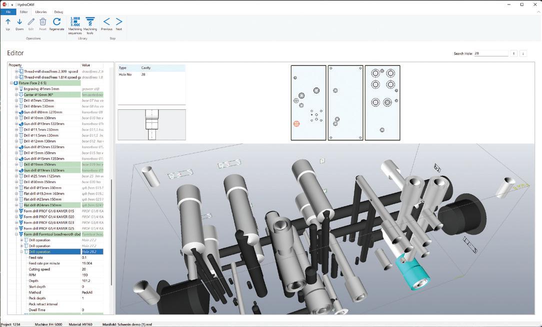
Hydraulic manifold machining is challenging to say the least. Traditional CAM software was built for external shapes: contours, pockets, profiles, among others. It was never designed for the inside-out world of hydraulic manifolds, which features a complex internal grid of precisely intersecting holes, cavities, and ports with extremely tight tolerances.
As a result, programming manifold machining into a CNC machine can take hours for each manifold. That was why the team at Paro Software set about to create a new software, HydroCam, to simplify hydraulic manifold CNC programming.
Typically, you import a 3D model and the software attempts feature recognition: analyzing geometry to classify holes, pockets, and profiles. For prismatic parts with simple external features, this works reasonably well.
For manifolds, such a process can break down. You have dozens of intersecting internal holes: cavities, ports, through-drills, threaded connections, many of which share common diameters and depths but require completely different machining sequences depending on their type, not just their geometry. A C10 cavity and a Sun 11A cavity might look geometrically similar but require entirely different tool sequences.
This requires the programmer to be extra careful in reviewing the process, checking each hole manually one-by-one in the model and ensuring they're correct. If not, machining will be wrong and you will damage material. This process usually requires a skilled operator who knows the parts and can scan and read the schematics to ensure they’re correct. If that person ends up out sick or leaves the company, you’ve lost your knowledge bank.
After several years of development, Paro has officially launched its HydroCam software.
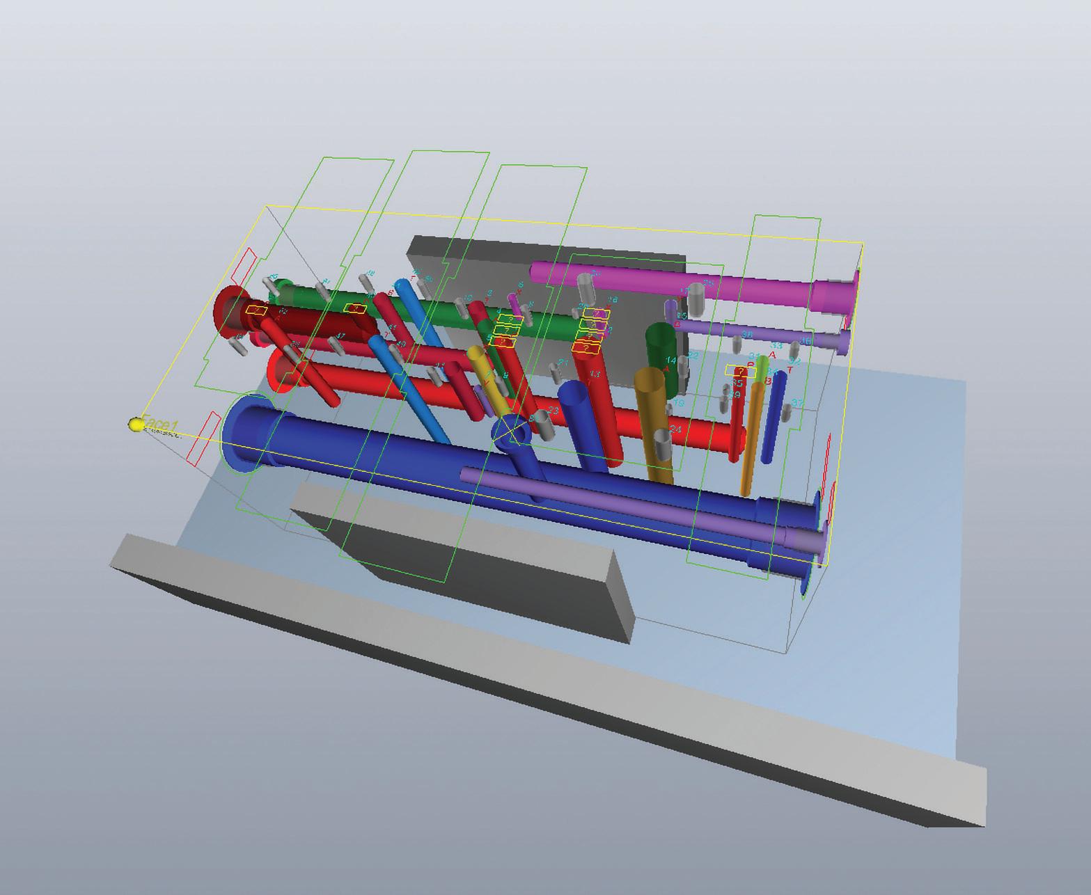
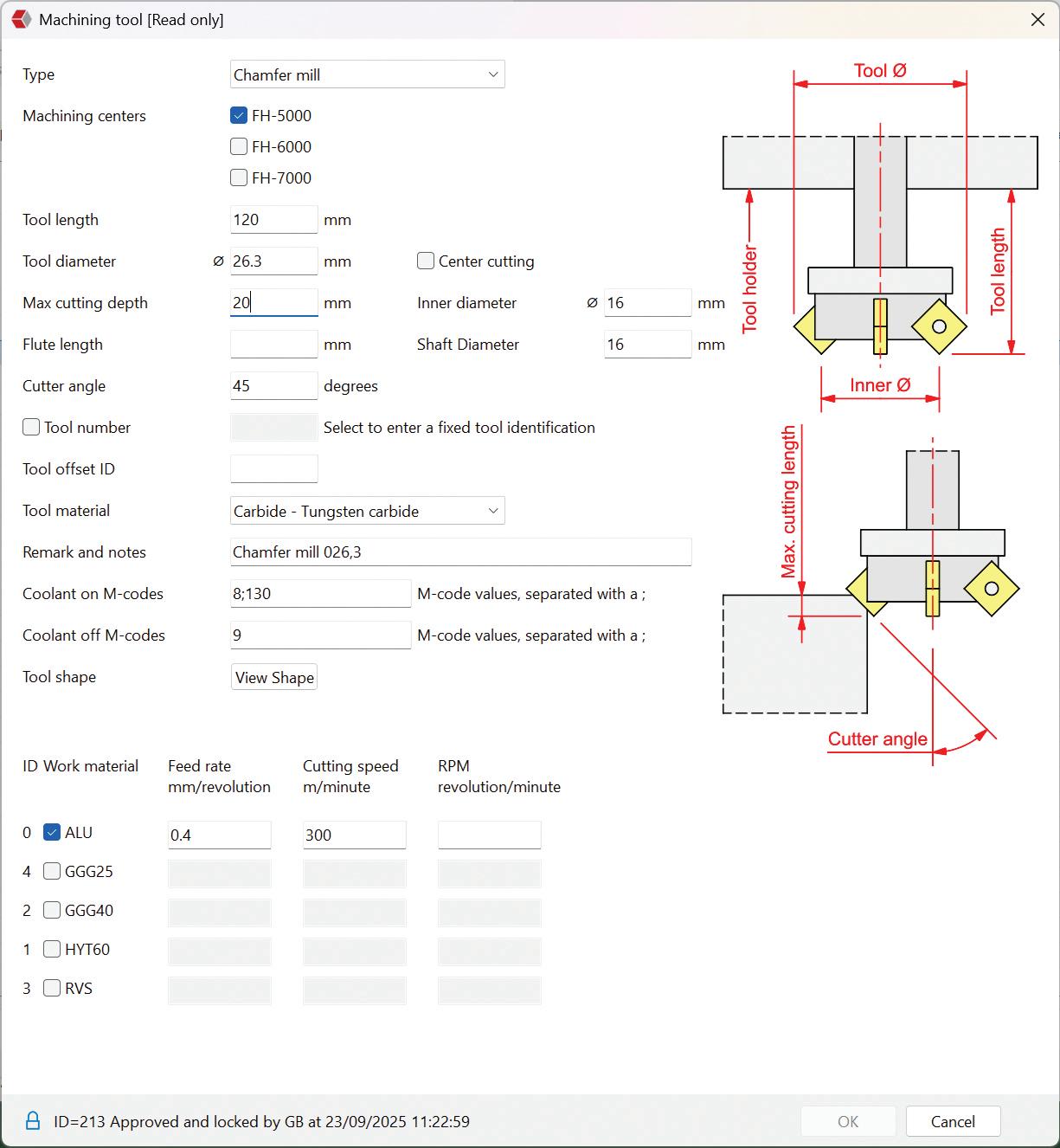
It works directly with HydroMan, Paro Software’s manifold design environment, and imports all geometry and coordinate data automatically, generating a ready-to-run CNC program in minutes. It automatically generates precise, accurate CNC programs by reading the intelligent data in HydroMan’s designs. Users can integrate custom manufacturing knowledge, such as drilling strategies, parametric depths and diameters, override feeds and speeds, and defined order of operations.





“What we do is we reduce CNC programming time from hours to a couple of minutes,” Marc Paro, CEO, said. “We managed to create the missing link in our product portfolio, because we want to provide the solution where you can be as efficient as possible. People cannot wait two weeks for a design, and then after that, another three months for their hydraulic manifold.”
HydroCam was the next step in Paro’s already existing software platforms. They currently offer HydroMan, which is for designing hydraulic manifolds, and HydroSym, which allows users to create accurate schematics in minutes.
“We thought a hydraulic manifold is nothing else than a translation of a hydraulic schematic, because you define your hydraulic manifold already in your schematic. So we developed a very good tool to draw your hydraulic schematic with,” Paro said. “The combination between HydroMan and HydroSym is a very powerful combination, because it takes over all the intelligence.
“We noticed that machining the manifold could take quite a lot of time, because there wasn't a solution which enables the user to generate and then create a CNC program from the drawing with standard CAM packages. It takes about four, five, up to six hours for a drawing. And we thought, we should do this more efficiently, because we have all the data already within the design. That was the beginning of the start of the development of HydroCam.”
Developing the program took several years because of the complexity but they launched earlier this year after partnering and testing with several manufacturers in Europe.
Initial setup takes time to implement and build the library, so it does require about 20 to 30 days, but once it’s set up, programming time is cut drastically down to minutes. Because you are building a compre-

HYDROCAM ADDRESSES THE CHALLENGE OF INTRICATE INTERNAL FEATURES OF MANIFOLDS.
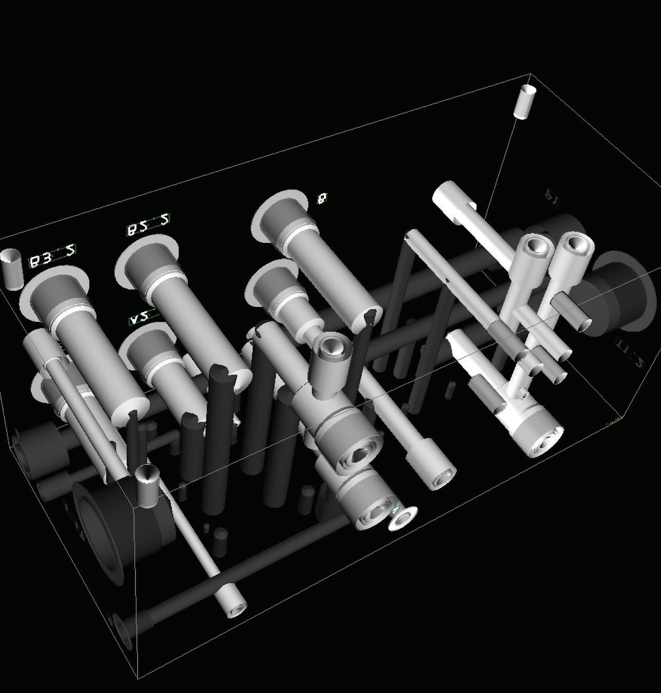
hensive set of cavity types across multiple materials, you’re looking at significant setup time. But it’s a one-time cost per sequence, not per manifold.
The library is where you encode your machining knowledge. Each sequence is a named recipe for how to produce a specific type of hole or cavity. A sequence defines:
• Applicability parameters: which cavity types the sequence covers, the range of locating shoulder depths it can handle, which machines and materials it’s valid for.
• Operation list: the ordered list of machining operations: center drill, through drill, form tool passes, threading, reaming, with complete tool assignments and default feeds and speeds.
• Conditional logic: e.g., a conditional pilot drill that is only inserted when the through-drill step doesn’t satisfy the pilot hole requirements for the subsequent form tool.
“Now the three packages are connected to each other. If you have a schematic of a manifold, you can design the manifold within an hour. And once you have designed the manifold, you have got your CNC program built in minutes,” Paro said. “What HydroCam does it is it puts all the knowledge of the manufacturer in a library, which enables them to run the CNC program without making any mistake or without searching for things, because it's predefined.” FPW
Paro paro.nl
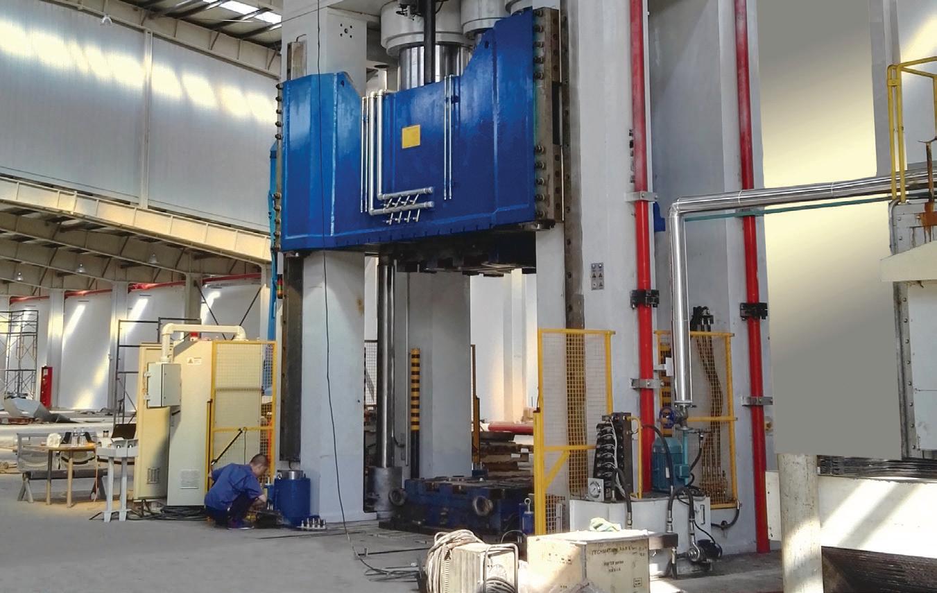


This press applies up to 3,000 tons of force to form composite automobile panels. Delta’s RMC provides multi-axis position and pressure control, ensuring perfect synchronization of every moving part.
Delta RMC motion controllers and graphical RMCTools software simplify complex motion design, making it smoother and more precise.
For the full case study on Wuxi LANLI Machine Tool Co. and other relevant applications, visit our website.
Watch our training videos to see how Delta Motion brings precision and harmony to your application.
Come see us June 22-25 in Chicago at









& 90°



Josh Cosford • Contributing Editor
MOTOR failure involves a combination of proper design, maintenance, and operation practices. Despite resembling hydraulic pumps, motors are unique in that they convert hydraulic energy (in the form of pressure and flow) into rotational energy (in the form of running torque). Hydraulic motors drive winches, wheels and pulleys, to name a few, making them a versatile actuator like none other.
However, when hydraulic motors’ needs are not met, failure is all but guaranteed. Compared to many other components, hydraulic motors face the most drastic conditions, harsh operating environments and most extreme pressures. To prevent hydraulic motor failures, I’ve compiled a list of 7 steps to help you keep you and your machine happy.
1. Ensure your hydraulic oil is clean, dry and properly viscous. Just as with other hydraulics, contamination is still the number one cause of hydraulic motor failure. Monitor the filter condition by observing its bypass indicator or changing the element at regular intervals if one is not present.
Motors are the most likely hydraulic component to be entirely submerged in water, such as those used in drive wheels for various mobile machines. Send oil samples regularly to analysis labs to check for water contamination, and use desiccant breathers to prevent excessive moisture.
Finally, employ tactics to maintain the oil within the ideal viscosity range, which requires cooling in warm climates and heating in cold climates. The extremes of temperature allow for metal-on-metal wear in the heat or possible cavitation and loss of lubrication in the cold.
2. Do not overload your hydraulic motor. Avoid exceeding the torque and speed rating of the motor, which can lead to excessive heat, cavitation due to flow demand when over center, and physical breakage when torque overloads the mechanical and physical capacity of the motor.
Side loading should also be monitored since damage to bearings, seals, and the shaft itself could result in catastrophic failure.
3. Properly install and align your hydraulic motor. Motors use shafts and usually turn other shafts, but they could also insert into gearboxes or other devices with a female interface. When possible, use alignment couplers with an isolating rubber insert to help absorb instant forces. Solid connections, such as with a metal sleeve, don’t allow for differences in axial, parallel and angular misalignment.
Also, the pilot fabricated on the machine side should be precise, axially true, and parallel, as this prevents the same issues described above. Doing so prevents wear to bearings, seals and pump internals.
4. Keep the temperature moderate. It’s not enough to keep the temperature of the hydraulic oil cool, but care should be taken to warm up a cold machine as well. Hydraulic oil and the machinery it powers prefer an operating window of viscosity, so in cold climates, ensure you install reservoir heaters when needed. Additionally, heat does more than reduce lubricity and increase oxidation; it also softens and damages seals, accelerates oil wear, and increases metal-to-metal wear inside your motor. Hydraulic coolers are cheap insurance compared to motors running in the thousands.
5. Clean and inspect your hydraulic motor. It sounds easy and simple, but it's the same reason a clean engine bay in your car makes for a reliable engine. When you clean and inspect your machine as a whole, you can identify leaks, cracked hoses, and heat discoloration that would otherwise go unnoticed with a greasy and dirty machine.
6. Route your case drain properly. You'll know you got this one right within the first ten minutes of machine startup since an incorrectly installed and routed drain results in near-immediate failure. Some hydraulic piston motors, for example, include two case drain ports to improve installation flexibility. Using the bottommost oriented port allows the case to drain entirely, leaving the pump dry of critical lubrication.
Install the uppermost drain on the motor, and then fill the pump case with
oil before startup. Although even with the correct orientation, the pump's internal leakage will still fill the case, the damage done by running the pump dry at startup will reduce the expected life by 90% within the first few minutes.
7. Select the correct motor for your application. It’s a non-starter if you’re either selecting or replacing a motor with the incorrect design for your application. If you require a high-speed motor to drive a drill, you must know that a bent-axis piston motor is a better choice than a gerotor motor, which is low-speed and inefficient.
When replacing a motor, always select the correct pressure and flow range that matches your factory-installed design. A larger motor will run more slowly with higher torque, and a smaller motor will run higher speed with less torque, for any given system pressure and flow rating.
With these seven tips, you will be sure to cover the required steps to prevent hydraulic motor failure, from new applications to repairs and maintenance. By doing so, you will avoid wasted time and costs now and in the future.
By Michael Tuohey • Regional Marketing Manager, North America, Piab
, safety is a core design requirement. As more processes become automated and rely on vacuum, the way vacuum systems are engineered has a direct impact on the safety of people, products, and assets. Piab’s approach places safety at the center, combining smart design, robust hardware, and intelligent control to minimize risk.
Engineering safety into everything: Safety starts with how each vacuum component is built. Vacuum pumps, suction cups, and grippers should be designed to maintain performance even in challenging environments, which reduces accidents caused by suction loss, unexpected drops, or equipment failures.
Redundant sealing surfaces, wear-resistant materials, and geometries ensure that suction cups retain their grip across many surfaces, from smooth glass to porous packaging. When a vacuum system holds reliably, operators are less exposed to falling loads, erratic robot movements, and unplanned intervention.
Protecting people around robots and cobots: As robots and cobots become common, the interface between human and machine must be especially safe. Vacuum gripping solutions on robotic arms for picking, placing, and palletizing ensure precise control and predictable behavior.
Controlled release of vacuum helps ensure that parts are not dropped or flung when the robot changes speed or direction. Vacuum levels can be tuned to match the weight and fragility of the product, reducing the chance of breakage or flying debris. When used with collaborative robots, soft and compliant suction cups add a layer of passive safety: they are more forgiving than rigid mechanical grippers if contact with a human occurs.
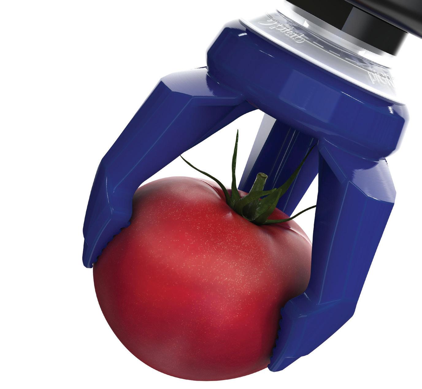
Built-in safety and monitoring: Modern vacuum systems increasingly rely on smart monitoring and control to maintain safe operation. By measuring vacuum levels, flow, and response times, advanced technology can detect developing problems early, such as a blocked filter, leaking line, or damaged cup.
When thresholds are breached, for example, Piab’s Smart system can trigger alarms, slow down the process, or stop it altogether, preventing small issues from escalating into dangerous situations. Integrated non-return valves and vacuum reservoirs maintain grip briefly even if air supply fails, giving controllers time to react and bring the system to a safe state.
In more advanced setups, predictive diagnostics can schedule maintenance before performance drops below safe levels. This reduces both unplanned downtime and the temptation to “keep running just a bit longer” with equipment that is no longer operating safely.
Product and contamination safety: Safety is not only about people; it is also about protecting the product and the process. In industries such as food, pharmaceuticals, and electronics, contamination or product damage can represent a significant safety and quality risk. Piab’s vacuum solutions support hygienic and contamination-aware design using appropriate materials, smooth surfaces, and components that are easy to clean and inspect.
Carefully controlled gripping forces help avoid crushing or deforming packages, which could otherwise lead to leaks, spills, or exposure to sensitive contents. For clean environments, low-dust and low-particle designs, and oil-free vacuum generation minimizes airborne contamination.
Compliance and risk reduction across the line: Every production line faces a unique combination of safety regulations, standards, and internal policies. By working with modular, wellengineered vacuum components, machine builders and end users can more easily design systems that comply with relevant safety standards. Documented performance data, standardized interfaces, and clear guidance on installation and maintenance make it easier to perform risk assessments and implement appropriate safeguards.
Vacuum technology also plays a role in minimizing energy consumption and noise, both of which impact long-term operator health. Efficient vacuum pumps, optimized flow control, and smart energy-saving functions reduce the load on compressed air networks and help maintain a safer, more comfortable working environment.
A safety-first philosophy: Safety with vacuum technology is as much about philosophy as it is about hardware. By treating safety as a design input from the beginning — rather than a box to check at the end — vacuum systems become inherently safer, more predictable, and easier to maintain. FPW
Piab piab.com
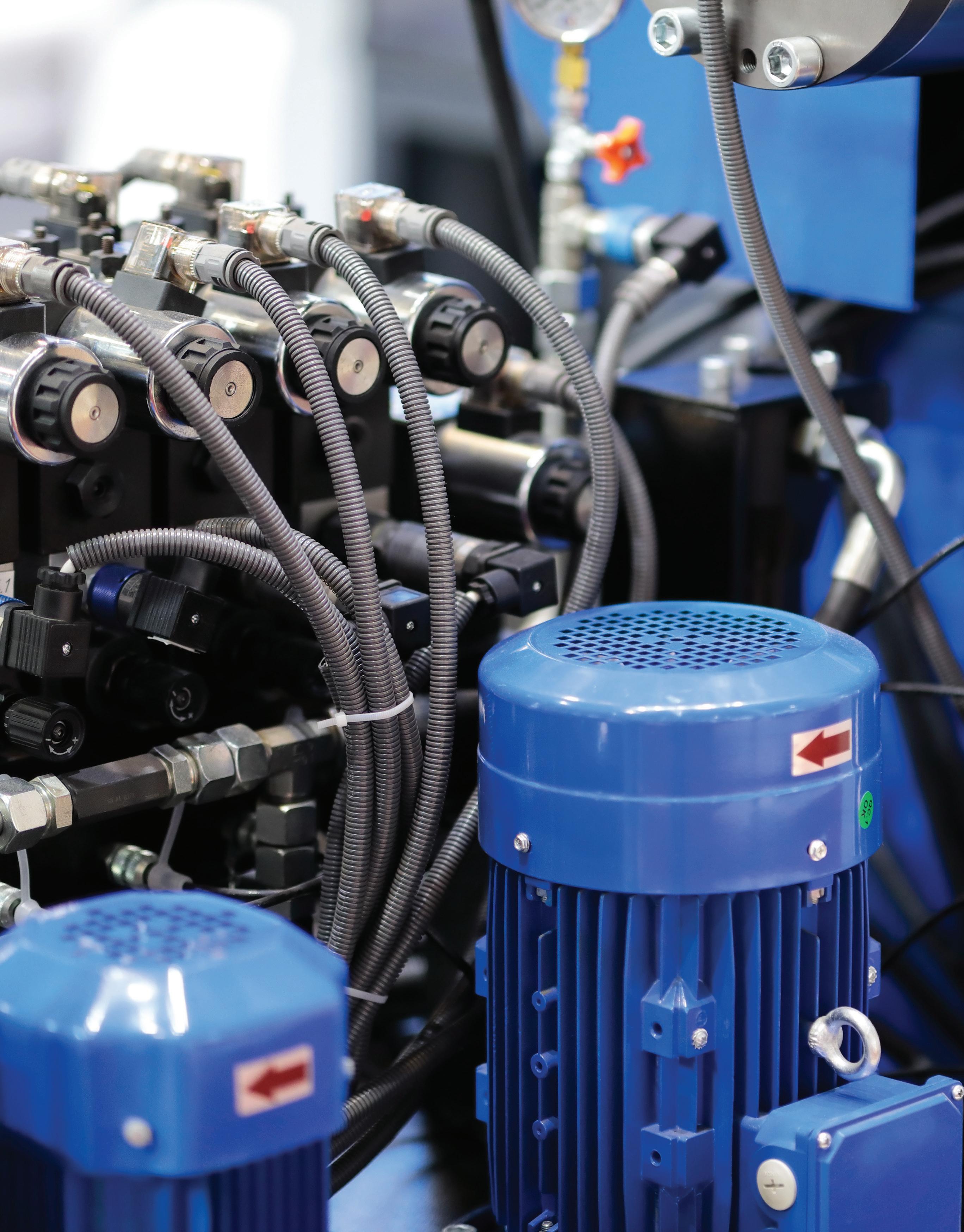
INDUSTRIAL HYDRAULIC SYSTEMS REQUIRE FUNDAMENTAL TROUBLESHOOTING SKILLS, AND ACCESS TO A VARIETY OF MEASUREMENT TOOLS TO GAUGE SYSTEM HEALTH.
This guide breaks down budget, midrange, and premium test kits to help technicians quickly pinpoint losses in pressure, flow, and efficiency in hydraulic systems.
HYDRAULIC TROUBLESHOOT -
ING requires a fundamental understanding of thermodynamics, experience with various machine types, as well as years of familiarity with various hydraulic schematics. In some ways, it's like being a doctor — even with a formal education, it takes years of exposure to (hydraulic machine) ailments to develop the knack for diagnosing and troubleshooting.
But just because the best hydraulic troubleshooters have years or decades of experience, doesn't mean you can't hit the ground running if you have the proper equipment and tips on how to use it. Whether you're just a new technician with
By Josh Cosford, Contributing Editor
a budding fluid power career or a veteran looking to upgrade your equipment, I've got three tiers of kit you can add to your shopping list to level up your diagnostics.
Before we dive into each kit and describe why each piece is necessary, let’s cover the foundations of hydraulic troubleshooting. Ninety percent of mysterious hydraulic failures manifest with symptoms of either reduced force or reduced speed. In either case, we use our testing accoutrement to discover the path hydraulic oil is taking where it shouldn't. The other 10% are catastrophic mechanical failures, where something breaks and stops working entirely, like a burnt-out solenoid coil or shorn drive coupler. The good news is that our kits can help
pinpoint both.
In many cases, machines experience reduced flow or pressure because there aren't enough oil molecules stuffing themselves into the appropriate location, either because they're refusing to let the pump push them around or because they're escaping unnoticed. A worn and bypassing pump, for example, will result in both reduced flow and pressure for every component downstream. By the same token, if many of the oil molecules being stuffed into a hydraulic cylinder are sneaking past the piston seal, both pressure and flow may be reduced.
A key characteristic of hydraulic energy is that anywhere it’s being lost before achiev-
ing useful work results in 100% heat generation. Oftentimes, finding that hot spot tells you precisely where to inspect for failure. In the case of the previously mentioned hydraulic cylinder, the fluid passing the piston is generating heat, and measuring heat at the suspected location would likely show an increase over the rest of the system.
Any good kit must also help diagnose the mechanical failures, and I would be so bold as to consider a burnt-out solenoid coil as such. A method to check the electrical components is helpful, so I’ll include tools to help here as well. More sophisticated test equipment, such as test stands for hydrostatic pumps or servo valves, will not be included to keep our kits portable.
Box of fittings & adapters
5,000
100
Inline
Needle
Screwdrivers
Laser thermometer
Bag of rags
The budget kit lets you test most of your hydraulic circuit, though some work will be required. The various fittings and adapters you have lying around the shop can be thrown into one toolbox, but be sure you have plenty of run tees in JIC, NPT, or whatever popular fitting standard you find in your location.
If absolutely nothing is happening hydraulically, and I mean not one function, first check the electric motor is turning,
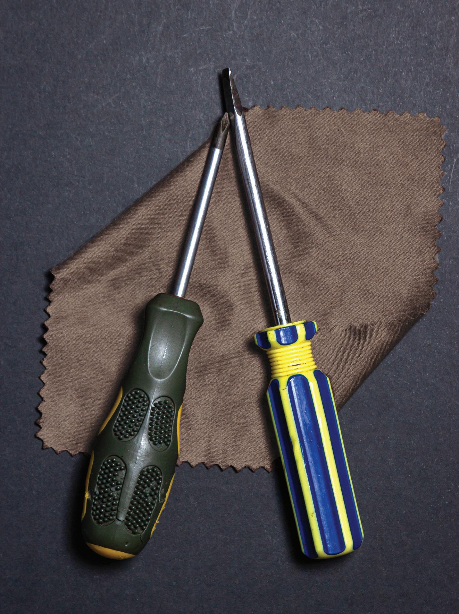
which is as easy as looking at its cooling fan. If the motor is on, then confirm the drive couplers haven’t disintegrated. This first tip applies to test kits, and the most you’ll need here is a screwdriver to remove the protective cover on the bellhousing. Speaking of screwdrivers, they’re great for checking for power at a valve coil by simply touching it to the coil to feel if it's magnetized — no multimeter required.
You'll need to disconnect the pressure, work, and return lines to install pressure gauges at various spots, using your hydraulic schematic to scout the best locations. You'll need plenty of ripped-up T-shirt rags, which are quite inexpensive — I wonder if moms realize their old kid’s clothes tossed into those donation bins are eventu-
ally soaking up grease and not, in fact, being sold at the thrift store as cute hand-medowns.
After installing a pressure gauge and flow meter after the pump, safely deadheading a cylinder function should spike system pressure, and if the measurement doesn’t match the schematic, fluid is bypassing somewhere instead of creating full force. The flow meter tells you if the pump is the culprit or if the leakage is downstream. The needle valve can be installed in the primary pressure line to load up the pump if you can’t artificially load it by activating functions. Just be sure the needle valve's default flow rate is higher than the pump's flow rate and that it is installed downstream of the relief valve in a fixed-flow circuit.
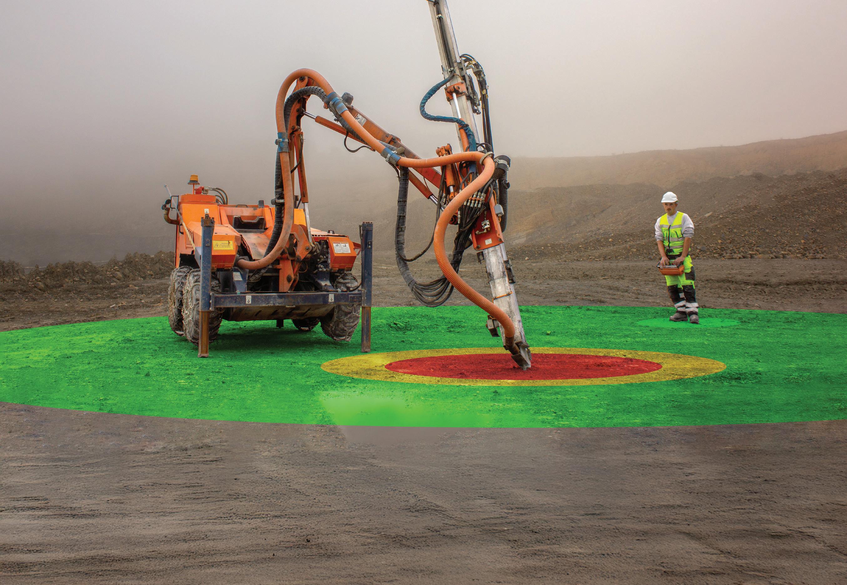
When operating heavy machinery, only a safe distance is the right distance. Getting too close to an activated machine can be just as dangerous as controlling without seeing the machine and the work environment. The solution is radiomatic® range control. By detecting the operator’s distance to the machine, this intelligent assistance feature keeps personnel and equipment always in a safe distance.



The laser thermometer is a great tool for pinpointing hot spots to see if bypass is excessive in any one component. Bypass will often be 20-50 degrees higher than what you'll measure at the reservoir, so check anywhere that could be leaking or simply stuck open, such as relief valves, directional valves, bypass flow controls, cylinder pistons, and tank lines. If any localized area is excessively hot, inspect the component for wear elements, such as seals, valve plates, or spools.
Midrange Kit - $2,400
Pressure test kit
Digital pressure gauge
Digital multimeter
Inline hydraulic tester
Test manifold
Oil handpump Kitty litter
Onto the midrange kit, which offers similar functionality to the budget kit but with a more professional, comprehensive assortment of components that are easier to use. The pressure test kit includes a custom case with protective foam inserts for your three pressure gauges, test point adapters, run tees, and microbore hoses. You can select the pressure range of the gauges, but 150, 3,000, and 8,000 psi are a good starting point.
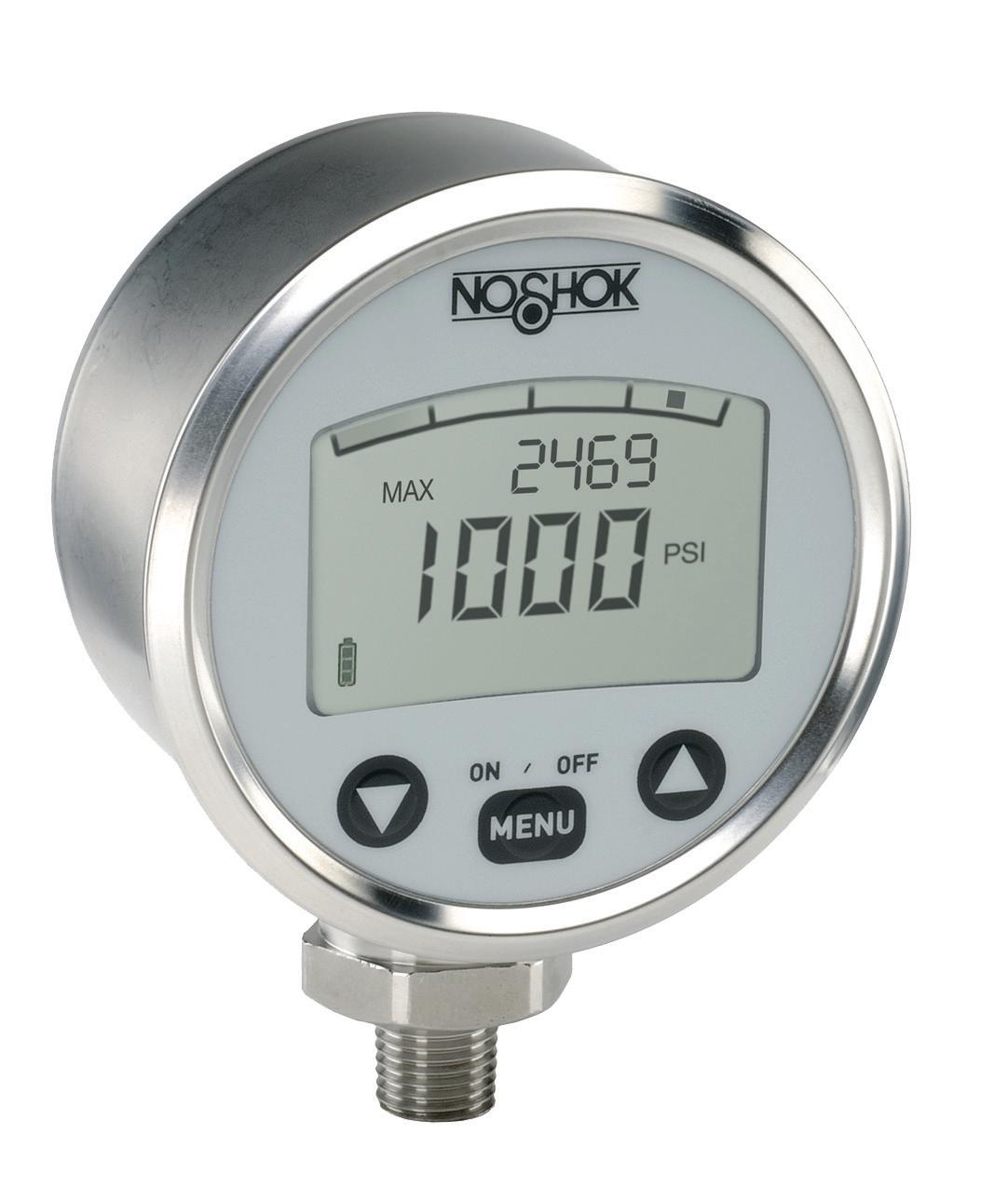
This test kit includes myriad test points with various thread forms, such as ORB, JIC, and NPT, and each form includes a few run tees that can be spliced into plumbing lines — hopefully you have plenty of bushings left from your budget kit to adapt sizes. I've included a digital pressure gauge in this kit, some of which have a memory function, allowing you to recall measurements from previous tests. This allows you to easily confirm that your solutions are progressing effectively towards resolution. Because
DIGITAL PRESSURE GAUGES ARE INCLUDED IN THE MIDRANGE KIT, BECAUSE THEY CAN BE MORE ACCURATE AND MAY ALSO HAVE A MEMORY FUNCTION, ALLOWING YOU TO RECALL MEASUREMENTS FROM PREVIOUS TESTS.
the test points fit universally, you can move the digital gauge around as required and then leave some of the mechanical gauges in strategic places.
The multimeter addition takes the "magnetized screwdriver" test to the next level, and allows you to confirm the actual voltage and amperage seen by the coil, since a simple magnetic field doesn't always tell the whole story. You can also use it to confirm that control signals from the PLC are functioning, double-check analog outputs, and verify that relays are passing current.
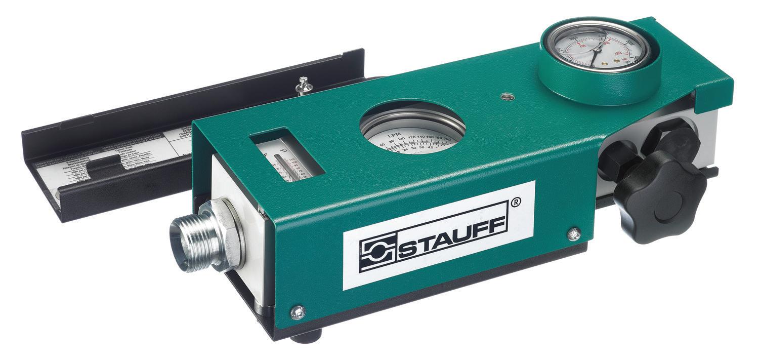
The inline hydraulic tester is a single unit that provides one-stop shopping for the critical data you need, which requires multiple components from the Budget Kit to reproduce. It contains a flow meter, a pressure gauge, a needle valve, and sometimes temperature sensors. It's installed wherever you want to check pressure, flow, and temperature, such as the primary pump pressure line or actuator work lines. You can use its needle valve to load up a pressure-compensated pump or check for flow and pressure where there should be none.
A test manifold is a neat little block with multiple inlets that feed into a single pressure-reading unit, usually a pressure gauge. They are sometimes a rotary dial that allows you to select the pressure source to measure, but may also be a bar manifold with each inlet isolated with a needle valve. This allows remote pressure monitoring without having to move about the machine.
I think the kitty litter is an obvious tool to help clean up oil spills, which is easier to use and re-use than rags, but some of you may be wondering what the handpump is used for. Sometimes you want gentle, pre-
cise control of the flow for testing, such as checking for leakage and bypass in cylinders, pumps, or motors. For example, if a cylinder is suspected of leaking across the piston, installing the handpump on one port and slowly pumping to observe leakage out the opposing port prevents the mess you might see with blasting full pump volume at the cylinder with one port removed.
Premium Kit - $20k +
Electronic data recorder
Various transducers
Displacement flow meter
Thermal imaging camera
Oscilloscope
High-pressure handpump
Oil absorbent mats
The Premium Kit accomplishes much of the same as the Midrange Kit, but adds a level of sophistication and technology that
speeds up testing and troubleshooting. We do away with mechanical pressure gauges and run entirely on electronics: pressure transducers, temperature transducers, water-saturation sensors, particle counters, and any other device that can measure a property of hydraulic fluid.
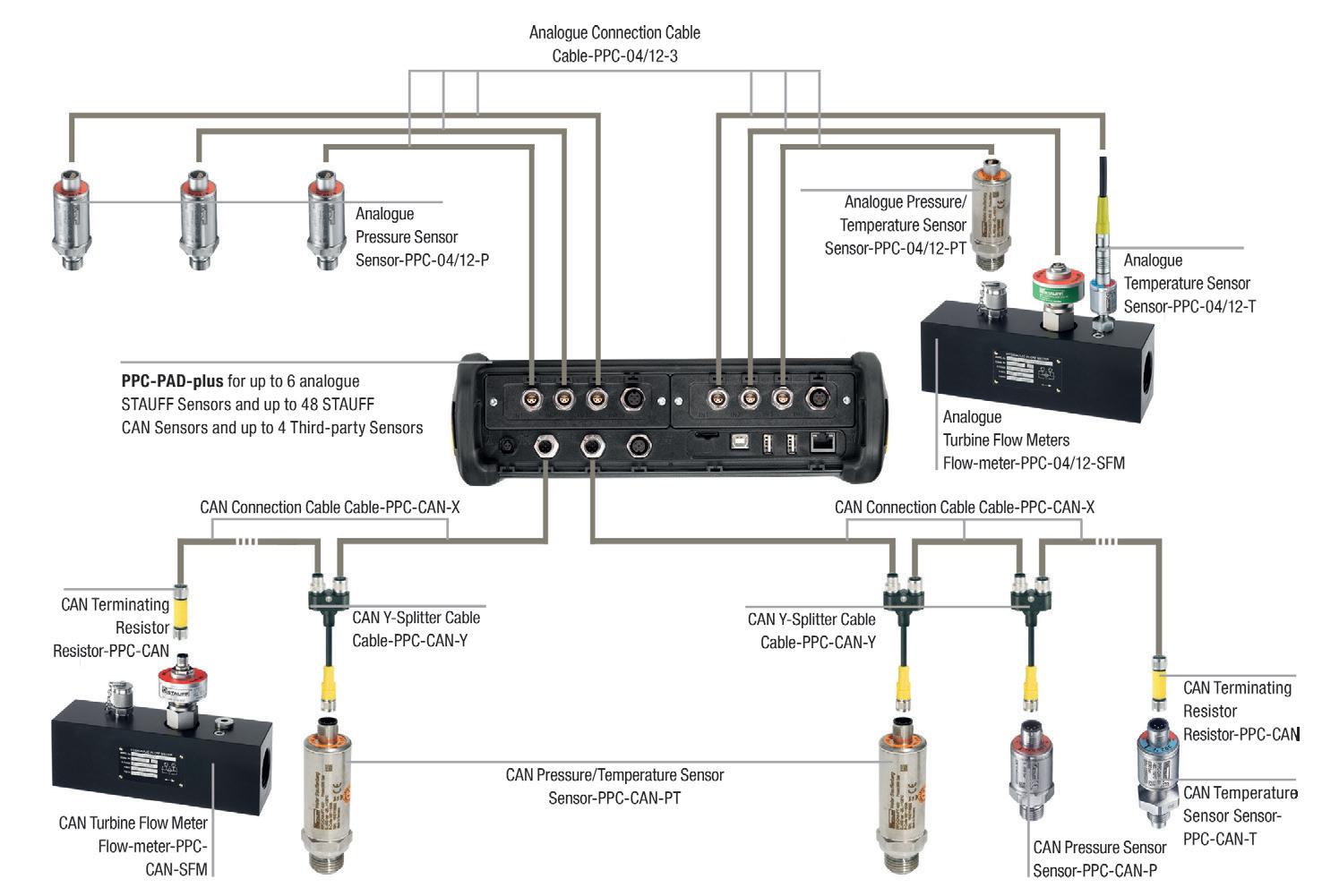
Each transducer feeds into your handheld, touchscreen diagnostic tool, which accepts a multitude of analog or CAN inputs, providing real-time data and memory functions. Instead of observing mechanical or digital pressure gauges, your transducers can measure accurately to within 0.5% or better while logging as finely as 0.1 msec to see how quickly valves are shifting or pumps come on pressure.
TOOLS
Your inline flow meters use highly accurate gears and a Hall-effect sensor, which, as you guessed, can be logged for accurate analysis of proportional valve performance or case drain leakage. You can even compare pressure curves with flow curves to ensure that the actuator's acceleration and frequency response are in line with expectations.
The thermal imaging camera takes the laser thermometer idea to the next level. You can take snapshots of entire subassemblies, such as the power unit or hydraulic manifold, and then compare heat at various points and during various operations. You can compare such images to previously logged "normal" operations to see if any
hot spots provide clues to heat-generating internal bypass.
The high-pressure handpump should be capable of 10,000 psi and will be used for advanced tactics to help improve performance rather than simply diagnose failures. A customer may want increased pressure capacity in a hydraulic cylinder, so, besides explaining to them that increasing pressure reduces the safety factor of a cylinder, the pump can be used for destructive testing on various new high-pressure seals you may prototype.
Then you have your ultimate nerd device — the oscilloscope. These are actually quite inexpensive these days, and much smaller than the suitcase-size units your grandpa used. I only put them in the Premium Kit because it’s not a tool for every skill level. These allow you to check actual voltage waveforms to detect weak or intermittent power to valves, confirm the analog output from transducers when PLCs are having trouble reading them, and data log advanced machine functions to help with diagnostics. It turns the invisible into the visible, and I might even suggest users of the Budget Kit obtain one just to see how the electric bits of your system operate.
Finally, we come to the fluid spill cleanup champs: the oil-absorbing mats. These are available in "socks" to stop the movement of oil across the floor or reservoir top when you know the tidal wave is inevitable. The oil-absorbing flat mats are great to lay down under your work area so that drips and leaks are caught before they hit the floor, avoiding the need to break out the rags or kitty litter. They're a bit more expensive, but certainly the most effective.
With any of the kits above, you're already a step ahead of troubleshooting neophytes. You still need to understand the principles of hydraulics, along with some time spent digesting schematics (I recommend using multiple printed copies and colored highlighters). If you can’t afford a whole kit as I’ve recommended, just start building your collection and work your way up. Before you know it, you'll have built yourself a Premium Kit any hydraulic troubleshooter would envy. FPW

MODERN STEER-BY-WIRE SYSTEMS ARE CHANGING THE WAY MACHINES CAN OPERATE, ENSURING SAFETY, RELIABLE OPERATION AND MORE AUTONOMOUS FUNCTIONALITY.

See how major manufacturers are reinventing steering to ensure safe and reliable control as machines become more autonomous.
By Mary C. Gannon, Editor-in-Chief
AT CONEXPO earlier this year, I had an opportunity to hail a ride from a Zoox taxi, an autonomous vehicle that provided rides to very specific destinations. That’s what really stood out to me as we cruised from the Zoox station at Resorts World to the Luxor — it was a set, pre-programmed route. We needed to walk about 20 minutes just to get to Resorts World to catch a ride in the carriage-type vehicle and we were lucky we were staying at Luxor, because it would only stop at a handful of pre-set locations.
This is where current autonomous machines excel, and why agriculture and mining machines are ideal applications for technology that can be programmed to run the same route repeatedly. And this is why steering showed up repeatedly as a focal point for automation and autonomy. Steerby-wire is no longer just a control option; it is being positioned as the key interface between hydraulic power, electronic controls, and higher-level automation.
TRADITIONAL “ROAD-SAFE” STEER-BY-WIRE SYSTEMS TYPICALLY RETAIN A PHYSICAL LINK — MECHANICAL OR HYDRAULIC — BETWEEN THE OPERATOR AND THE STEERING AXLE.
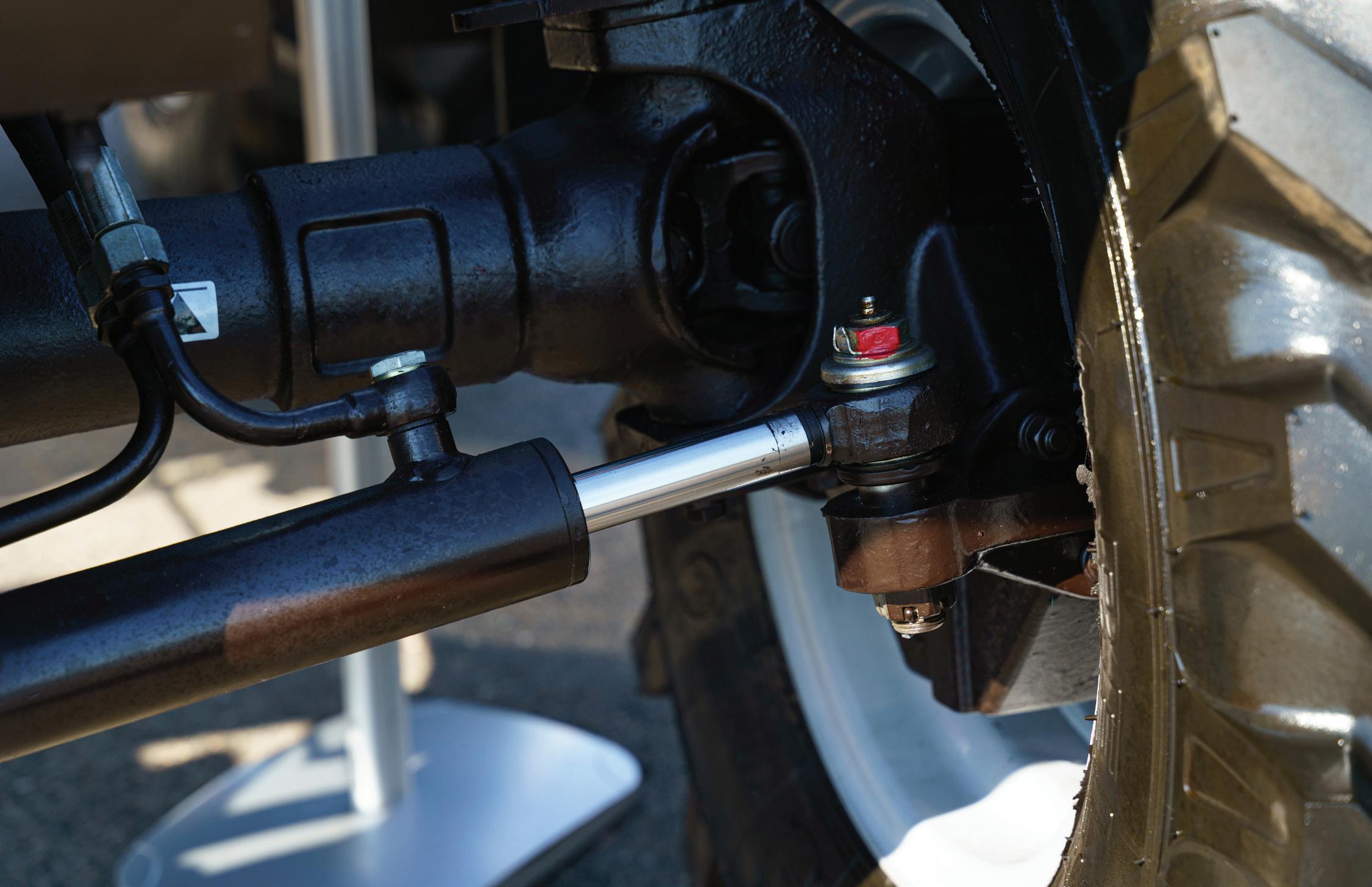
As we’ve written about previously, Husco positions its GenSteer system as a fundamental shift in how steering safety is approached on mobile machines. Traditional “road-safe” steer-by-wire systems typically retain a physical link — mechanical or hydraulic — between the operator and the steering axle. While familiar and commonplace, that linkage introduces complexity and additional failure points.
GenSteer takes a different approach by eliminating that dependency and instead uses operator-generated input as the basis for maintaining control, even in fault conditions. The goal is continuous steerability without relying on layered redundancy such as backup batteries or duplicate controllers. In this architecture, safety is not an added subsystem but an inherent characteristic of how steering force is generated and transmitted.
Equally important is how the system supports automation. By decoupling steering from mechanical constraints, GenSteer creates a platform that can be more easily integrated into automated machine architectures. The steering system effectively becomes “plug-in ready” for higher levels of control, allowing OEMs to layer in autonomous or semi-autonomous functions without redesigning the core steering hardware.
“Steer-by-wire has existed for decades. Aerospace is really what drove it. When you needed superhuman powers to handle driving a fighter jet or an Airbus 380, and you needed to be able to concentrate for hours at a time, you need automation,” said Ben Holter, Product Director, Mechatronics, HUSCO. “You need an ability to drive unstable machines. The solution for steer-by-wire has long been accepted in the aerospace industry. We were able to do things never thought possible. We can design a machine that's inherently unstable and let the soft-
ware help the operator make it better.”
This shift also enables software-defined steering behavior. Machines can dynamically adjust steering response based on the task — faster, more aggressive turning during repetitive loading cycles, for example, and slower, more precise control in confined spaces. In agricultural applications, that same flexibility allows high-speed steering in open fields and finer control when operating in tighter environments such as sheds or yards.
Bosch Rexroth and HydraForce extend the steer-by-wire conversation through valve technology and integrated steering blocks designed for both automated and hybrid control modes.
Direct-acting valves play a key role in this transition. Compared to pilot-operated designs, they respond faster and more predictably, bringing an advantage when steer-
ing inputs are generated by software rather than a human operator. They also can handle larger amounts of flow, said Ross Johannes, Application Tech Services Team Leader, HydraForce.
“With the direct operator, you have a much faster valve than you would have with a pilot operated valve. With automated functions like steering, the direct acting can provide some advantages there,” Johannes said. “Computers controlling steering can change direction very fast. This valve gives you a better ability to keep up with that.”
Pre-compensated valve designs further align with steering requirements, particularly in auto-steer and guidance applications where flow demands and response times must remain consistent. In these scenarios, traditional pilot-operated valves can struggle to keep up with rapid switching, while direct-acting solutions provide more stable performance.
At the system level, integrated steer-
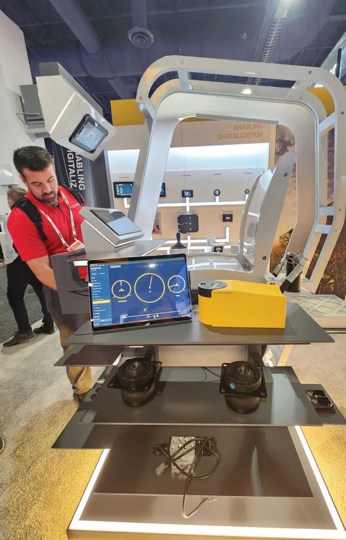
PARKER HANNIFIN'S MODEL SHOWED HOW ITS ARMREST JOYSTICK AND CONTROLLERS WORK TOGETHER TO GIVE OPERATORS A MORE NATURAL HYDRAULIC FEEL AND UNDERSTAND HOW THE SYSTEM IS OPERATING.
ing blocks demonstrate how steer-by-wire can coexist with conventional architectures. These assemblies support parallel steering paths versus pure steer-by-wire, Ross said. For example, on an ag vehicle, you can steer with the wheel but may need to put your machine into auto guidance when row harvesting. “You have two steering axes, but this valve with the sensor would essentially block off the electronic steering circuit and verify that it's blocked off. It can be dangerous if you ever have a contamination issue and your electronic steering valve is stuck open or broken for some other reason. You could end up with uncommanded movement or going the wrong way,” Ross said. “What this valve enables us to do is to shut off the electronic steering circuit, and then provide feedback on the valve to verify that it is closed. Having these types of sensors on cartridge valves really allows us to put that system diagnostics in any circuit that we want.”


Hydac offers a similar concept, said Christopher Kolbe, Senior Vice President of Sales and Marketing at HYDAC Technology Corp. He highlighted a hydraulic valve that is driven electrically with an electric motor.
“You have a sensor that tells you exactly where it is. From a functional safety standpoint, it knows exactly where it is, and from an accuracy standpoint, there's zero hysteresis,” he said. “If the engine’s off, I can still operate this. If, some reason you must lower something, you can still actuate it without any hydraulic power.”
Steering does not evolve in isolation. At Rexroth, it is part of a larger shift toward software-defined machine control built on electronic joysticks, sensors and electronically controlled pumps.
The emphasis is on “control authority” — the ability to measure, command and consistently return a machine to a desired state. That capability underpins a growing range of operator-assist features, from automated digging cycles to guided machine movements.
“We're setting the foundation stones for next generation technology, which is really all about the software. And then integrating all solutions, such as hydrostatic
drives, motors and controls,” said Terry Hershberger, Mobile Hydraulics Technology Leader for Bosch Rexroth. “We’ve always talked about drive and control. Today it's even extended beyond drive and control, because it's software and the ability to measure, monitor and see.”
Hershberger noted that Rexroth’s software packages are designed to take a specific application, and especially ones with semi-automation, and make it simpler to use. For example, an excavator operator can make perfect lines due to the kinematics and software and hardware packages that ensure higher efficiency, lower engine speed, and higher control authority. Rexroth orients its solutions to the specific needs of the specific application.
“We're providing the hardware and software, so we are involved with every aspect of the operation of that machine,” Hershberger said.
Across the industry, suppliers emphasize that hydraulics remain central even as machines become more autonomous. Hydraulic systems continue to provide the force and motion, while electronics and software define how that power is applied.
Garrett Bialosky, Global Mobile Systems, Industry Market Manager at Parker Hanni-
fin, noted that Parker sees the growing role of closed-loop control, where pressure and flow data are continuously monitored to maintain safe and efficient operation. These same feedback systems support automated steering and broader machine functions, enabling everything from user-assist features to higher levels of autonomy.
“Different customers are looking to get the most out of their machines, with autonomous control and safety control,” Bialosky said. “You're always going to need those hydraulics, which Parker has, because that creates all your force and movement. But you want to start capturing through electronics, how everything's performing, the pressures, the loads. There you take it into your controllers, and you use closedloop control. You keep things in safe operation, autonomous control.”
Bialosky pointed to Parker’s TFD tactile feedback device as an entry into steerby-wire paired with functional safety control. The armrest joystick allows you to feel different types of haptic feedback. He said that operators still like the hydraulic feel, so this provides electronic feedback that feels more like a natural hydraulic joystick. It also allows automatic return to center, where it pushes the wheels back inline.
Danfoss added that many manufacturers expect a complete system, with an electric motor that partners with hydraulic systems. This is why eSolutions are so important to Danfoss, said Joe Budden, eHydraulics Portfolio Manager at Danfoss Editron. This transition to electrohydraulic systems is now focused on automation and operator-assist capabilities.
Software development is becoming a key differentiator in this phase, with increasing use of advanced tools like Danfoss’ Plus+1 software product, to accelerate development cycles. At the same time, electrification efforts, such as electric pumps and traction systems, are being designed with integrated control architectures in mind. Steering, in this context, is expected to function as part of a unified, softwareready platform rather than a standalone subsystem.
“If our customers want to come to us and say, we just want to buy a pump from you,
we're happy to sell them a pump. But putting them together with a little bit of software, you're gaining additional controllability, additional efficiency, and getting additional productivity out of the machine by doing it,” Budden said.
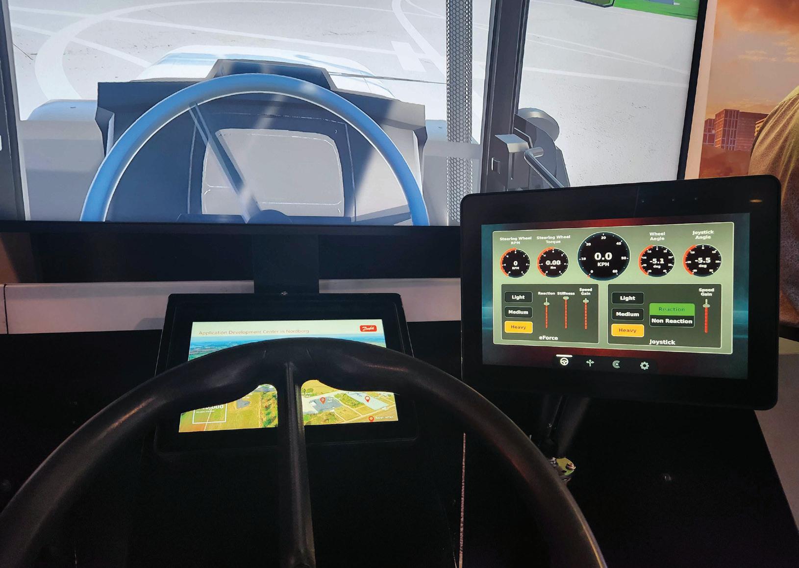
Danfoss showed where its current and newly released technologies can be used on an excavator model in hydraulics, e-hydrau lics, electrification, digitalization, autonomy, and software through the subsystems common to construction machinery: propel, steer, work, and control. For steering, however, they offered a demonstration of a new electric steering unit which will be launched later this year. It ties directly to the steering wheel and can also connect to Danfoss' electrohydraulic steering unit down below. The machine can be driven via steering wheel or joystick, and features easily changeable settings from light to heavy load for operator comfort and experience.
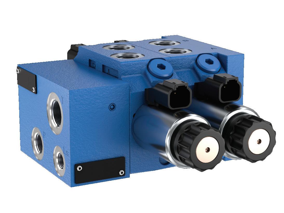
the best feel for that type of machine. With both electrohydraulic and hydraulic, we always want to continue moving those all forward."
"Operator, comfort and feeling throughout the day is really important. We need to ask, what is the machine that we are working with? How do we give that best feel to the customer? That's one of the key that's driving our innovation in the steering units today," said Ricky Anderson, Steering Sales Manager -Americas at Danfoss Power Solutions. "And we do the same thing with our standard steering units. We try to optimize
Hydac’s Kolbe agreed about the need for holistic system development. “When you’re talking about user assisted functionality and autonomy, one of the key elements is steer-bywire or brake-by-wire. The problem is, is if you buy the hydraulic hardware from somebody, the electrical hardware from somebody, and the sensor and controller, you then must certify all those parts together. What we do is we have controllers, sensors and a valve system that's all functional safety rated for that,” Kolbe said. “We're able to do joystick steer, steer-by-wire, and brake-by-wire, which enables our customers then to go to remote control, autonomy or user assist function.” FPW


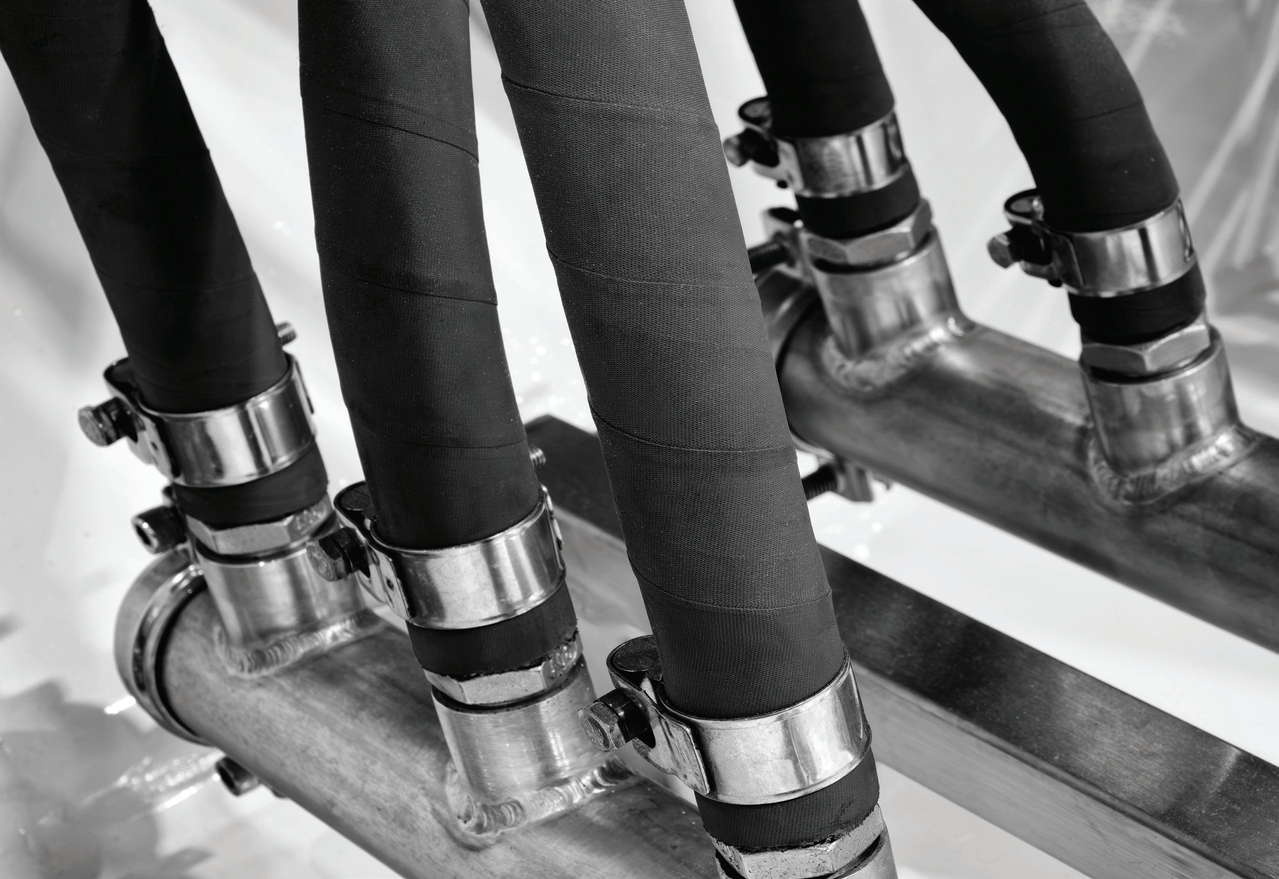
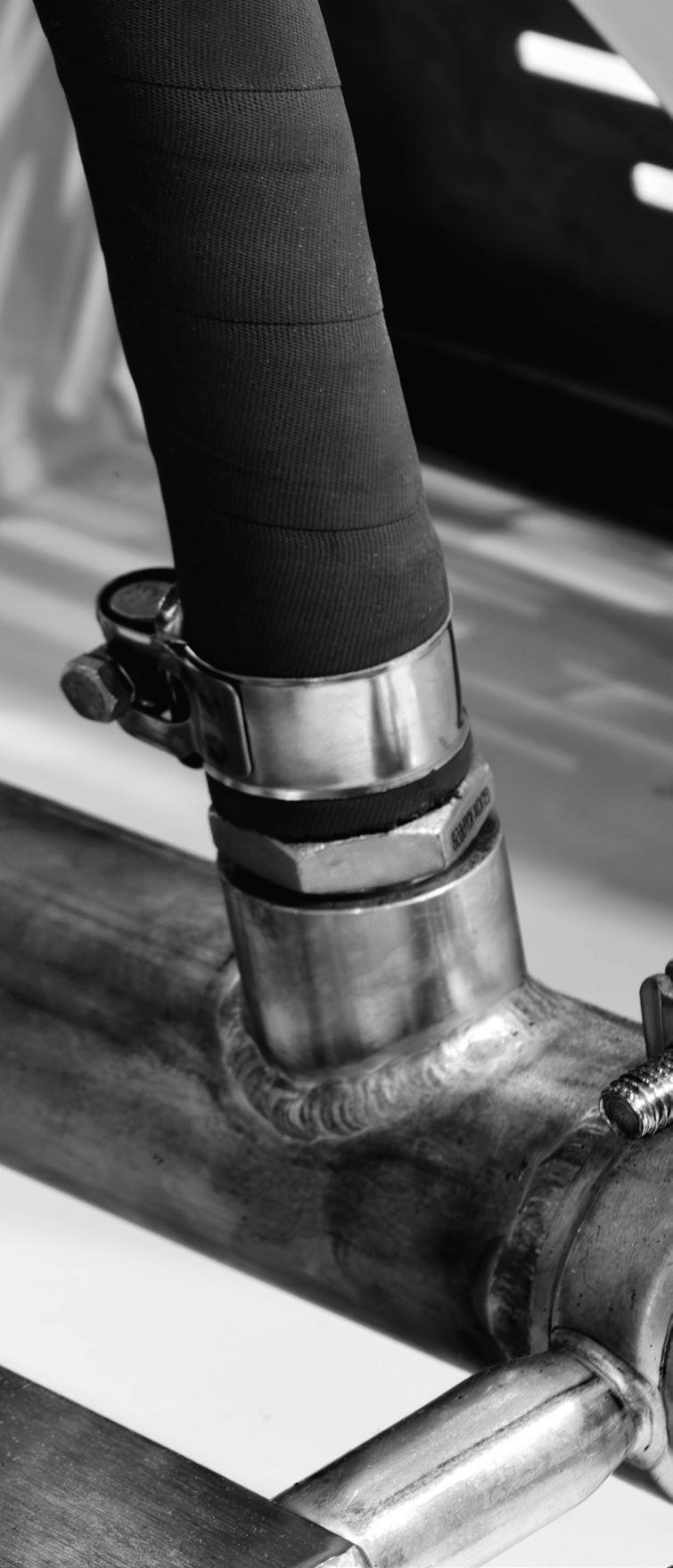
HYDRAULIC HOSE ASSEMBLIES are critical components in fluid power systems, responsible for transferring pressurized fluid as a force transfer method to and from components such as pumps, cylinders, valves, and motors. Understanding the fundamentals of hydraulic hose is essential for ensuring system reliability, efficiency, and safety in both industrial and mobile hydraulic applications.
A hydraulic hose must be designed to handle high-pressure fluid without leaking while also remaining flexible enough to accommodate movement between two points. Unlike rigid tubing or piping, hydraulic hose allows bending, flexing, and a very small degree of twisting. Constructed of a rubber inner tube, steel or
textile reinforcements in braided or spiralwound patterns, and, finally, a protective synthetic rubber cover, hydraulic hose is perfectly suited for its task.
The inner tube is typically made from synthetic rubber, such as Buna-Nitrile, but thermoplastic or PTFE can be used for specific applications. Hydraulic hose material dictates how well it resists chemical breakdown from oils, fuels, and other fluids. Material choice also depends on the type of fluid used, as exotic fluids may require the aforementioned PTFE or even Viton.
The application's temperature range also matters for hose selection, especially when ambient heat is extreme (damaging internal heat is less common, as it can destroy the fluid itself). Appropriate chemical and thermal compatibility is critical to
prevent material breakdown, which could lead to catastrophic hose failure.
Surrounding the inner tube is the reinforcement layer, which provides the hose with strength and contributes to its pressure rating. Reinforcement can consist of one or multiple layers of braided wire, spiral wire, textile, or synthetic fiber. Wirereinforced hoses are required in high-pressure applications, with 2-, 4-, or 6-wire spiral designs offering higher pressure capacity and excellent fatigue resistance. However, braided hose offers the highest flexibility with only marginal sacrifice in pressure capacity.
Textile-reinforced hoses are suited for lower-pressure hydraulic circuits where flexibility and cost-effectiveness are priorities, as well as for non-conductive appli-
Learn some quick basics to hose assemblies and read about the latest innovations with these critical hydraulic system components.
By Josh Cosford, Contributing Editor and Mary C. Gannon, Editor-in-Chief
cations in and around electrical wires.
Hydraulic hose is rated for working, fatigue, and burst pressure; each of which is double the previous (for example, burst pressure should be four times working pressure). Working and burst pressure are self-explanatory, but know that fatigue pressure is the minimum pressure at which permanent damage occurs.
The outer cover serves as a protective barrier against abrasion, heat, ozone, and environmental fallout in heavy manufacturing. Materials such as neoprene, polyurethane, or PVC provide durability across various operating conditions. Some hoses are designed with extra abrasion resistance for applications where dragging a hose across
the ground or floor is unavoidable.
Hydraulic hose selection is based on standard criteria: operating pressure, flow rate, temperature range, fluid compatibility, bend radius, and hose ends. Working pressure is labeled on the lay line markings of the hose, and flow rate is dictated by internal diameter. Temperature ratings account for both the fluid temperature and ambient conditions, as extremes can weaken the hose or degrade its materials. The hose's bend radius must also be observed to prevent kinking, which can reduce flow or damage the reinforcement layer.
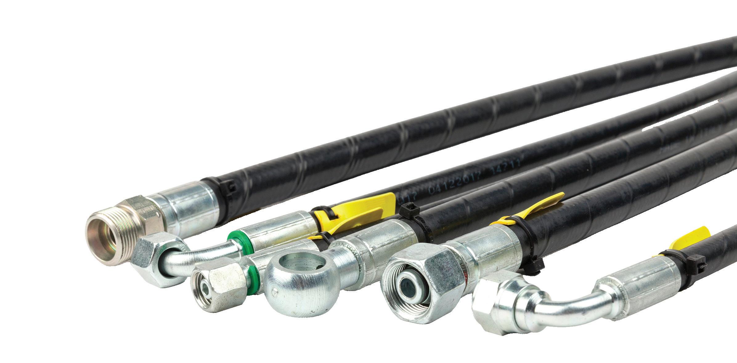
Hose couplings are available in onepiece and two-piece configurations, but it’s important to remember that they must match the hose type and crimp settings specified by the manufacturer. Non-factory
ends can cause failure by over-crimping and subsequently damaging the reinforcement, or under-crimping and risking those hose ends coming loose or popping off.
Despite their commodity-level reputation, hydraulic hoses are sophisticated components designed to transport pressurized fluid safely and efficiently. Knowledge of their construction, pressure capabilities, material compatibility, and installation requirements is essential for maintaining reliable hydraulic systems. By selecting the correct hose for a given application and following proper maintenance practices, operators can minimize downtime, enhance system performance, and ensure operational safety. FPW
ASSEMBLY FUNDAMENTALS, we’ll look at some newer technologies available in the market. From the hose itself to the protective covers, crimpers to fittings, these components all must work together seamlessly to create a safe and long-lasting design. Read on for some of the latest hose components launched in the last several months.
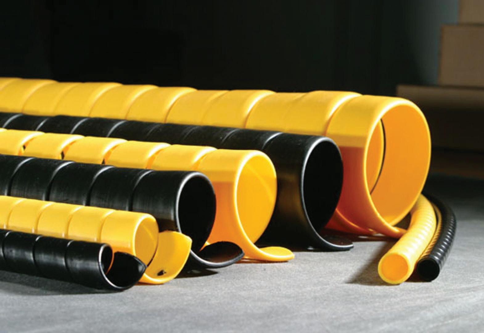
Material performance is critical in hose protection sleeves and covers. This is why Caplugs manufactures spiral wraps using polyester, which the company says provides advantages compared with the nylon materials commonly used in the industry. While nylon remains widely adopted, often due to long-standing specification practices, newer materials can offer improved durability and protection. These ready-to-install materials can provide higher protection and longer service life.
At CONEXPO, the company emphasized that hose protection products serve multiple roles. Protective sleeves are often used to improve safety by guiding hydraulic fluid away from operators in the event of a hose burst. Spiral wraps, by contrast, primarily protect hoses from external damage such as abrasion, punctures and impacts, conditions frequently encountered in demanding environments such as forestry and construction equipment.
Customization options are also expanding. Caplugs offers polyester printing in Buffalo and laser-etching capabilities in Finland for its hose protection products, enabling customers to add identification markings or branding directly onto spiral wraps or related components. Color coding can also be used to identify different hydraulic lines or circuits within complex machinery. Caplugs caplugs.com
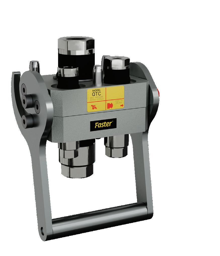
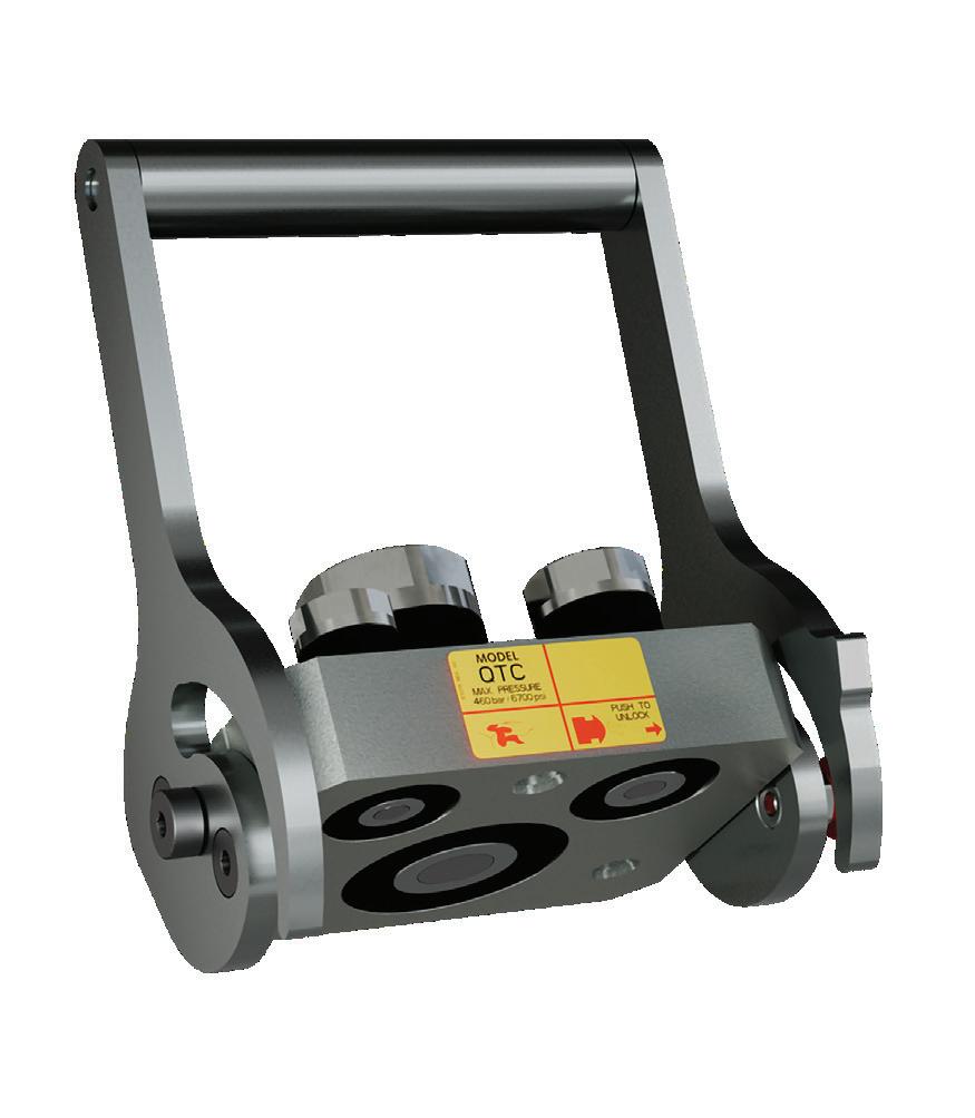
The MultiQTC series multiconnection system is specifically engineered for large-scale excavators and demolition excavators (20 to 50-ton class). This system allows for rapid attachment changeover at a fraction of the cost of fully automated "in-cab" systems, without complex maintenance.
It handles more than 50% higher flow capacity at equivalent pressure drop compared to conventional connection interfaces, supporting heavy-duty attachments such as hydraulic shears, large concrete crushers and hydraulic hammers. It features dual-hand coupling control, with an auxiliary locking system on the fixed side that allows precise, stable handling of the mobile unit during connections. Integrated technology prevents hydraulic fluid leaks during connection, reducing environmental impact and replenishment costs.
Finally, the system simplifies repetitive, strenuous tasks, transforming site work into a more sustainable and less fatiguing activity for improved operator comfort. Additionally, its ease of use encourages operators to always select the most suitable tool for each work phase, reducing component wear and fuel consumption. Faster fastercouplings.com
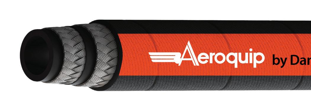
Aeroquip by Danfoss GH888 main pump hose is a two-wire braided hydraulic hose designed for the main pump line on tractors. It can be used in place of four-wire spiral, offering greater flexibility, reduced weight, increased heat resistance, and lower total cost of ownership.
GH888 hose features a novel composite inner tube with increased stability that enhances its robustness and boosts its pressure capability. It operates at pressures of up to 350 bar for size 12 (3/4-in.) and 300 bar for size 16 (1-in.). Such pressure ratings have traditionally required four-wire spiral hose conforming to EN856 4SP or SAE 100 R12/R13.
With up to 24% improved force to bend compared to four-wire spiral hoses, GH888 Hose facilitates easier installation in cramped engine compartments, granting engineers greater freedom in system design and hose routing. This increased flexibility also translates to ergonomic benefits for assembly technicians, enhancing occupational safety and reducing physical strain during installation. The up to 15% lower weight of GH888 hose, compared to four-wire spiral hose, contributes to overall machine weight reduction goals, leading to improved fuel efficiency and minimized soil compaction. Danfoss Power Solutions danfoss.com
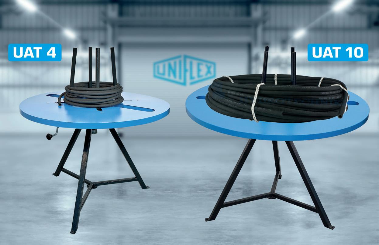
With the UAT 4 and UAT 10 winding stations, Uniflex supports workshops and production facilities in the controlled winding and unwinding of hydraulic hoses. The stations streamline workflows in hose processing, shipping, and precise cutting.
The UAT 4 is designed for hydraulic hoses up to 1 ½ in. in diameter and 40 m in length, with a total diameter of 1,200 mm and a load capacity of 80 kg. The larger UAT 10 has a diameter of 1,500 mm and can handle hoses up to 2 in. R13. Both models can be quickly and tool-free adjusted to different hose sizes. Their easy operation ensures smooth, time-saving workflows in workshops and production environments.
A practical feature is the integrated table recess: entire hose bundles can be comfortably placed or picked up using a lifting strap or lifting hook.
UNIFLEX Hydraulik GmbH uniflex.de
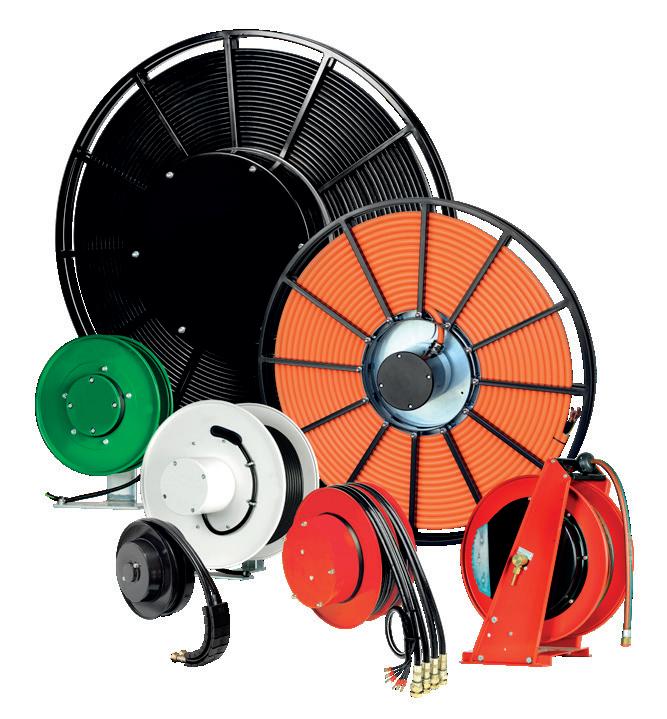
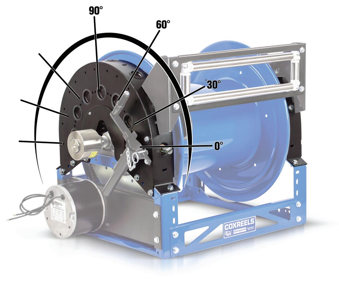
The 1600 series from Coxreels is a reeling platform featuring a versatile symmetric reel design, with an extensive array of components and configurations to meet the demands of any conceivable application.
Central to this adaptability is the Universal Bracket Kit. Constructed from heavy-duty, 12-gauge powder-coated steel, the bracket serves as a dual-purpose chain and gear guard. It provides four distinct payout angles (0, 30, 60, and 90) for mounting rewind cranks, three- or four-way roller guides, and three-way pins on either side of the reel. For added maintenance efficiency, the kit includes a removable center guard cap for quick bearing access. Coxreels www.coxreels.com




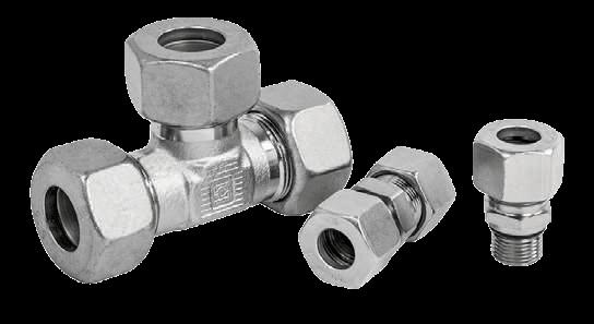
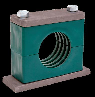

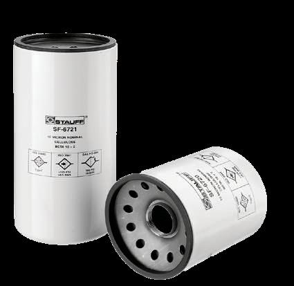
From the original STAUFF Pipe Clamps to our Metric Tube Fittings and Quick Release Couplings STAUFF offers port-to-port hydraulic solutions, components, and accessories for hydraulic systems and applications.
STAUFF is your trusted source for industrial and mobile fluid power components and solutions worldwide.