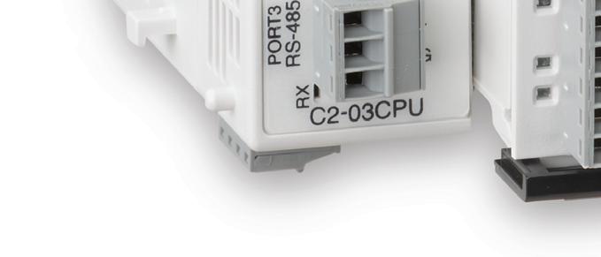
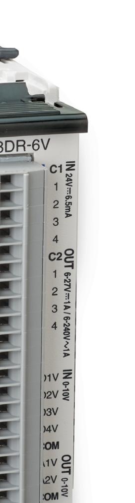
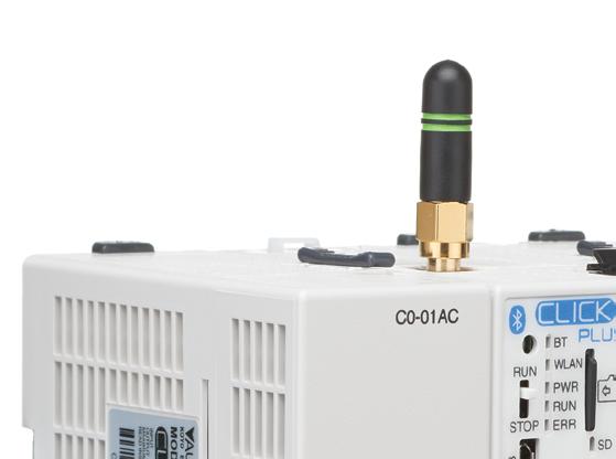
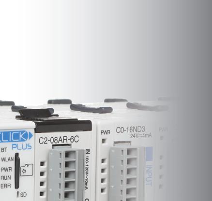
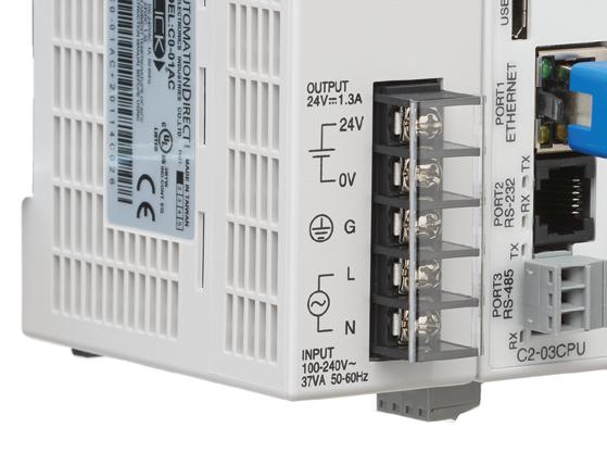
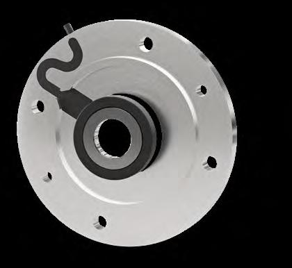
CLICK PLUS PLCs provide the same simple, practical control the CLICK PLC line is known for but with some surprising bells and whistles. Data logging, Wi-Fi connectivity, MQTT communication, and increased security measures are just a few of the impressive features offered with the CLICK PLUS PLC series.
Using the same FREE streamlined PLC programming software as its predecessor, CLICK PLUS PLCs provide straightforward, no-learning-curve programming. Combine that with a starting at price of just $110.00 and the CLICK PLUS PLC is undoubtedly the unmatched value leader!
Built-in Option Module Slot
For custom stand-alone PLC I/O con gurations that exactly match your application (option module sold separately).
Use any CPU with option module(s) as a complete PLC for small systems or expand the I/O with stackable I/O modules for larger applications.
Detroit’s manufacturing renaissance
About 15 years ago, a well-loved local comedian here in Cleveland put together a couple of spoofs called “Hastily made Cleveland tourism videos” which made the rounds and gave us all a good laugh at ourselves. But unfortunately, as happens with the Internet, they were soon shared near and wide, and became a sensation for a bit, each garnering more than 10 million views in places far from Cleveland. As a rough comparison, it’s one thing when you joke about your family with your family, but it hits different when someone else starts doing it.
The videos weren’t an accurate depiction of the city, for sure. They focused on depressing shots of abandoned buildings, people in downtown who let’s say weren’t the most photogenic citizens, and sad industrial images that could be captured in most any American city. But the punchline at the end resonated with many locals who feel a sense of competition with other rust belt cities. The second video wrapped up with, “It could be worse though — at least we’re not Detroit!”
Fast forward to today, and Detroit (like Cleveland, Pittsburgh, and others) is not the punchline that it once was. The city still has its challenges, but signs of rebirth are showing up in many places.
I’ve driven past the hulking 18-story Beaux-Arts Michigan Central Station countless times over the years when driving into or through Detroit. It always amazed and saddened me to witness its level of decay. You could see right through its windowless upper stories,
and I wondered how long it would be before the building was razed.
Thankfully, that didn’t happen, and I’ve heard over the last few years about how Ford had purchased the structure, an old train station, and was redeveloping it into some sort of innovation campus. This Spring, I received an invite to visit that new initiative through one of its main tenants, Newlab Detroit.
For Newlab, this is its second main outpost after Brooklyn. Its focus on bringing together manufacturing partners, local government, venture capital investors, and innovative startups is the kind of mashup that’s needed in America’s heartland. Manufacturing has ebbed and waned in this country, and after a generation of offshoring, bringing it back in force requires new ways of thinking and different ways of partnering together. Please read my story on Newlab, starting on page 28, to learn more about how it’s working out for its participants. I was pleasantly surprised, and I think you will be, too.
Here’s hoping that my hometown can aspire to be more like Detroit — and bring creativity and innovation in manufacturing to the forefront once again. DW
Paul J. Heney • VP, Editorial Director pheney@wtwhmedia.com
Connect with me: linkedin.com/in/paulheney
Solutions Under Pressure
MANUFACTURING
NewLab Detroit provides a blueprint for the future of manufacturing
Newlab Detroit provides a blueprint for the future of manufacturing by fostering a collaborative ecosystem of startups, venture investment, and corporate partnerships.
Digital integration of motion systems
Industry experts discuss how motion systems are becoming the backbone of manufacturing’s shift toward fully integrated digital ecosystems.
Heavy duty electric actuation to replace hydraulics
Following our look at linear components for presses, we examine the specific requirements for implementing electromechanical actuation on heavy-duty machine tool axes.
What your motors are really costing you
Many manufacturing inefficiencies start at the design stage, but are uncovered on the shop floor. This special section offers engineers a refresher on design for manufacturability (DFM), from its origins and core principles to the mindset and digital tools that define modern practice.
David Strain of Technidrive explains how to accurately calculate electric motor running costs and leverage those insights to boost industrial energy efficiency.
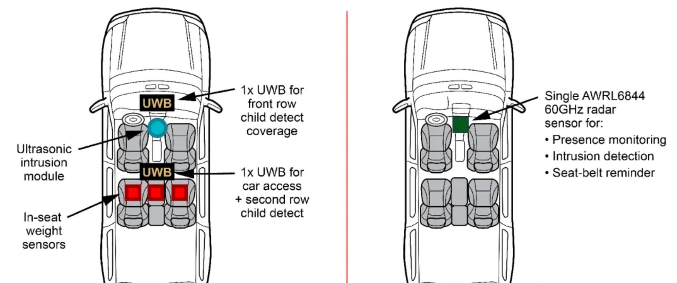
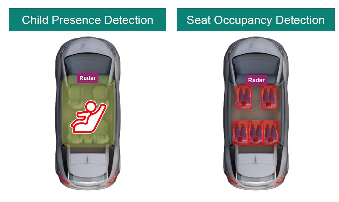
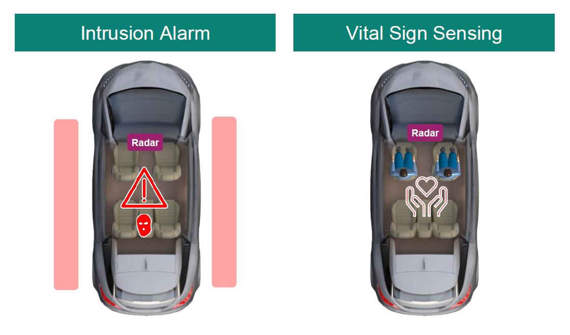
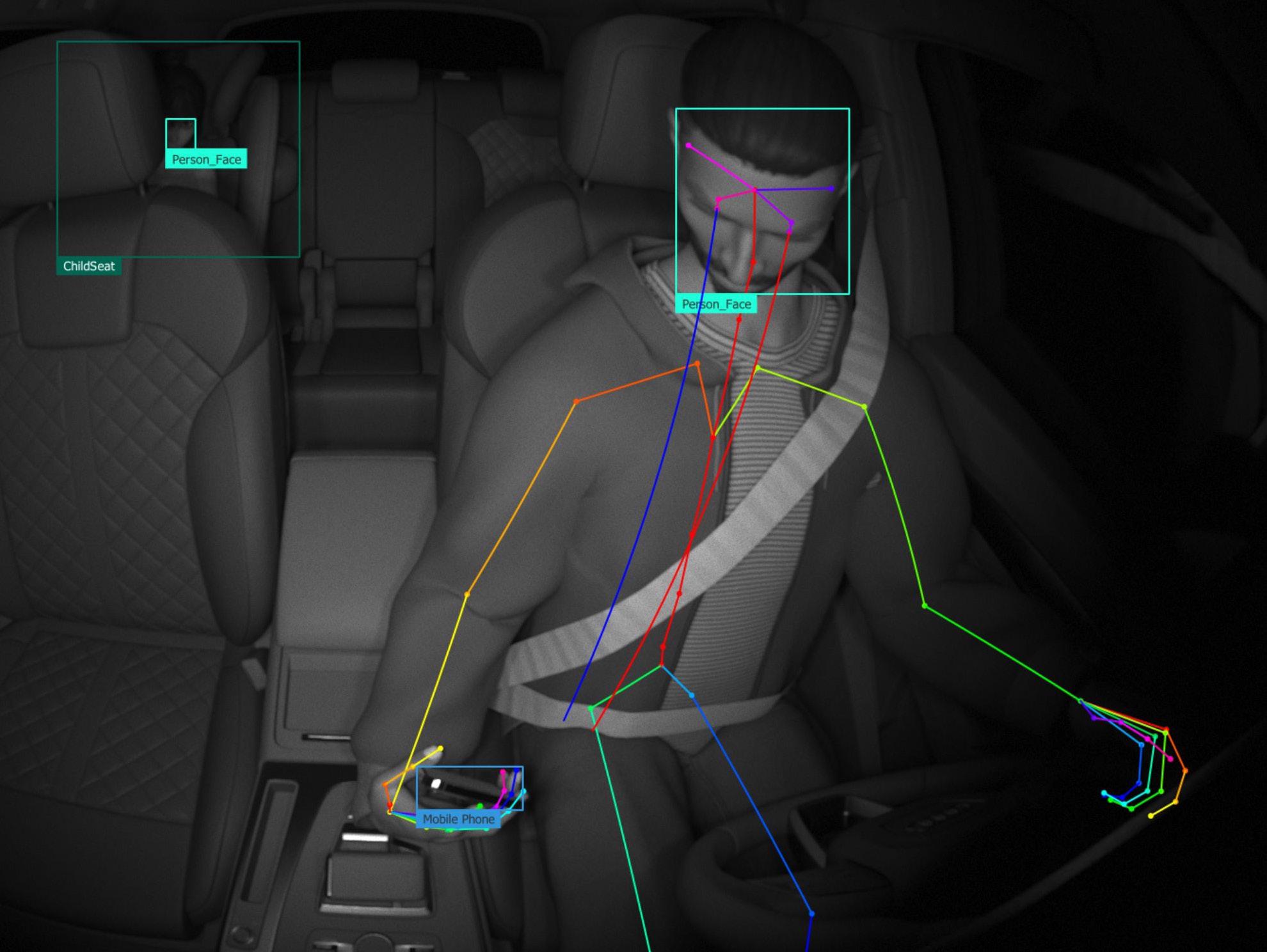
How is radar used for automotive in-cabin sensing?
We explore how millimeter-wave radar sensors enable advanced interior monitoring, from child presence detection to vital sign tracking.
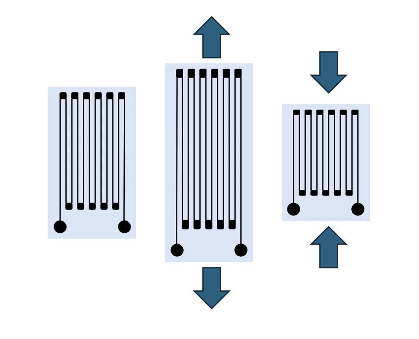
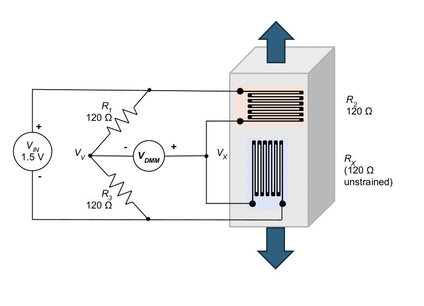
Defining and measuring strain
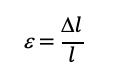
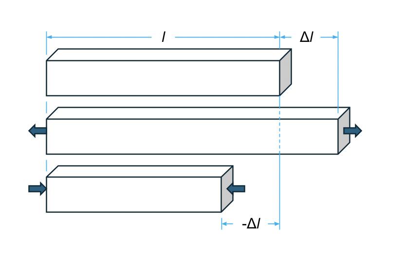
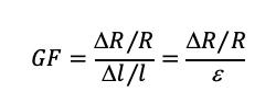
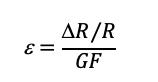
A metallic foil strain gauge can detect how a test specimen responds when subjected to axial stress.
INFORMED. SMART. AHEAD. Stay
Design World reports on the vast world of design engineering and machine building with technical, indepth content. We cover semiconductor, medical, factory automation, packaging, off-highway, material handling, simulation, rapid prototyping, and more. By signing up for the Engineer’s Edge, you’ll stay on top of the news and trends happening in the engineering space. Scan the QR code to access three weekly newsletters plus new product announcements!
EDITORIAL
VP, Editorial Director Paul J. Heney pheney@arrowfly.com
Digital Production Specialist Elise Ondak eondak@arrowfly.com
WEB DEVELOPMENT
Web Development Manager B. David Miyares
Digital hydraulics cut power consumption by 35%
EDITED BY MARY GANNON EDITOR-IN-CHIEF FLUID POWER WORLD
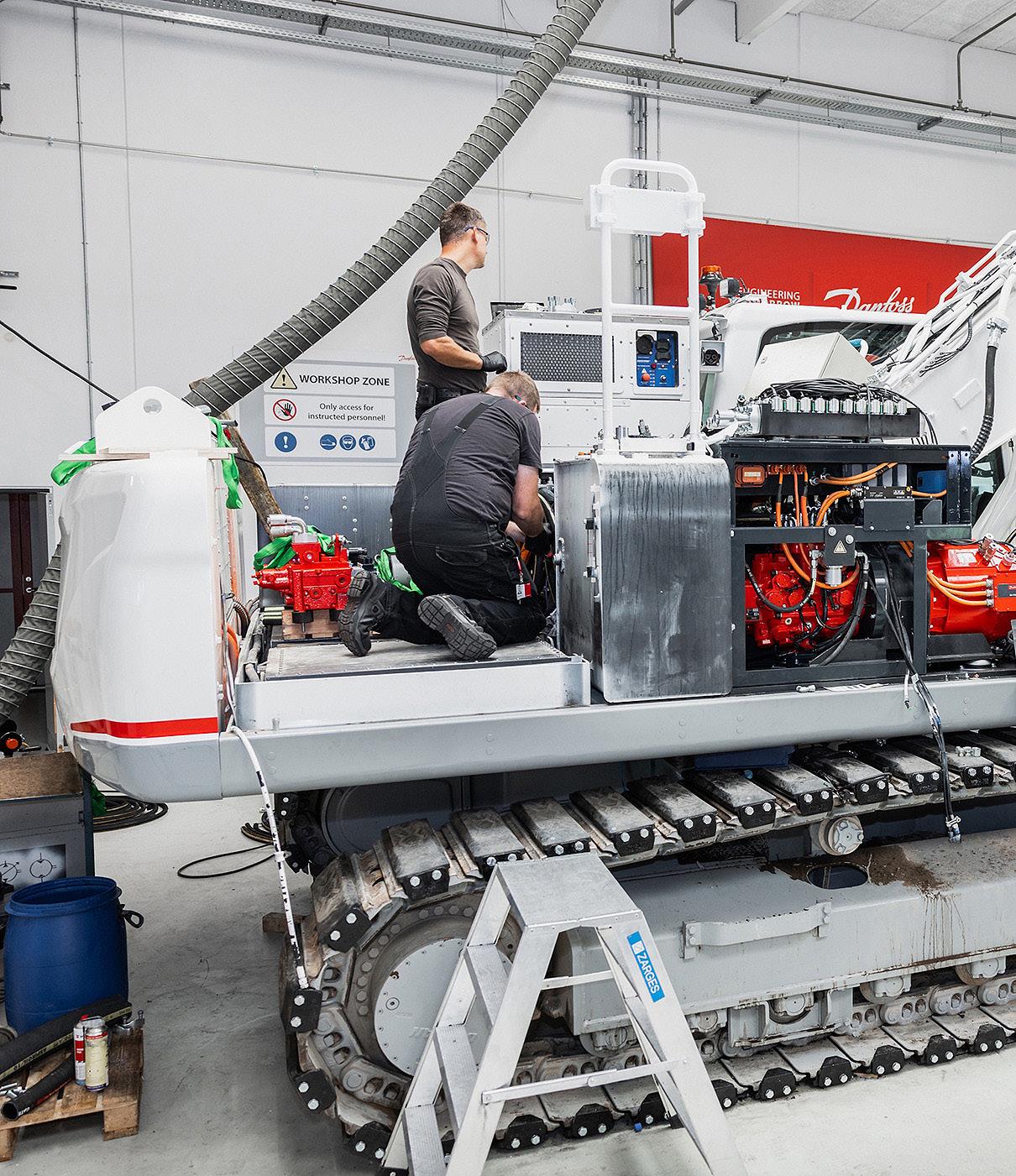
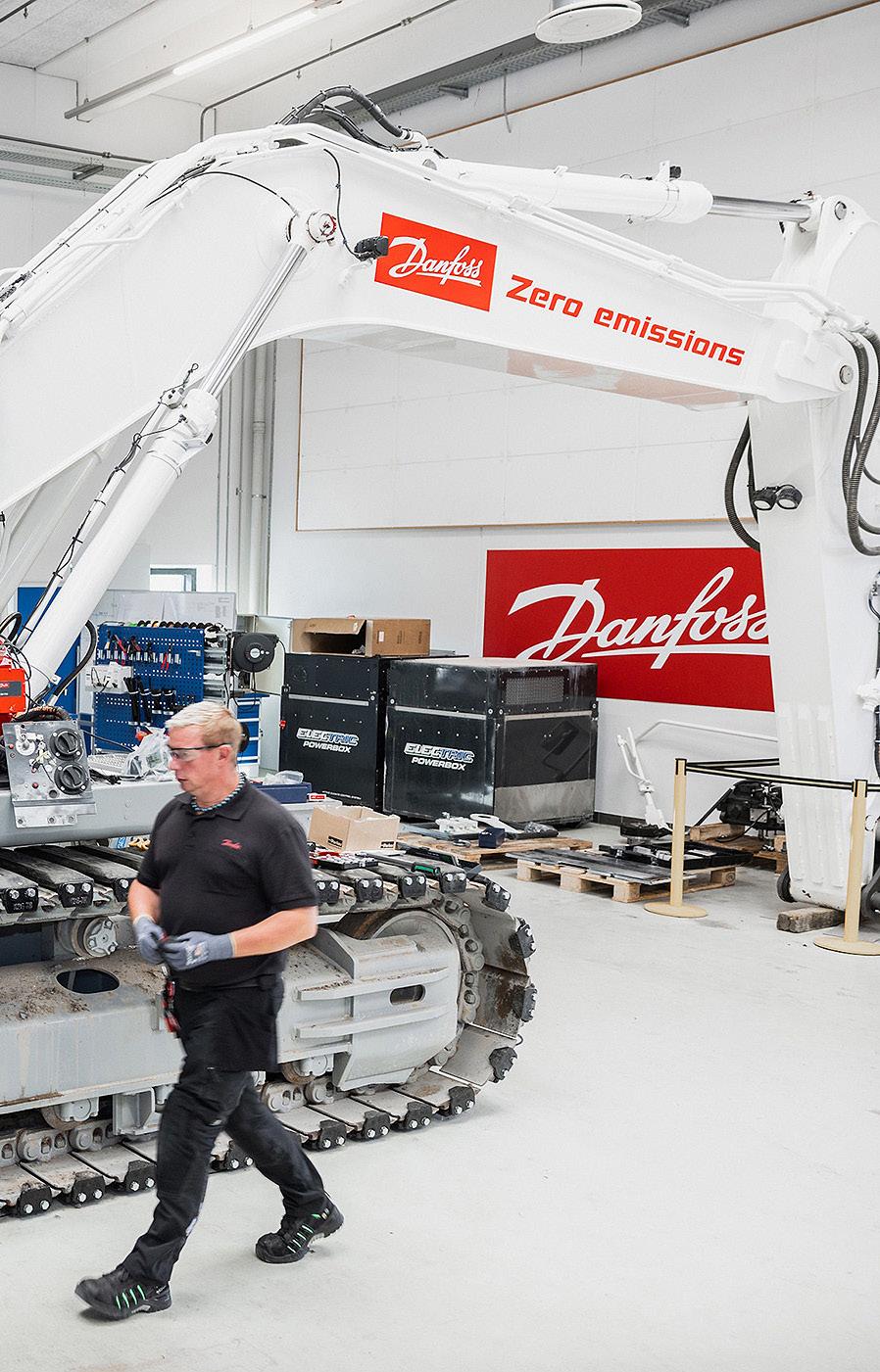
As it wrapped up the initial project testing phase, Danfoss Scotland, part of Danfoss Power Solutions, announced the results of its Dextreme Max system validation in a 30-ton battery-electric excavator. Undertaken with a £4.29 million grant from the UK Government, Danfoss demonstrated that its Dextreme digital hydraulic architecture reduced excavator power consumption by 35% across a representative duty cycle mix, corresponding to 53% longer runtime on a single charge. The results confirm the potential of the Dextreme Max system to significantly increase energy efficiency and accelerate the electrification of large excavators.
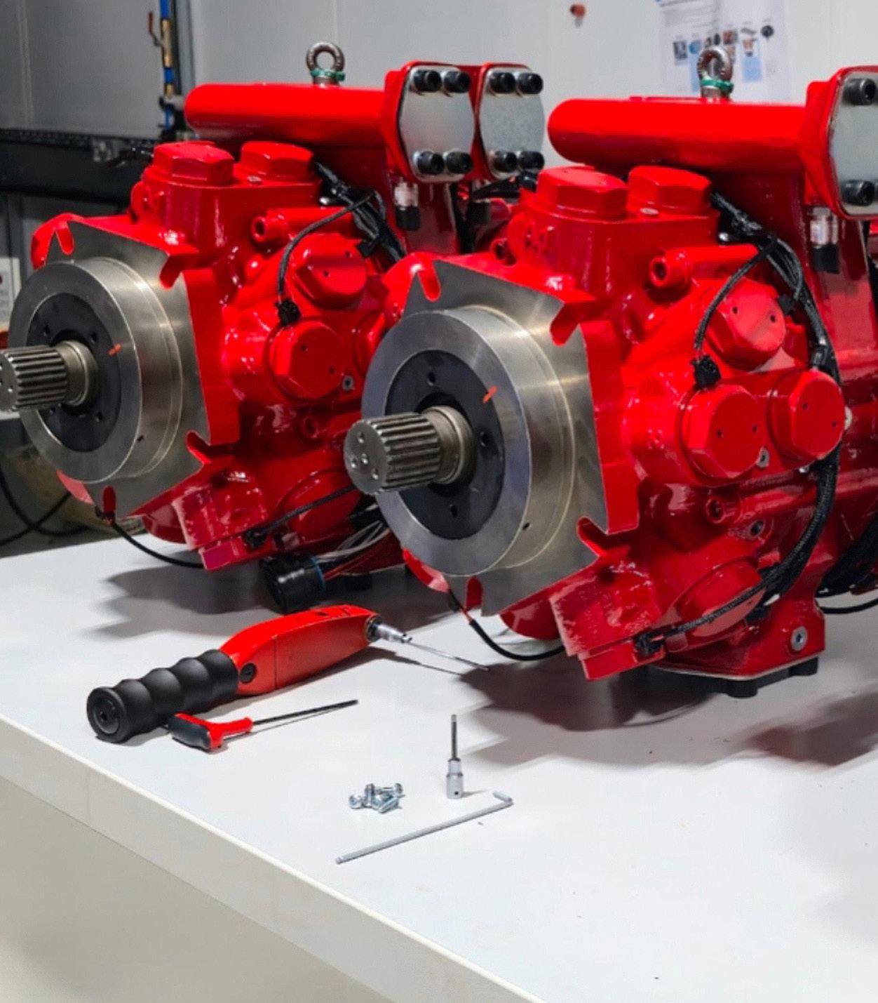
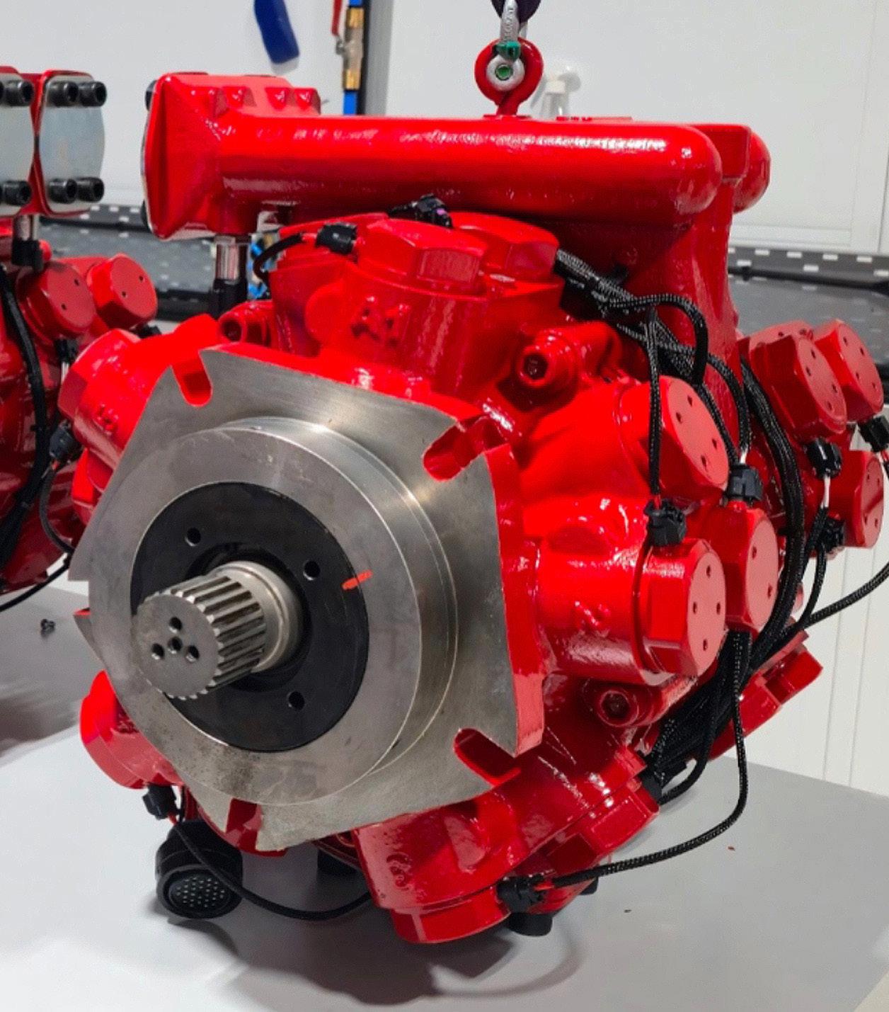
The system aims to cut excavator energy consumption by up to 50% by reducing energy losses and recovering energy that would otherwise be wasted. The system’s integral component is the DDP180D, a digital displacement hydraulic pump/motor with multiple independently controlled outlets. The Dextreme Max system provides independent actuator supply, eliminates flow-sharing losses, and enables energy recovery from excavator motions such as boom lowering.
When asked what’s next for the project, Matteo Pellegri, senior manager
of Engineering, Digital Displacement Systems, said that the next phase is already taking shape.
“This project taught us a great deal: the system’s shortcomings, areas for improvement, and the broader potential we can now pursue with a clearer focus on productization and simplification. We’re not going back to the drawing board. The technology is mature and requires refinement rather than a fresh start. The pump hardware is nearly
perfect — it’s incredibly efficient — so optimization will focus on software control and the system that surrounds the pump,” said Pellegri. “Digital displacement is at the forefront of fluid power, and that remains our focus. Some elements of the system came from our existing portfolio outside of excavator-specific applications, and they performed impressively from day one. That speaks to the quality and versatility of what we bring to non-standard
POWER TRANSMISSION RETAINING DEVICES & maintenance & assembly tools
Danfoss Scotland personnel work on converting the Develon DX300LC‑7 crawler excavator to the Dextreme Max system. Danfoss
Materials of: CARBON, ALLOY and HARDENED ALLOY STEELS
Materials of: AL UMINUM and CORROSION RESISTANT STEEL applications. There is always room to push further, and we intend to.”
In 2023, Danfoss received a grant from the Red Diesel Replacement Phase 2 Competition, a program funded through the Department for Energy Security and Net Zero’s £1 billion Net Zero Innovation Portfolio, to develop and
WHITTET-HIGGINS manufactures quality oriented, stocks abundantly and delivers quickly the best quality and largest array of adjustable, heavy thrust bearing, and torque load carrying retaining devices for bearing, power transmission and other industrial assemblies; and specialized tools for their careful assembly.
Visit our website–whittet-higgins.com–to peruse the many possibilities to improve your assemblies. Much technical detail delineated as well as 2D and 3D CAD models for engineering assistance. Call your local or a good distributor.
BEARLOK SHOELOK BEARLOK Shrink Disc
BEARHUG
Design For Industry
validate the Dextreme Max system. The program provided funding for projects developing low-carbon alternatives to red diesel for the construction, mining, and quarrying sectors. Danfoss used the funding to procure a battery-electric excavator and integrate its Dextreme Max system into the machine. The grant represented approximately 65% of the eligible project costs, with Danfoss funding the remaining portion.
Danfoss selected a Develon DX300LC-7 crawler excavator for the project. Originally diesel-powered, the excavator was supplied in an electric configuration by Staad B.V., which replaced the engine with an electric drivetrain consisting of a Danfoss Editron EM-PMI375 permanent magnet synchronous motor, EC-C1200 inverter, and MC050 motor controller, plus three 140-kWh batteries.
Danfoss engineers replaced the excavator’s conventional swashplate hydraulic pump with the DDP180D pump/motor. The excavator’s four primary services — boom, arm, bucket, and swing — are supplied through ten individually controllable outlets on the pump. These outlets are dynamically grouped through a ganging block, a digital distributor that reallocates capacity to the service requiring it. A dedicated valve operating as a hydraulic H-bridge was developed and applied to the boom function to allow independent metering, providing anti-cavitation, pressure amplification, and energy recovery during overrunning motions. Finally, the control system architecture was developed
to provide real-time control of the hydraulic system, electric powertrain, and auxiliary subsystems.
Pellegri said that Danfoss’ primary interest is in collaborating with OEMs. “They know their machines better than we do, and reaching a true technical optimum requires that partnership. We’re not actively pursuing additional funding, but I wouldn’t rule it out,” he said. “Advanced technology often has to navigate a push-pull dynamic;
customers recognize the need for new solutions but can be hesitant to commit. At the same time, regulators have a strong interest in seeing these technologies succeed, as their own policy goals depend on it. The Red Diesel Replacement Programme is a good example of that alignment. Funding mechanisms can play a role in bridging that gap.”
Pellegri added that the baseline machine is the most expensive
Shown here is the DDP180D, a digital displacement hydraulic pump/motor with multiple independently controlled outlets. Danfoss
component of the system, but more importantly, adapting a new machine from scratch is the most time-consuming part of the work, which involves reverse engineering, integration, interfacing with existing systems, and securing support from the OEM or dealer. “That investment is significant. In an OEM collaboration, that process becomes more streamlined, but our plan is to continue working on the machine we already know and own. Building on
established groundwork is simply the smarter path to faster, better results,” he concluded.
To compare system performance before and after conversion, multiple tests were carried out, including JCMAS air grading and JCMAS air dig and dump (equivalent to ISO/AWI TS 111522). Compared to the baseline electric excavator, the Dextreme Max system reduced battery energy use by 49.2% in air grading and 31% in air dig and dump,
with negligible impact on cycle time. Assuming a duty cycle of 30% grading and 70% digging, Dextreme Max would reduce battery power consumption by 35% without significantly impacting work rate. This would result in 53% longer operating hours with the same battery capacity as the baseline machine, or similar runtime as the baseline with two battery packs instead of three.
“The results of this testing highlight the potential of digital hydraulic architectures to overcome the obstacles in heavy-duty machinery electrification. Electric excavators offer excellent responsiveness, smooth control, a quiet cab environment, and zero-emission operation. With Dextreme Max, they can also deliver the runtime, productivity, and total cost of ownership advantages required for wider adoption, thereby accelerating the decarbonization of heavy-duty machinery,” said Alasdair Robertson, senior director of Digital Displacement, Danfoss Power Solutions. “We are extremely encouraged by these results, but there is more work to do. Further gains are possible, and we will continue optimizing the system to maximize the energy savings and value for our customers.”
Danfoss Dextreme systems offer an incremental approach to implementation through three levels: Swap, Flex, and Max. Dextreme Swap involves a simple pump replacement, offering improved system control and more efficient operation. Dextreme Flex introduces flexible allocation of the digital displacement pump outlets, reducing flow distribution losses and further improving efficiency. The Dextreme Swap and Flex systems are commercially available, and this project has advanced the path to commercialization for Dextreme Max. dW
Danfoss Power Solutions danfoss.com
OFF-HIGHWAY
Commentary: CONEXPO saw growth in versatile mobile hydraulic robotics
JOSH COSFORD • CONTRIBUTING EDITOR • FLUID POWER WORLD
At this just-past CONEXPO show in Las Vegas, which is not in the tourist drought my algorithm is telling me it is, one of my favorite technologies was the mobile hydraulic robots from companies like Bot Crew and Green Climber. These are machines without a seated operator that can function either through wireless or Bluetooth remote control, or be entirely automated.
Despite the fact that the member of the team who penned the company name is clearly different from the one who decided on "Gravion," which sounds more like the missing puzzle piece to complete the Standard Model of Particle Physics, it’s a unique machine. With such a bull-free name like Bot Crew, I was hoping for something hyper-functional like “TaskBot” or “Field Runner.” But that’s neither here nor there, because the Gravion robot is still pretty epic.
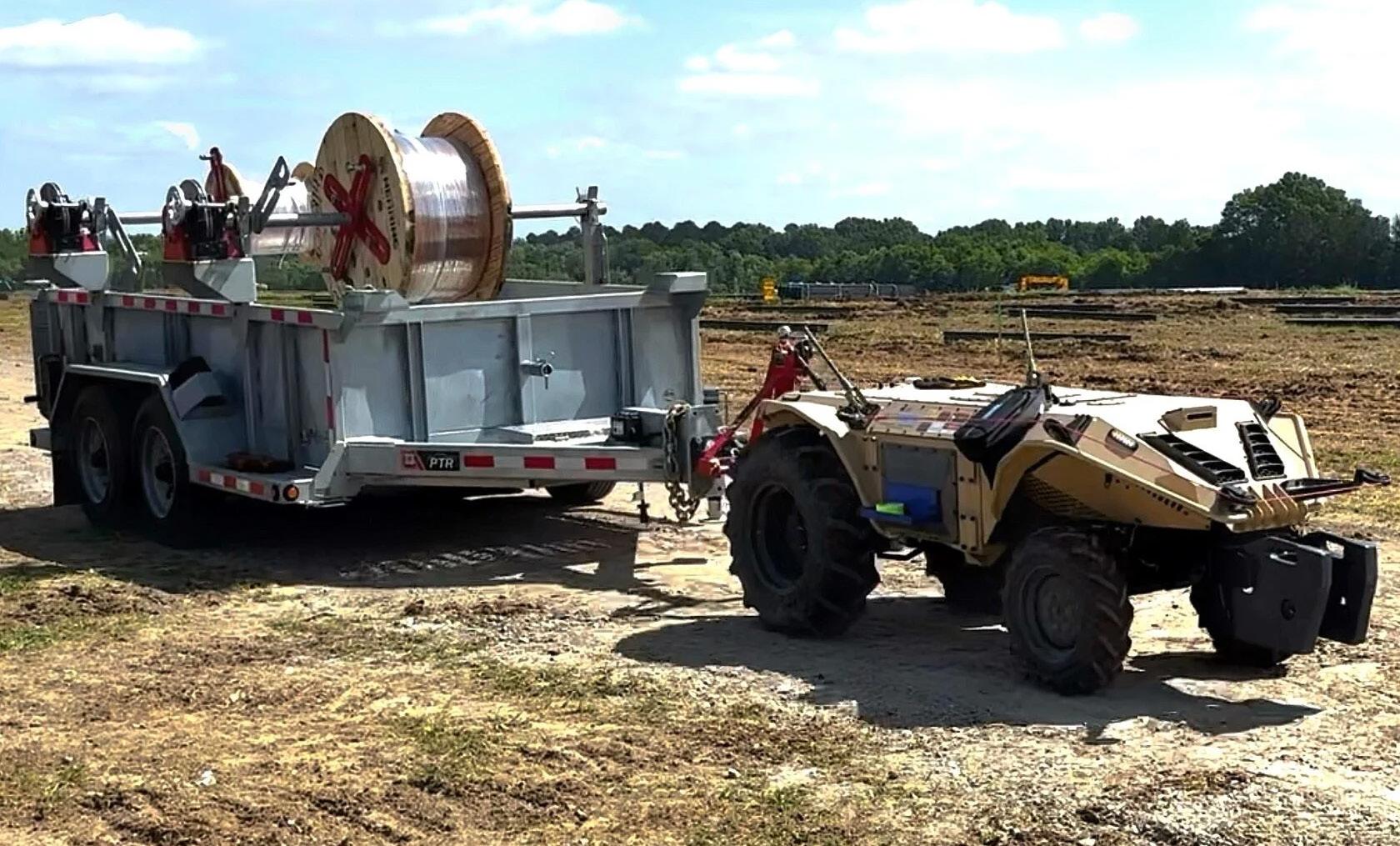
Visually, it looks like an oversized, armored ATV with dirt-drag-racingsized rear tires and neither a seat nor a steering method. It's diesel-powered, so it'll run continuously on the job site without being pulled away for a charge. The Gravion has only 26 hp, which is perfectly suitable considering its primary mission, because it’s definitely not doing any dirt drag racing despite its tires. Plus, that small engine and 23-gallon fuel tank are good for up to two days of continuous operation.
It’s a go-anywhere robot with standard 4WD and a locking differential, so there aren't many places it can't go, as long as ground clearance isn't a factor. 3-point hitch capacity is up to 1,800 lb, and it can pull upwards of 2,000 lb, depending on traction
conditions. The standard rear PTO delivers up to 19.5 hp at 540 rpm, while the mid-mounted PTO operates at 2,500 rpm and delivers slightly less horsepower.
It's available with a dizzying array of attachments: snow blower, forklift, loader, stump grinder, mowers, diggers, backhoe, and many more. It's able to use both the mechanical PTO and a hydraulic pump, of course, which adds to the versatility, just as you see with modern farm tractors.
The entire machine, including any hydraulic functions, is controlled primarily through remote control. It's essentially a giant Swiss Army knife of an RC car. It operates with up to 18 cameras, providing 360° vision to spot obstacles when the operator cannot. However, it can also be programmed to operate autonomously when equipped with its optional LiDAR system. Don’t
worry, it has a “bumper wire” that shuts the machine down if it runs into something … or someone.
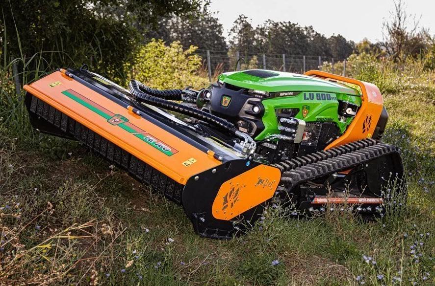
Green Climber specializes in remotecontrolled slope mowers but also offers attachments and accessories, including swinging hammers, stump grinders, boom arms, buckets, trenchers, and snow blowers. Slope mowing, its primary directive, is a challenge for manned vehicles because of their top-heavy nature, which makes steep grades uncomfortable for the operator or impossible altogether without rolling the machine. The Green Climber can operate at up to 60° with its hydraulic track extension, adding up to 20 in. more width on some models.
Power comes from gas or diesel engines ranging from 25 to 100 hp, offering more than enough power for their hydraulic systems to make quick work of grass, shrubs, and thick
The all-new Green Climber TE 160 series features a wider cutting head to tackle grass, weeds, and brushwood with ease. MDB
branches alike. The most powerful of which is the LV1000, which has a lifting capacity of up to 2,866 lb with the appropriate attachment. All functions are hydraulic, as their engines power the hydraulic pump, which in turn distributes its energy to the rest of the actuators, including the drive motors. Their large models come standard with a recovery winch, making them the perfect first responder when your rig gets stuck while hauling one.
All machines are available with Autec or IMET radio remote control systems, typically in the form of a belly box (larger models include a digital display). With up to 500 ft of range, one could clear an entire hillside from the comfort of their Muskoka chair (not included). Typical operation is with a single joystick on the remote, rather than dual levers like old skid steers, which allows simultaneous operation of hydraulic functions with the opposing hand. Despite the reliability of today's electronics, Green Climbers are offered with manual levers in case a problem occurs with the remote or receiver.
Although the Green Climber machines are not currently offered in autonomous versions, their range has
expanded to include remote-control buckets and forklifts, which are a natural evolution for hazardous worksites. With a lifting capacity up to 4,000 lb, these units are the perfect companion for remote worksites on difficult terrain. Their Pocket Lift Plus folds down to only 31 in. for easy transportation and storage, which I imagine will soon start replacing the bulky forklifts you see hanging off the back of flatbed delivery trucks.
I wasn't surprised by the level of electrification I saw at the 2026 CONEXPO, but I certainly didn't predict the proliferation of hydraulic-powered robots. Such solutions provide all the benefits of electronic and hydraulic technology in one powerful package, so shame on me for not seeing it coming sooner. My bold prediction for the 2029 CONEXPO will be widespread adoption of automated mobile hydraulics. DW Gravion is a purpose-built, ultra-low-profile
The Gold Standard in Live Swivels.
utility robot. BotCrew
Stretchable sensor improves AI-driven prosthetic control
Skin-interfaced wearable health technology has a hidden flaw: Many systems work best on smoother skin, which tends to be on younger bodies — not the older adults who often need them most. This is because agingrelated changes in skin, including wrinkles, thinning and dryness, can significantly impact the contact and data quality of wearable devices.
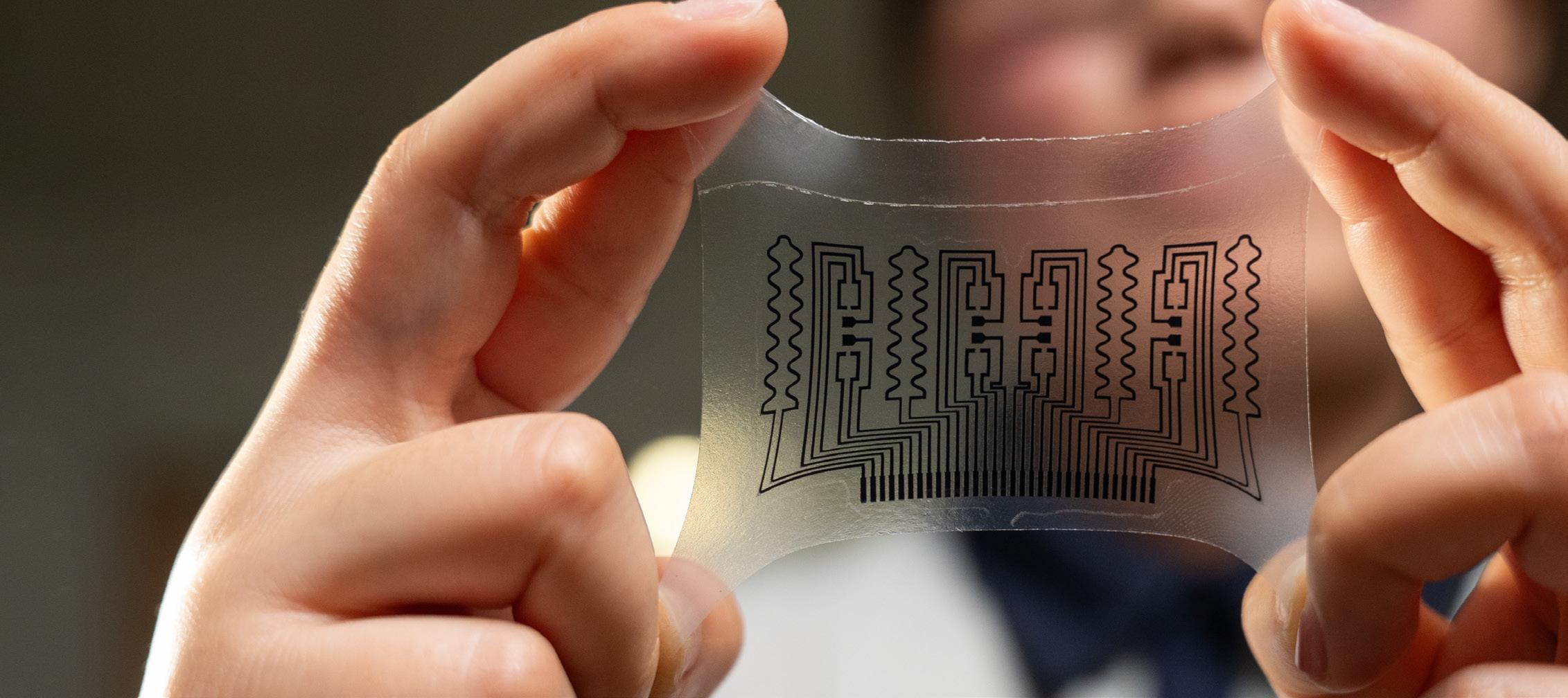
Engineers at Michigan State University have developed a soft, flexible wearable sensor platform called AdapSkin that dramatically improves the capture of the body’s electrical signals, helping artificial intelligence (AI) systems interpret movement more accurately and control prosthetic devices. In testing, the technology improved gesture recognition accuracy in older adults from roughly 60% to more than 97%.
Over the past several years, Jinxing Li, Red Cedar Distinguished Assistant Professor in the College of Engineering and MSU’s Institute for Quantitative Health Science and Engineering, has been developing wearable systems designed to better interface with the human body across a wide range of skin conditions and ages. The breakthrough was not a new AI system but an improvement in the quality of biological data going into it.
Most existing wearable sensors rely on rigid electrodes that struggle
AdapSkin is a flexible and wearable sensor. Garret Morgan/ Michigan State University
to maintain stable contact with aging skin, which tends to become thinner, drier, and less elastic over time. That poor connection weakens electrical signals, introduces noise, and reduces the accuracy of systems designed to interpret muscle activity. AdapSkin solves that problem by using soft, stretchable electronics that conform closely to the skin and maintain stable contact and skin comfort during movement. The system also reduces “motion artifacts” — signal disruptions caused when conventional electrodes shift during motion or exercise.
“Aging skin changes signal quality,” Li said. “We’ve shown that soft electronics like AdapSkin perform significantly better on older adults’ skin
than current commercial electrodes.”
Unlike conventional wearable systems that record signals from only a few points on the skin, AdapSkin uses dense arrays of electrodes to create a more detailed map of muscle activity. Those high-resolution recordings allow researchers to more precisely distinguish between subtle movements, including individual finger motions.
The technology records surface electromyography (sEMG) signals, which are electrical signals generated when muscles contract and relax. Because those signals reflect instructions from the brain to the muscles, they can serve as a noninvasive bridge between the human body and machines.
“With better data, we can better understand the brain’s intended motion,” Li said. “That directly improves the precision and personalization of wearable technology.”
Using the same AI systems and hardware, the higher-quality signals generated by AdapSkin enabled dramatically more accurate real-time gesture recognition and robotic control. That capability is especially important for prosthetics and rehabilitation. Even after limb loss, the brain continues sending signals to the remaining muscles in the forearm. AdapSkin is sensitive enough to detect those faint electrical patterns, allowing users to control prosthetic devices more naturally by intending a movement.
Design For Industry
The technology could also improve stroke rehabilitation and neuromuscular recovery by providing clinicians with clearer, more reliable information about how muscles function over time. The sensors remained stable during longterm wear and movement, an important step for real-world rehabilitation and monitoring applications. More broadly, the findings highlight a growing challenge in wearable technology and AI: Systems are only as good as the data they receive. Researchers say many wearable technologies are
unintentionally optimized for younger users, even though older adults may rely on them the most.
As populations age, Li said designing technology that works reliably across different bodies and skin conditions will become increasingly important for healthcare, rehabilitation, and future human-machine interfaces. DW
Michigan State University, College of Engineering engineering.msu.edu
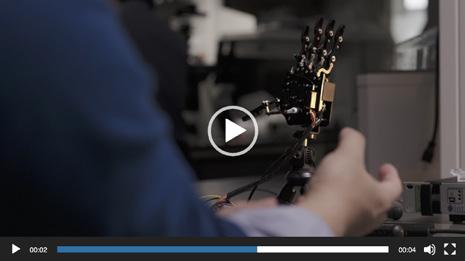
In this video, a user wearing AdapSkin controls a robotic arm by making a fist. Video: Jacon Templin-Fulton
AdapSkin is made to stick to the skin for multiple days for long-term monitoring.
Garret Morgan/Michigan State University
New XY motion stage built for semiconductor automation
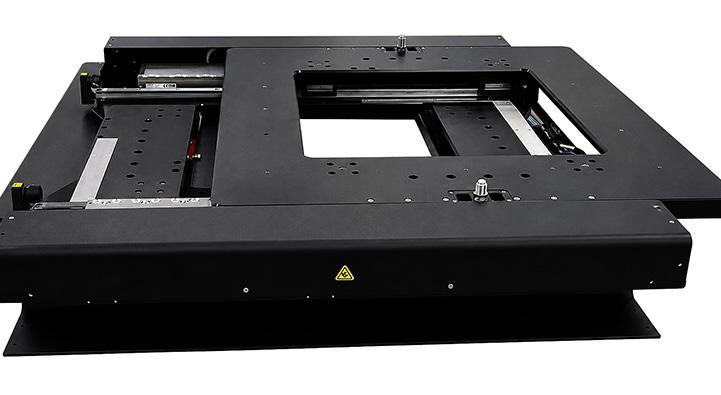
For high-precision applications that do not require the ultimate geometric performance of air bearings, PI's new V-700 series of mechanical-bearing XY stages provides an alternative. The V-783 high-precision linear motion stage is designed and manufactured in the U.S. and optimized for semiconductor inspection, photonics alignment, metrology, imaging, laser microprocessing, biotechnology, microscopy, precision assembly, and advanced automation systems. Specifications include:
• ±0.07 µm bidirectional repeatability and ±0.17 µm positioning accuracy
• 1 nm encoder resolution with incremental or absolute encoder options
• Velocity to 1 m/s and acceleration to 10 m/s²
• Straightness and flatness to 0.75 µm
• 310 × 310 mm (12.2 × 12.2 in.) travel, suitable for 300 mm wafer applications
• 360 × 360 mm open aperture for transmitted-light and inspection systems
• Monolithic XY design with load capacity up to 50 kg
Additionally, an optional absolute encoder provides immediate position feedback after power-up, eliminating homing routines and reducing machine downtime.
When combined with PI's A-800 ACS-based motion controllers, the V-783
XY stage becomes part of a motion platform supporting synchronized multiaxis operation, EtherCAT networking, advanced servo algorithms, and automation-ready system integration. The motion controller is supported by a comprehensive software suite for users and programmers. DW
EDITED BY MIKE SANTORA
Metal coating touchup tips for smarter plant maintenance
Facility maintenance crews face an ongoing battle to protect metal surfaces from corrosion. Strategies include painting stairs, railings, tanks, and pillars more or less frequently depending on the severity of the environment and the quality of the coating job. As Cortec’s Coatings Chemist, Jake Hemberger, explained, “The more time invested in surface preparation and a wellcontrolled application, the longer the
coating will last and the less likely they will need to revisit the job in the future.”
Hemberger recently shared some tips to help maintenance crews achieve that goal on painted metal surfaces.
Common signs of coating failure in industrial environments
The first key is knowing when a coating needs to be replaced. Hemberger recommended annual inspection,
Hemberger recommended annual inspection, adjusted as needed based on aspects like coating type or traffic levels. “Signs of rust or blistering are the most straightforward indicators,” Hemberger explained.
adjusted as needed based on aspects like coating type or traffic levels.
“Signs of rust or blistering are the most straightforward indicators,” Hemberger explained.
However, he suggested that maintenance teams can stay ahead of the problem by placing a sample coated metal panel in the same environment for easier inspection. Fading is another sign that the paint is aging and may need
replacement soon. “It’s not a full alarm, but it is a sign to keep an eye on the coating,” Hemberger said.
Repainting over existing coatings: what maintenance teams need to know
When it is time to repaint, surface prep is just as important as choosing the right coating — especially if rust has already set in or the paint has failed. Hemberger discouraged painting right over the problem: “If there is a paint failure and one paints directly over it, this may slow the failure, but it will still fail faster than desired.” For localized failure, Hemberger recommended scraping the paint away until uncorroded metal can be found and removing or passivating the corrosion before repainting.
If a coating has not yet failed but shows signs of aging, Hemberger said the best practice is to remove the paint and apply a new system. “However, if that’s not possible, painting over existing paint is still doable, provided the surface is clean, there’s good intercoat adhesion, etc.” He noted that sanding the existing paint is a good way to promote better adhesion
between the old and new coats of paint when removal is not possible.
Achieving longer results on a never-ending job
Painting is an important part of routine upkeep. It is a job that never completely ends but that can have longer-lasting results with the proper coatings selection, surface prep, and application. DW
When it is time to repaint, surface prep is just as important as choosing the right coating — especially if rust has already set in or the paint has failed.
If
Tariff-free Interpower Accessory Power Strips (APS) are perfect for multiple IEC 60320 Jumper Cords for smooth integration. Country-specific cords can be terminated with an IEC 60320 connector such as a C13 or C19 to mate with a C14 or C20 outlet in the APS. Now you can plug IEC 60320 jumper cord sets into the APS to power multiple devices— the jumper cord set contains an IEC 60320 plug connector on one end and an IEC 60320 connector on the other end. Made in America.
Cortec cortecvci.com
a coating has not yet failed but shows signs of aging, Hemberger said the best practice is to remove the paint and apply a new system.
EDITED BY LISA EITEL
Royal Opera House gets a new cablemanagement system
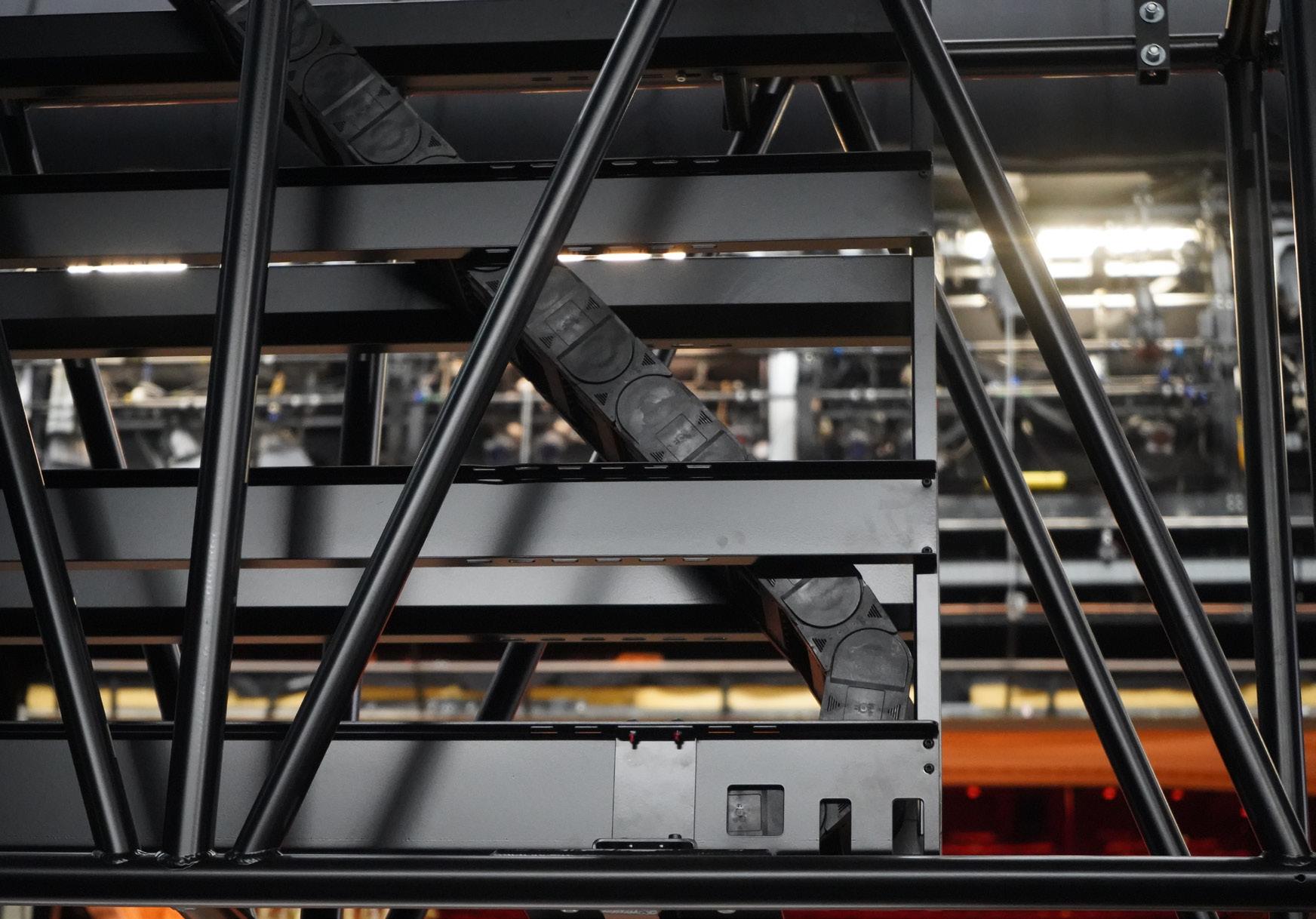
A recent upgrade to the Royal Opera House included customized plastic cable management to support modern LED lighting.
Live theater performances depend on engineering, including those at London’s Royal Ballet and Opera. For example, behind each performance is a technical ecosystem designed to move heavy overhead lighting trusses safely and silently. Following 25 years of reliable service since its original implementation, however, the theater underwent a critical upgrade, needing a new energy supply system that could handle the heavier weight of modern LED technology.
Before its modernization, the Royal Ballet and Opera (ROH) overstage machinery consisted of five vertically moving rows of beams equipped with halogen spotlights. In 2000, motionplastics manufacturer igus supplied the zigzag energy chain system that safely guided the many cables during the vertical movement. For 25 years, this system operated reliably and trouble-free.
But in 2025, the ROH swapped halogen spotlights for LEDs. Although this modern solution significantly reduced energy consumption, it exceeded the load-bearing capacity of the existing suspension points. That necessitated a new support structure
and energy-supply solution to manage the high volume of cables.
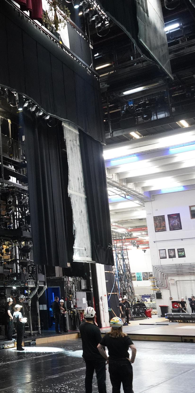
The new lighting hoists now consist of five 21-meter-long rows of aluminum trusses that can be moved at 250-millimeter speeds to heights more than 25 meters. Each row consists of three closely spaced units that can be individually moved. Each unit features a two-truss design with a lower section for the lighting fixtures and a main load-bearing section.
The new energy supply system had to integrate directly into this main structural truss for space savings and stability. It also had to reliably operate under load — supporting the ROH’s
hundreds of annual performances and rehearsals while remaining quiet and visually unobtrusive.
The igus team was again tasked to supply an appropriate cable system. The engineers initially considered alternative solutions such as a motorized cable reel. However, due to the high volume of cabling (including motor, bus, data, fiberoptic and control lines) the zigzag system again emerged as the top option.
Zigzag systems work by folding the energy chain neatly into a basket. As the platform rises, the chain unfolds smoothly and quietly, delivering a space-saving solution for dynamic platforms without placing tensile strain
In 2025, the ROH shifted from using halogen spotlights to LED units, needing a new energy supply solution to manage the high volume of cables. Copious engineering went into the customized zigzag cablemanagement system to support that upgrade. Key was preventing swaying cables and reducing weight to stay within the historic building’s structural limits.
The igus energy chains include robust chainflex motor, bus, data, fiber optic and control cables that reliably withstand continuous movement over many years.
on the cables. These systems also make adding or replacing individual cables a fast and easy process.
Zigzag systems, which fold and unfold vertically, naturally generate a slight pendulum effect due to their geometry. At the ROH, the massive cable load amplified this effect, with initial tests revealing 1-meter lateral deflections during operation. In a stage environment where trusses are close to each other, such wide sway is a safety hazard. So, to counteract this effect, engineers arranged the zigzag in an opposed pattern. By installing two e-chain energy chains per unit that move in opposition, the lateral
forces cancel each other out. Using high-precision laser measurements, engineers confirmed this configuration reduced lateral sway from 1 meter to just 20 millimeters.
For the center truss units, the engineers also implemented two guide boxes with one chain each. On the shorter side units, where space was tighter, they designed two chains to fold compactly into a single box.
The original design for the guide boxes consisted of 2.5-mm-thick steel baskets, for a system weight of roughly 200 kilograms per unit, exceeding the load capacity of the hoisting machinery. Engineers had to reduce
The recent UFO file releases makes one wonder about extraterrestrials (ETs). And what would they learn about Interpower’s Accessory Power Strips and IEC 60320 Jumper Cords? Maybe that humans can use just one country-specific cord set to power up to 12 high-tech devices using universal accessory power. And, if ETs live and fly gravity-free, why are they gravitating to a planet dependent on AC power? Maybe it’s Interpower’s 1-week U.S. lead times or same-day shipping on in-stock cords and components. Special shipping and barcoding available.
the guide box weight to less than 150 kilograms to avoid compromising structural integrity.
The team addressed this challenge by:
• Replacing the 2.5-millimeter steel baskets with aluminum counterparts.
• Performing a structural and stress analysis to identify areas of low stress where that could be safely removed.
• This approach successfully brought the individual system weight down to 112 kilograms, excluding the cables.
In addition to the zigzag system, the igus cable management solution included its E4.56 series e-chain, specifically designed for high loads and long travel, all while maintaining a low-noise profile. Inside these chains, igus installed a suite of chainflex cables, which unlike standard cables, are engineered for continuous motion. These cables also feature electromagnetic compatibility to prevent interference with other stage equipment, as well as an ability to withstand vertical travel and the folding stresses of the zigzag system over millions of cycles.
To meet the ROH’s tight four-week maintenance window, igus delivered 15 complete zigzag systems, including boxes, chains and cables, as ready-toinstall units.
The ROH project has resulted in stage infrastructure that is quieter, lighter, and more durable than what came before it, and it’s expected to outlast the 25-year record of its predecessor. Today, the lighting trusses and its cabling system (though invisible to audience members) is key to the success of every performance. DW igus igus.com
Located on Bow Street in London, the Royal Opera House is home to both The Royal Opera and The Royal Ballet, supported by a workforce of more than 3,000 people. The venue delivers more than 250 performances annually, and its main auditorium seats 2,256 people — yet this represents just a ninth of the entire site’s footprint. Following a major rebuild between 1997 and 1999, the ROH incorporated cuttingedge stage technology, including a 37-meter fly tower capable of holding two full sets simultaneously, and a purpose-built elevator large enough to transport full-scale scenery directly from loading level to stage.
System targets cage creep in linear bearings
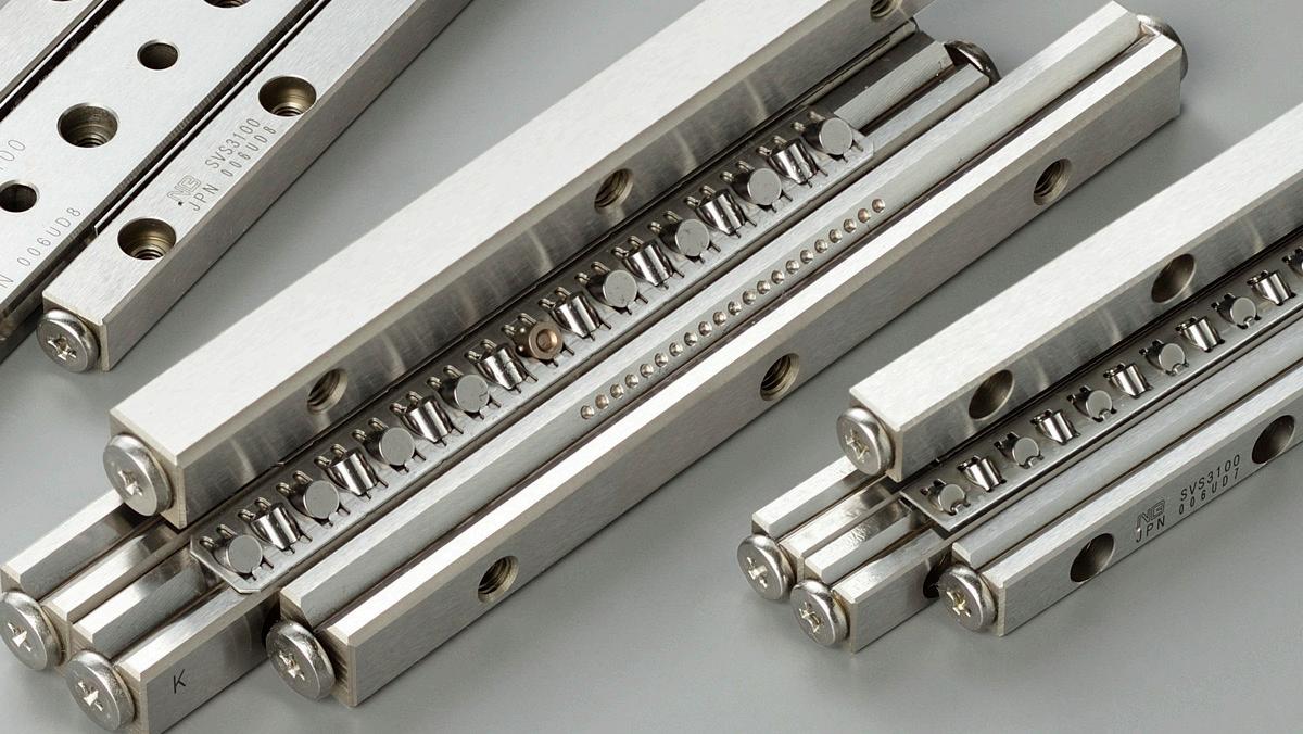
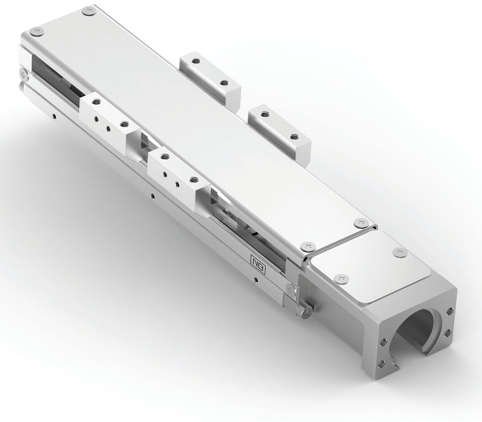
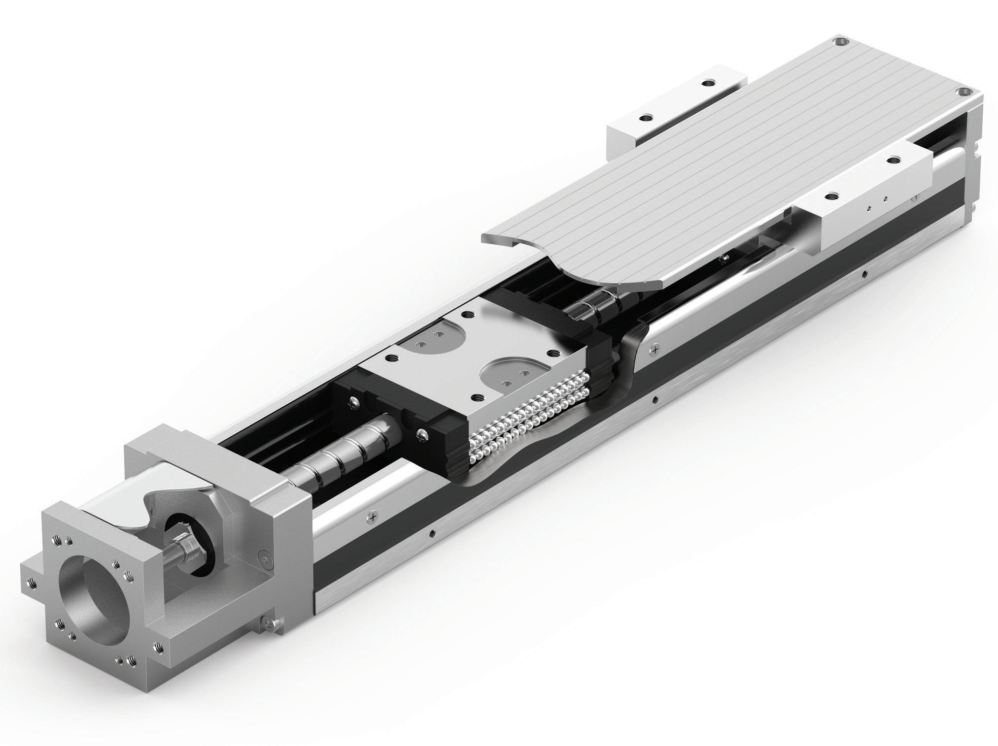
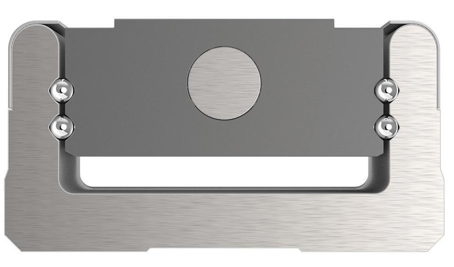
Crossed-roller linear guides integrate rollers alternating between two 90° offset orientations, so these linearmotion supports can carry loads upward, downward, and from both sides.
Certain crossed-roller linear guides from NB Corp. of America also feature cages around the rollers with elements to prevent cage creep.
With conventional linear-guide products, a roller-slip phenomenon caused by repetitive motion of the track base can create deviant in the retainer. That is an issue that can become especially problematic on high-speed axes as well as vertical axes.
NB’s STUDROLLER system is an anticage-creep mechanism to help maintain consistent retainer performance in cross-roller bearings — no matter the axis orientation or speed. Compared with conventional sliding bearings, it can increase the number of effective rollers
by up to 53% … raising load ratings by up to 2.3 times, and increasing contact length between the roller and transfer surfaces by up to 58%.
The system also can run quieter and smoother than ball-circulation guide systems, supporting accurate linear motion, better minute-movement control, less difference between static and dynamic friction, and more stable performance at high and low speeds.
NB Corp. of America has sales branch offices on the East and West coasts and continues to expand its sales network. Its NB Linear Systems use ball or roller elements to reduce friction compared with sliding bearings and support smooth, precise positioning. The design uses large rolling elements and long raceways to increase load capacity and extend travel life — supported by Nippon Bearing’s global manufacturing presence.
MORE FROM NB CORP.
For more information, visit nbcorporation.com. Also check out the most recent Design World coverage of NB Corp. offerings:
SCAN THE QR CODE TO WATCH THE VIDEO
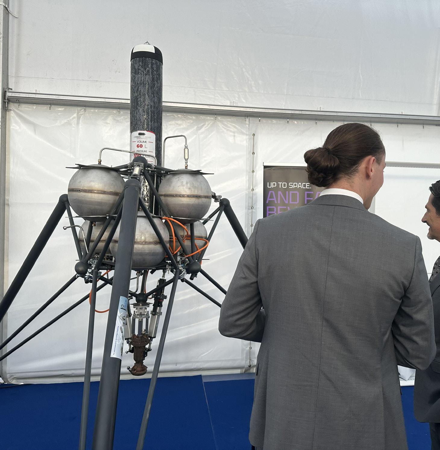
Linear components help Elara Aerospace rocket launch
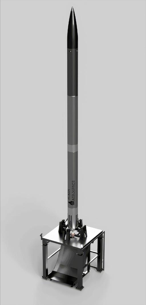
Regal Rexnord brand Thomson recently supplied Elara Aerospace with precision linear-motion technology for its liquid-fueled Methalox rocket.
Elara Aerospace is an academically led initiative founded at the Technical University of Munich in Germany. Its team is working to become the first student group worldwide to develop a liquid-propelled rocket exceeding 100 km in altitude while being fully reusable with up to 100 kg of scientific experiments.
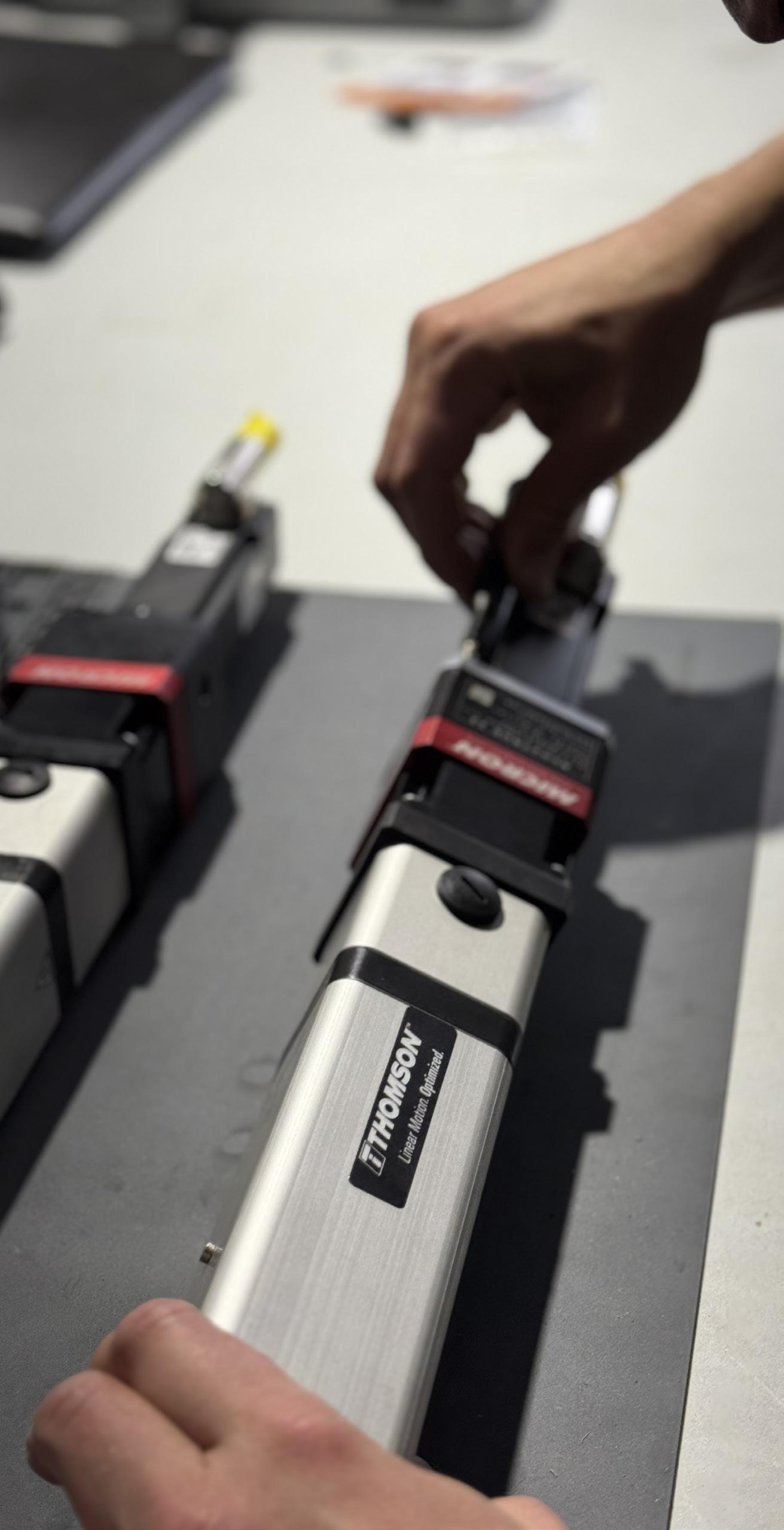
As part of a joint partnership with sister brands Boston Gear and Kollmorgen, Thomson is providing two Thomson PC Series precision linear actuators integrated with Kollmorgen AKM13D servomotors and dual-axis drive systems — along with Boston Gear Micron NemaTRUE planetary gearheads. Together, the components form a coordinated motion solution tailored to the application’s performance requirements.
More specifically, in the Elara rocket, the actuators allow engine gimbaling for controlled movement within a narrow ±5° operating range. The PC Series actuators were selected for their compact design, ballscrew-based construction, and accurate and repeatable motion in space-constrained applications.
“Every commanded movement [in rocketcontrol applications] must be predictable, measurable and easy to verify,” said
In the Elara rocket, linear actuators allow controlled engine gimbaling.
Regal Rexnord’s Linear Motion Division business development manager Anders Karlsson. “For us, the value of this partnership is supplying components and helping Elara build confidence in the actuation approach before the system moves into flight use. Working closely with the team helped us ensure the motion package fits cleanly within the overall engine control architecture.”
The actuators were supplied as individual components so the Elara Aerospace team had flexibility in system design and testing. The motion system is currently being validated on development platforms for use in the rocket’s engine control system.
“For an academically led team working on active engine control, it was important for us to use components that were technically capable and practical,” said Elara Aerospace founder and CEO Tom Luca Reinhardt. “Thomson’s guidance gave us a clear path for the thrust vector control design without adding unnecessary complexity.” DW
Thomson thomsonlinear.com
• Easy and space-saving installation.
• Slim profile, only 12 mm thick.
• Fully encapsulated electronics.
• For Ø24 mm shaft (others on request).
SCAN FOR TECHNICAL SPECS
Linear-motion company Thomson supplied the actuator (complemented by other motion components from other Regal Rexnord companies) for this rocket.
Intelligent Production
BY CONNOR DOHERTY • DIRECTOR OF INDUSTRIAL AUTOMATION • DIGIKEY
Making factory floors smarter
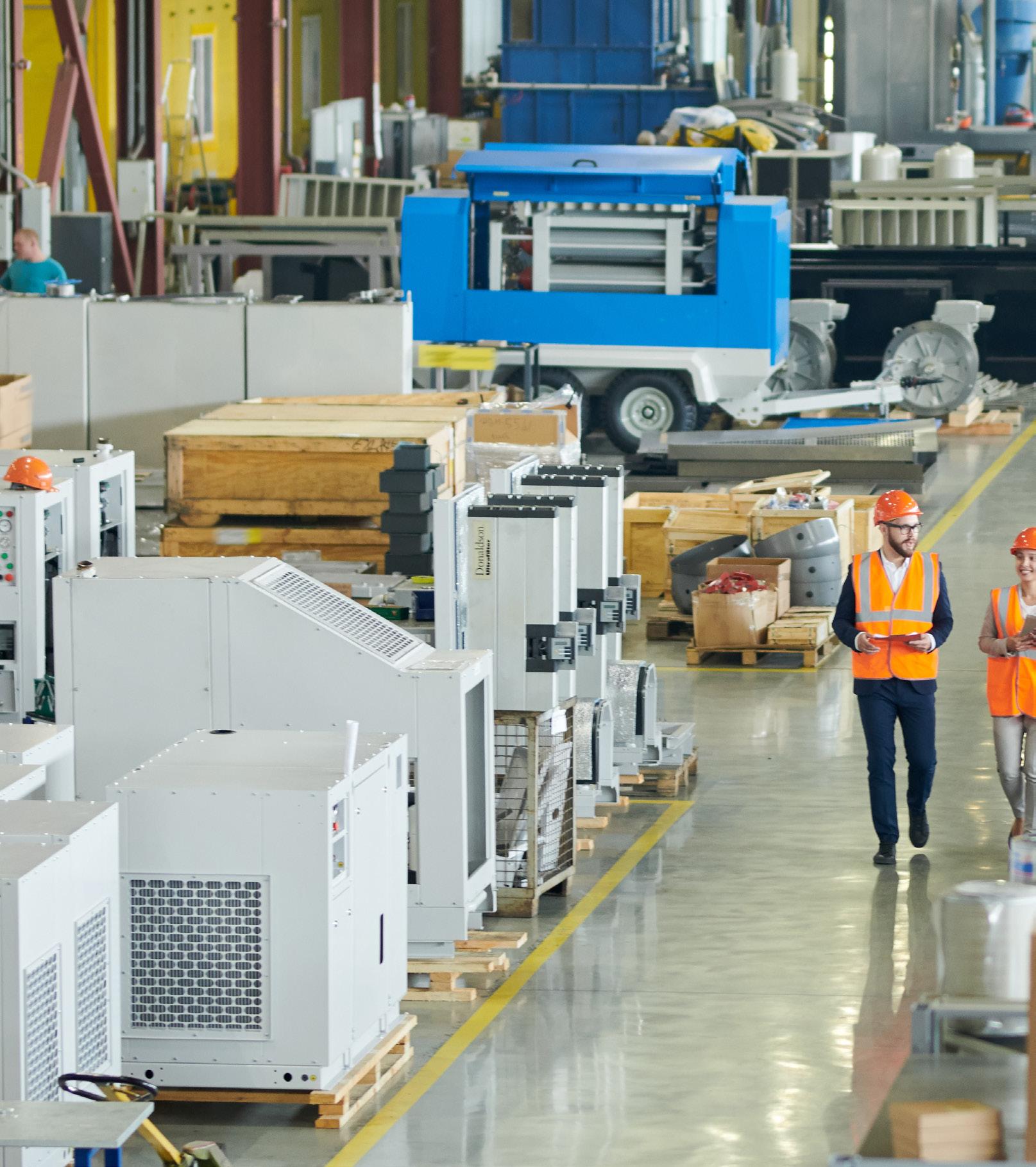
Today’s manufacturers must fully automate complex systems, speed operations, and use fewer resources than in the past. The central challenge is effectively leveraging industrial innovations while managing change on the factory floor.
Manufacturers in North America today must navigate geopolitical uncertainty, aging infrastructure, and shifting compliance requirements.
Consider some specifics. First of all, it can be difficult to integrate new systems into existing equipment: Many production facilities (across markets and regions) have older and often outdated systems not designed to support modern data and AIdriven technologies. The newer the technology, the harder it is to connect to such equipment. In addition, factoryfloor data quality can be lacking … and AI’s benefits are only as good as the data it’s fed. Manufacturing operations need enough historical data to establish a baseline before a system can reliably flag if something is different or off … otherwise, there’s no way to get ahead of problems. In many instances, building that foundation takes time and resources that are unavailable.
Of course, more connected devices also increases cybersecurity risks — and this potential liability requires ongoing attention as systems are increasingly integrated.
Despite challenges, the opportunity for smarter, more efficient factories is real. AI predicts equipment failures in advance, digital twins let manufacturers test ideas without disruption, and edge computing delivers realtime intelligence. The main challenge is integrating these tools to unlock their full value.
Geopolitical uncertainty in the form of changing tariffs, trade policies, and product availability can complicate component purchases as well. Machine builders need complete information about a component’s country of origin to make informed decisions and understand alternative options.
On top of all this, the technology landscape for automation is increasingly complex.
Yet, their capabilities offer all-new ways to improve manufacturing output and efficiency.
More complexity … and opportunities
Globally, manufacturers are adopting new technologies such as AI, sensors, connected devices, and edge computing to program machines, predict issues in advance, and reduce the personnel and resources needed to keep operations running smoothly. The result of these new technologies is a factory with better visibility. Decisions can be made in realtime, systems are more efficient and small issues don’t become big problems that could shut down machines.
DigiKey digikey.com
Modern sensors are helping enable all of this. They can continuously monitor equipment and detect early warning signs of wear to ultimately prevent breakdowns and downtime.
Digital twins and edge AI in manufacturing
Modeling and simulations with digitaltwin technology is increasingly common. With it, manufacturers create models of whole systems in a simulated environment. Then they can evaluate how changing one factor affects real-
world production and efficiency. AI continually makes the information used by these digital twins more accurate. Edge AI — running on field devices instead of an offsite data center — is seeing rapid adoption as it’s faster than cloud-based approaches needing internet connectivity and affected by network latencies. For example, a device on the factory floor with edgeAI software might identify defective product and trigger a response faster than a system needing to send data to a central location.
A secure production environment
Many connected machines, sensors, and systems today include builtin security controls that don’t rely on software for cybersecurity. While these controls originate with component suppliers, distributors are working to making this cybersecurityrelated information more easily accessible. That way, engineers can verify compliance when choosing automation components and confirm the capabilities of what they’re specifying or purchasing. DW
Newlab Detroit provides for the future manufacturing
PAUL J. HENEY •
provides a future of manufacturing
VP, EDITORIAL DIRECTOR
This Spring, I had the opportunity to visit Newlab in Detroit, and it gave me real hope for the future of manufacturing in America — as well as how to better harness each other’s strengths and create community within our industry.
Newlab is a global organization that started in Brooklyn, N.Y. It later expanded to Detroit and recently broke ground on a facility in New Orleans. The organization also has beta space in Riyadh, Saudi Arabia and a satellite office in Montevideo, Uruguay.
Here in Detroit, it’s part of the incredible Michigan Central campus, sort of an economic development ecosystem that encompasses 30 acres. Michigan Central includes the iconic Michigan Central Station, an 18-story Beaux-Arts complex built in 1913 that was left to waste for decades before being renovated and re-opened in 2024. Today, it’s being redeveloped as a hotel, public shops, The Mezz (with space for business meetings and retreats, along with workspace), workforce development areas, and more.
Riley Hall is the General Manager & Head of Membership for Newlab, and he described the organization as having three legs: corporate membership (startups), commercialization, and venture investment. He heads up the membership department for startups.
“I’m really focused on providing the services at a reasonable cost to the startups,” he said. “Newlab knows that we can’t grow off the backs of the startups — and trying to build a business strictly on membership fees is not anything that we’re interested in. With the other two legs, commercialization and venture investment, that’s where
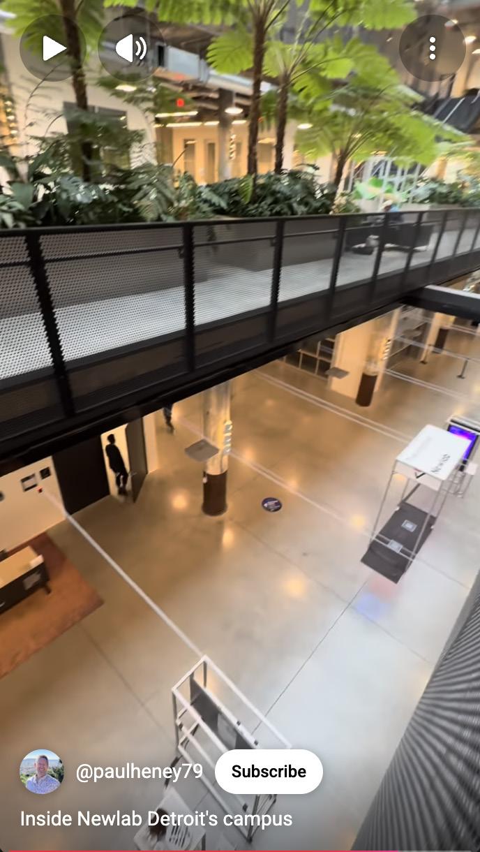
Newlab Detroit is a part of the 30-acre Michigan Central campus, an economic development ecosystem, and is housed in the beautifully restored historic Book Depository, now a 270,000-square-foot innovation and startup hub. Paul J. Heney
we have the ability for outsized returns. I have a colleague who works specifically with large corporate and government partners to define scopes and projects and pilots around a specific use case for that company — and then we attach the startup technology into the back end. Those are funded pilots that we design, run, and manage and then deliver results against, and then venture investment on the back end. Since we’ve opened in Detroit in 2023, we’ve made about 14 investments into member companies.”
Hall also noted that Newlab as a global organization has made about 70 such investments since it started in 2016.
Think of Newlab as a big manufacturing and innovation playground, where startups have space to develop their product, using expensive shared equipment such as 3D printers and oscilloscopes, which are generally cost prohibitive for the individual companies to own themselves. Startups also have access to world-class prototyping and fabrication facilities so they can test, iterate, and scale. Newlab’s Detroit outpost includes a Casting Room, CNC Room, Electronics Lab, textiles lab, robotics lab, and a wood shop.
While visiting, I encountered some innovative startups, such as MotMot, which has developed what its owners
“I’m really focused on providing the services at a reasonable cost to the startups... Since we’ve opened in Detroit in 2023, we’ve made about 14 investments into member companies.”
— RILEY HALL • NEWLAB
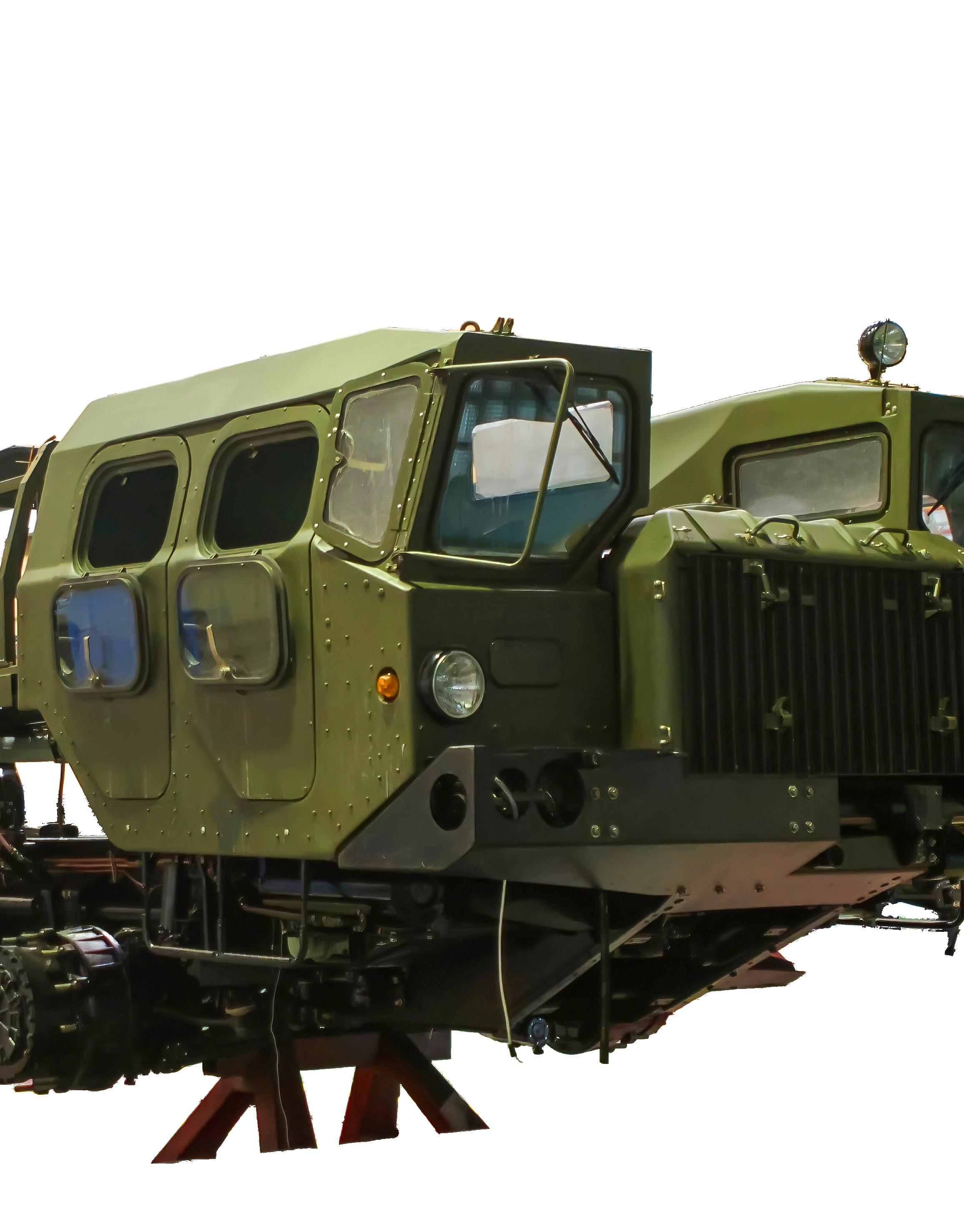
call the Autonomous Underwater Robot, or AUR. The AUR is deployed into water mains, storage tanks, water treatment plants, culverts, and more, allowing for inspection of these submerged environments. I also saw robotics companies like Intermode (which makes a truly autonomous ground vehicle for military applications) and Inbolt (which focuses on physical AI for factories).
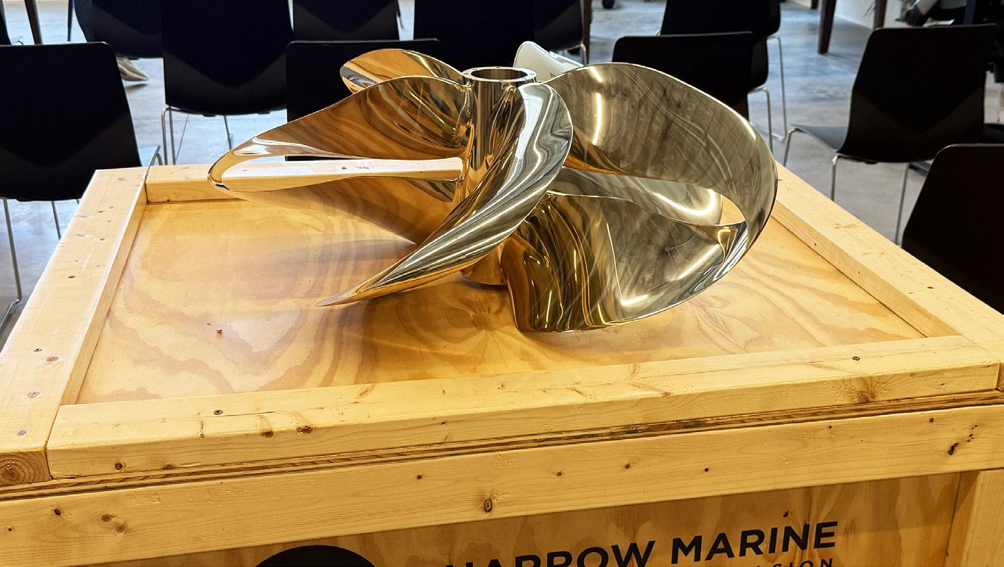
One of the incredible stories we heard was how Sharrow Marine’s whole manufacturing process was turned on its head (in a good way), thanks to Newlab. Greg Sharrow, the company’s CEO & Founder, is an avid boater who was inspired to create a new type of propellor. Boat propellors are a design that hasn’t really been much improved on in the last century or two. But Greg’s innovative design, comprised of what looks like three or four twisting ribbons of steel, reduces noise dramatically,
Manufacturing
is more efficient at many speeds, and creates less vibration. What was really holding this startup back was the wait time for the castings. Sharrow’s lead time for the castings was 130 days. No matter what options they looked into, they could find no way to reduce that significant time lag.
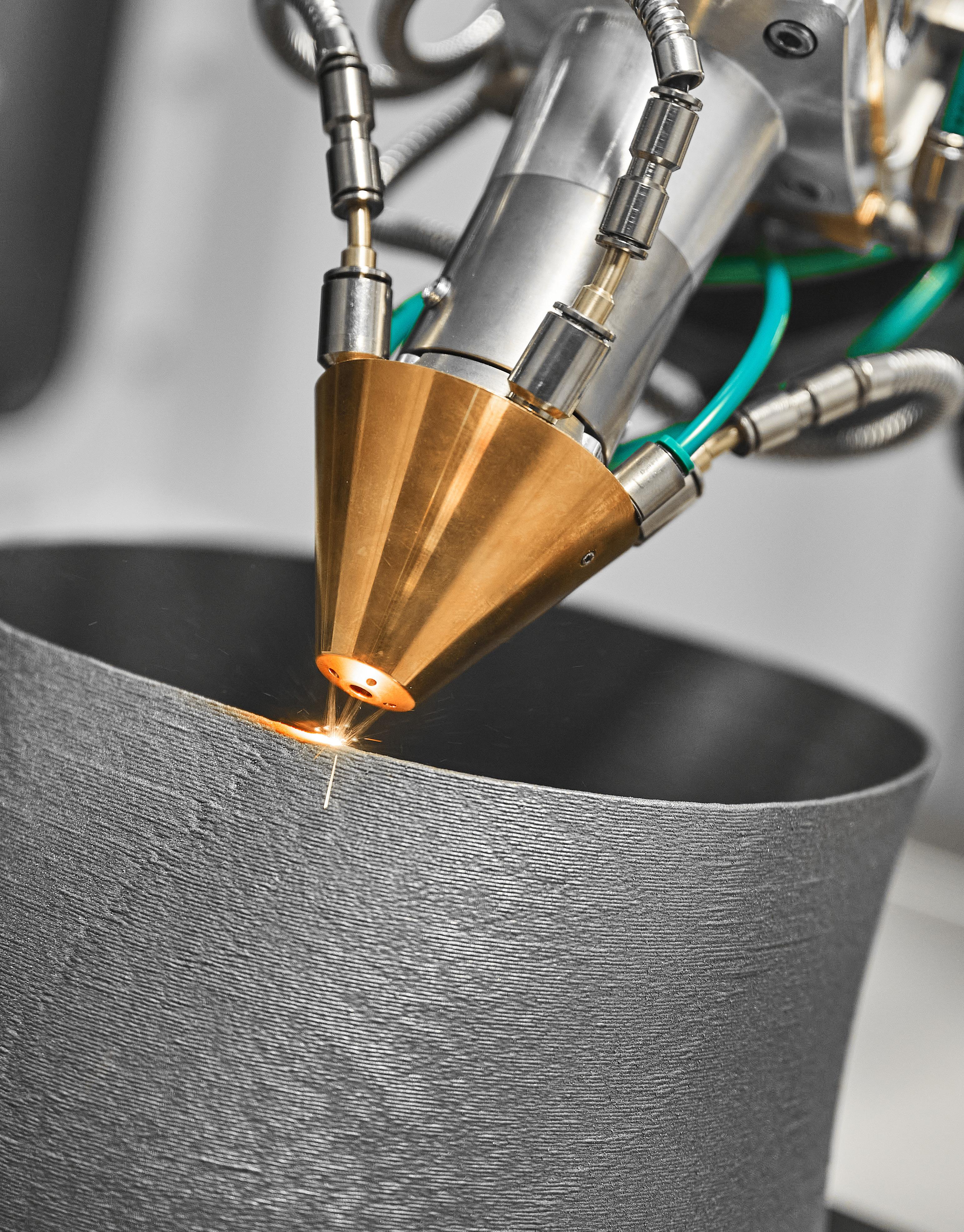
But through Newlab, Greg was introduced to Dan Michalski, part of Ford Motor Company’s Manufacturing group, after a chance conversation in an elevator here about manufacturing hangups. Dan told Greg they had options and were willing to give back and help out local startups. Soon, a meeting was set up on the Ford campus.
“We walked into the boardroom, and there’s a team of engineers sitting in there, along with other engineers Zooming in,” said Sharrow. “And they
the beginning. After nine months of working together, now we’ve proven out the process.”
Now Sharrow Marine’s propellers are being produced in a Ford plant in a mere three days’ time — an incredible reduction from the 130 days that Sharrow Marine was dealing with prior.
all looked at me and said, ‘What can we do to help you?’ We sat down and I explained the overall company and what we do. Within about seven minutes of explaining what our challenges were, someone said, ‘Have you tried sand casting?’ and I said, ‘We’ve been told we just can’t make this shape with it.’ And then the Ford engineer said, ‘We can.’ I thought, you’ve got to be kidding me. It was like walking into a movie, and that was
“Our goal is to replace every propeller on Earth that should be replaced by a Sharrow Propellor with a Sharrow Propellor. We’ve got a lot of work to do,” said Sharrow. “There are 2 million propellers sold to the outdoor boating market each year. And the propeller industry is a $95 million per year industry. Propellors are ubiquitous in modern life and are everywhere around us, in everything from windmills to appliances. Our goal is to develop the technology for all of the other market verticals ... we now have over 200 patents around the world.”
While things like AI and regulations are often touted as ways to bring back manufacturing to the United States and to improve processes, my visit to Newlab Detroit proved that good oldfashioned networking and collaboration is never to be overlooked. DW
Left to right, Mark de la Vergne, Director, Network Growth, Michigan Central; Dan Michalski, Additive Manufacturing Operations Supervisor, Advanced Industrial Technology & Platforms, Ford Motor Company; and Greg Sharrow, CEO & Founder, Sharrow Marine. Paul J. Heney
SCAN THE QR CODE TO WATCH THE VIDEO
Lisa Eitel • Executive editor
DIGITAL INTEGRATION OF MOTION SYSTEMS
In a recent webinar conversation with colleagues, we touched on how manufacturing is undergoing a fundamental transformation with motion systems in these settings so core to integrated digital ecosystems.
Why are motion systems useful for data-driven manufacturing optimization? Well for starters, commanded moves produce measurable values — including position, velocity, acceleration, torque, current draw, vibration, and thermal values. These signals reflect work being done for immediately actionable insight into product output and machine health.
Motion controllers lead hardware technologies
Motion controllers are electronics seeing all the advancement of Moore’s Law — and they continue to evolve from proprietary standalone components to open components with realtime processing. Another benefit is all the realtime communications on EtherCAT,
PROFINET, and time-sensitive networking (TSN) with drives, sensors, and the enterprise systems of digitaltransformation or DX operations.
Electronics are also why smart drives are increasingly important to digitization — especially for embedded safety, diagnostics, and edgecomputing capabilities. Many such drives now essentially work as edge controllers, gateways, and bridges.
Just as important as controls and drives are sensors to track conditions in the real world in realtime. Encoders and other sensors with built-in intelligence first and foremost offer motion feedback that’s more advanced than legacy options … plus they support functions such as health monitoring.
Digital integration in military manufacturing isn’t only for procurement tracing. Connected motion controls ensure assemblies are within specifications.
Adobe Stock
Motion Control
The catch is that sensor signals also need to be output in realtime. Suitable here are serial interfaces such as BiSS C for dynamic axes. BiSS C and competing interfaces are often found on absolute encoders (including Renishaw RESOLUTE, EVOLUTE, and FORTiS encoders, for example) as these allow connections to drives and controls in turn networked with digital architectures.
Application-specific sensors can close the loop on motion controllers’ internal position values and traceable metrology values. So that way, operators get predictivemaintenance recommendations and compliance documentation that are both backed by data.
These days of course, many motion components combine multiple hardware subcomponents so engineers can focus on their integration into digital infrastructures. Some of maxon’s motors for example include drive and control electronics. Then for the motion axes on which they install, EtherCAT connectivity allows synchronization, supervision, and diagnostics via PLC, IPC, SCADA, or edge controls.
Physik Instrumente (PI) nanopositioning mechanics are another example having controllers for easier integration into automation networks. Actuators from motion supplier Harmonic Drive have the strain-wave gearing (for which the supplier is best known) integrated with brushless servomotors, encoders, and servodrives using CANopen or EtherCAT to bridge to digital infrastructure.
After all, when the entire actuator is integrated and tuned, engineers can put more effort to higher-level commissioning.
Software puts motion in digital infrastructures
Software ecosystems are increasingly important for unifying realtime motion control, data acquisition, simulation, and lifecycle engineering workflows. That’s because they let engineers model, monitor, and optimize performance of axes within broader manufacturing and enterprise systems.
Taking motion systems from isolated low-level controls to connected ecosystems are model-based design tools, cloud platforms, IoT frameworks, and things that are more commonplace to the motion industry such as IEC 61131-3 compatibility.
Integrator and provider Hawk Ridge Systems uses SOLIDWORKS and Dassault Systèmes’ 3DEXPERIENCE platform to let engineers build models, simulations, and data management for motion hardware and downstream manufacturing. These define motion-system dynamics, because after all — structural dynamics and servo performance are entwined at high bandwidths.
Cloud-based management of designs and data mean motion systems are in digital-infrastructure documents
Centrifuge Separates Blood... and Motors
A centrifuge separates plasma from blood at donation facilities and requires a motor to operate trouble-free at very high speeds – silently and with no vibration. Not all motors can do that, and that’s what separates the best motors from the rest. Bodine Electric Company makes the best motor for centrifuges. Give us your requirements and we’ll get you the best motor.
that can be audited and used in other ways.
Of course, all-encompassing software tools aren’t the only option. Many motion-hardware suppliers offer more targeted software and then opensource compatibility lets engineers use other tools for the final steps of digital integration. For example, Chieftek (cpc) offers linear-motion hardware completing digitally connected machinery (including linear guideways and linear motor stages) but has in recent years put increased emphasis on its cpcStudio PLC integrated development environment or IDE software. That helps design engineers get deterministic motion from gantries, precision stages, and robotics.
In the same way, software from motion-hardware supplier Physik Instrumente allows simulation and safety setup for multi-DOF kinematics via standard industrial connectivity options.
Industries leading motion integration into digital infrastructures
Packaging along with warehouse automation is integrating motion into ERP and MES digital infrastructures. Perhaps surprisingly, there’s even motion in the hyperscale data centers currently proliferating across the U.S. That includes all the connected heavy equipment used in the construction of these facilities as well as robotics to monitor, maintain, and even guard the servers at these sites once they’re up and running.
Other leading spaces are semiconductor manufacture (for quality assurance), automotive production, medical-device manufacture (especially for product traceability), and aerospace and defense.
Earlier this year at MD&M West, we spoke with Gene Matthews of Regal Rexnord’s Kollmorgen. He shared his insights on designs for satellites, rovers, and other spacecraft needing embedded motors. Essentially,
Matthews argues that work has really segregated into separate aero, space, and defense markets. It used to be that space was a really tiny market, so designs were expensive one-off designs for NASA. Now, the industry is booming with many small space companies putting tons of their own compact rugged designs in space.
Essentially, different motion suppliers have come to specialize in serving very specific space applications … because after all, outer space is totally different than low-Earth orbit with different levels of radiation and temperature extremes and so on.
Of course, due to the remoteness of designs in space (and inability to just “pop over” and check on them) all of these motion systems need to be tied to digital infrastructure.
Even before their launch or use, aerospace and defense tolerances are tight, reliability is paramount, and validation requirements are stringent — so integration is key. That’s true even during the manufacture of parts. One Airbus-led project uses Physik Instrumente’s six-DOF hexapod to make carbon-fiber reinforced polymer or CFRP components. These wing shells need precise contouring, drilling, and sealing — and sufficient precision is only possible with an articulated robot complemented by a hexapod and DX functions including condition monitoring.
The same is true for parts produced by Renishaw’s metal additive manufacturing systems for the production of parts (including those of titanium, Inconel, and other steel alloys) impossible to make with traditional manufacturing. Powder is fused in layers down to 20 μm which requires (among other technologies) servo-driven linearmotor stages, optical encoders, and realtime machine monitoring that would be overkill elsewhere.
Design World’s own Lee Teschler often scoffed at the idea of edge devices and the concept that digital transformations are something new.
He’d quietly say, “They’re just using sensors.” To acknowledge this point and stay with aerospace examples ...
For aerospace manufacturing with advanced machine tools, calibration devices and coordinate measuring machines or CMMs along with software optimize setup precision.
On-machine probes (another solution from Renishaw) allow machine configuration, tool setting, and in-cycle gauging as well as first-off component inspection. Contact and noncontact (laser) tool setting and detection systems define motion and DX-grade functions for CNCs.
Flight simulators (usually six-DOF Stewart platforms) synchronize with realtime aerodynamic models, avionics software, and rendering engines (for what’s displayed to pilots inside the simulator). All this happens with sensor feedback via Ethernet networking, realtime OSs, and hardware in-theloop. So, the actual motion system can deterministically reflect the digital twin and serve as physical equipment and a very fancy output for high-bandwidth simulation.
Satellite test equipment has motion axes with accuracy to within arcseconds (1/3,600 of a degree). Sensor feedback — including every movement, load variation, vibration, thermal vacuum, and shock — goes to controls as well as data acquisition operating alongside the equipment for documentation.
As with a lot of things, Lee Teschler was right: Much of this digital innovation we see originates from extremely advanced measurement — feedback from sensors. DW
Custom Synchronous Drives
You’ve created a unique design. Now relax. We’ll take it from here.
Custom precision manufacturing.
Part 2 of 3:
ELECTRIC ACTUATION to replace hydraulics
ELECTRIC ACTUATION hydraulics
Lisa Eitel • Executive Editor
In the last installment of this series, we outlined how linear components (including guides, cylinders, and electric actuators) perform well for presses. Here, we describe the requirements for using electromechanical actuation on heavy-duty machine tool axes.
Consider how some industrial forming machines use screwtype electric actuators rather than hydraulics to apply controlled force over a set distance. These actuators usually combine a rotary electric motor (such as an ac servomotor) and a ballscrew or planetary roller screw to precisely advance a ram, platen, or slide. Complementing the motion system are thrust bearings for end support and axial load handling, linear guides flanking the screw, and force and position sensors for feedback.
Ballscrews have lower load capacity than fluid-power solutions yet are extremely precise. Planetary roller screws, which use threaded rollers rather than balls for more contact (and therefore transmit more power) can output axial forces approaching those of some hydraulic cylinders … though the peak force density of all but the largest roller screws is still lower than that of hydraulics.
Shown here is a modern automated stamping machine on a refrigerator production line. Electromechanical solutions abound in such equipment — with mechanical servopresses and automated transfer systems common on appliance metalforming. Notice for horizontal indexing this machine includes rack-pinion drives flanked by profile-rail linear guides. Adobe Stock
Schaeffler Ewellix SRSA/SVSA electric cylinders are the fastest and strongest linear actuators in Schaeffler’s portfolio. Planetary roller screws help deliver efficient linear movements with extremely high loads and full controllability at high speed. Housings are made of steel for high stiffness and robustness.
That said, many applications’ requirements are within the ranges of stock electric cylinders based on planetary roller screws. A representative actuator with a 75-mm cylinder screw size might deliver peak forces to 500 kN — previously possible only with hydraulics. What’s more, the precision recirculating roller screws and short screw leads (1 mm) deliver this force with high positioning accuracy for positioning adjustments controllable down to micrometers.
Both screw-based types of actuation offer the efficiency and programmability of motor-based systems as well as relatively easy integration into networks for advanced digital configuration and monitoring. These benefits make electromechanical linear actuation worthwhile in a wide variety of machinetool and other applications … justifying the extra engineering and maintenance required to establish and sustain their reliability and performance in heavyduty applications.
Thermal effects and the importance of lubrication
In heavy-duty machines, a major threat
to ballscrew and planetary roller-screw performance is heat. High RMS torque from frequent speed changes can make the nut and support bearings especially hot even if the axis is operating slowly. In fact, all the contacting elements inside the nut often means it runs hotter than the screw and frame, so there’s uneven expansion and load distribution. Unfortunately, if the screw overheats (through thermal conduction via contact with internal nut elements) it can lengthen and clearances increase … and machine performance falls.
So, specifying screw-based actuation for heavy-duty axes requires careful quantification of how hot the screw will get during normal operation. Then if needed to address axial growth, a rotary bearing at one screw end can be left free or complemented with an expansion compensator or other sensor-based solution.
Absolutely central to keeping operating temperatures in range is the oil or grease within the assembly. This is why regular relubrication is critical — especially for roller screws.
“In high-duty-cycle applications, thermal buildup can lower lubricant
...All In
Less Space
BG Actuator–Greater Loads, Precision & Rigidity
Why our single axis ball screw slide guide bests the competition:
Circuits positioned closer to base for more stability.
Four ball circuits (not just two) for moreload and accuracy
Single, U-shaped rigid steel rail and base can be one-end supported
Balls have 4, not just 2, points-of-contact to guide block and rail for optimum stability
effectiveness, reduce fatigue life, and cause thermal expansion that can degrade backlash and precision,” said engineer John Fenske of Tolomatic. “To mitigate these effects, it’s always wise to have scheduled maintenance with relubrication” — especially when using screw-based actuation in heavy-duty machinery, noted Fenske.
“Other options are hightemperature greases or selecting an actuator that is oil-cooled.”
The maximum allowable nut temperature dictates which materials, coatings, cages, seals, and to some extent preloading are most suitable. In oil-cooled actuators, the screw is usually in a sealed compartment filled with oil that acts as both lubricant and coolant. Viscosity is carefully selected (along with additives) to prevent film breakdown or (the opposite issue) thickness that exhibits churning.
“The stroke length of the actuator should also be considered,” added Fenske. “In applications with short strokes needing a single rotation of the screw or less, lubricant distribution can be affected, causing thermal buildup and premature failure. A well-planned relubrication schedule is critical in these cases,” concluded Fenske.
Of course, machine-tool settings often include shavings, abrasive particulates, and detrimental fluids that (unless the ballscrew or roller screw is fully sealed and ruggedized against ingress) could contaminate the lubricant within.
Shock loading on heavy-duty axes
One key advantage of hydraulic cylinders is how their fluid-based physical linkage to axes’ end effecting protects the rest of a machine assembly against shock loading. Such shock
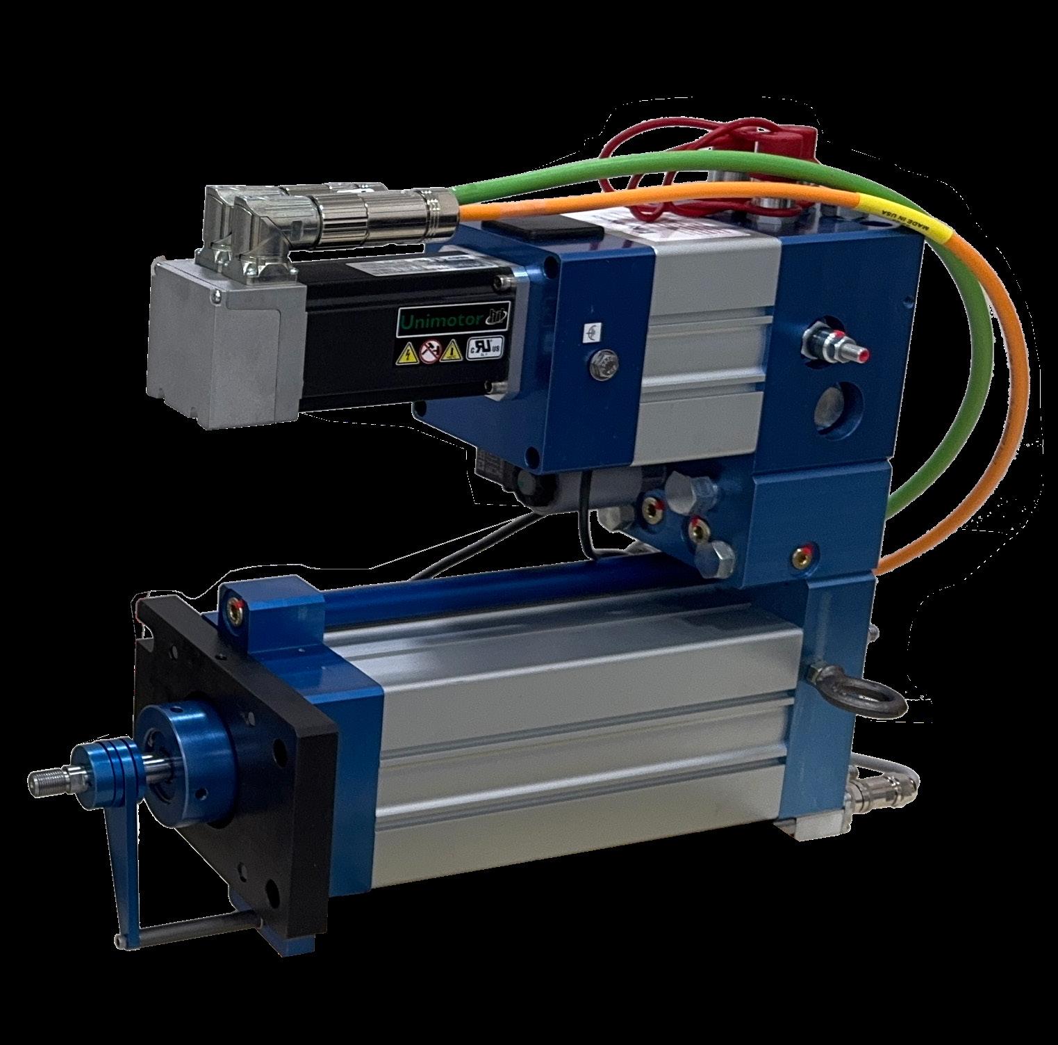
Kyntronics’ Servo Hydraulic Actuators (SHAs) deliver precise servo control through built-in position sensors and pressure transducers. They only draw power when needed (power-on-demand) and support IoT functions such as predictive maintenance and overall equipment effectiveness (OEE) monitoring. The actuator has many configurations and can be installed in any orientation.
is common in machine tools that output high forces that are sudden (or suddenly reversed) or subject to repeated impacts. On screwbased assemblies, such loading can induce plastic deformation (including Brinelling) on the linear drive as well as guide assemblies, even if peak load stays within rated limits.
“Shock loads are a concern due to the heavy tooling and the general inertia that is typical in these systems,” said Fenske. “A roller screw will mitigate shock loads due to its structural stiffness and larger contact area, but if the risk of shock loading is high, designers should consider selecting higher-capacity roller screws and possibly shorter screws to reduce backdriving tendencies during shock events,” he said.
Any applications involving especially challenging loading should be outfitted with mechanical drives that won’t
exhibit torsional screw windup, nutroller skew, or cage instability. Though service life for screw drives depends on duty cycle and the motion profiles of the axis’ functions, machine tools that could damage assemblies with sudden loading should be specified with a generous static safety factor.
The importance of bearings (both radial and linear)
Any screw-based electric actuation of heavy-duty machine-tool axes requires radial bearings (at the motor and screw ends) as well as linear bearings engineered, specified, and installed to prevent misalignment and side loading — especially on axes involved in pressing or stamping. In addition, the machine frames to which bearing and guide elements are assembled must be rigid … or else edge loading and localized Hertz stresses can occur. That’s because ballscrews and roller screws don’t tolerate radial and moment loads or lacking parallelism.
Radial and linear bearings together must also accommodate the excitation of critical speeds as well as torsional and axial resonance modes — and minimize any skidding, fretting, and noise (and worse yet, plastic deformation) that can accompany vibration. Stability in the face of rapid accelerations and reversals for a given characteristic speed DN is especially important on machine-tool axes.
Whether hydraulic cylinder or servomotor-screw driven, the most
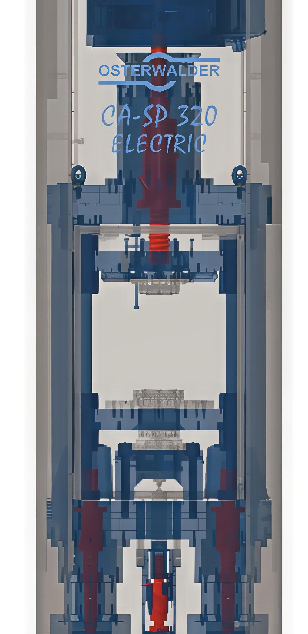
This Osterwalder AG powder press uses several servoelectric actuators based on NSK ballscrews for 2,000 kN press force. Plus, the press uses 80% less energy than comparable presses based on hydraulics … and parts are output with higher dimensional accuracy.
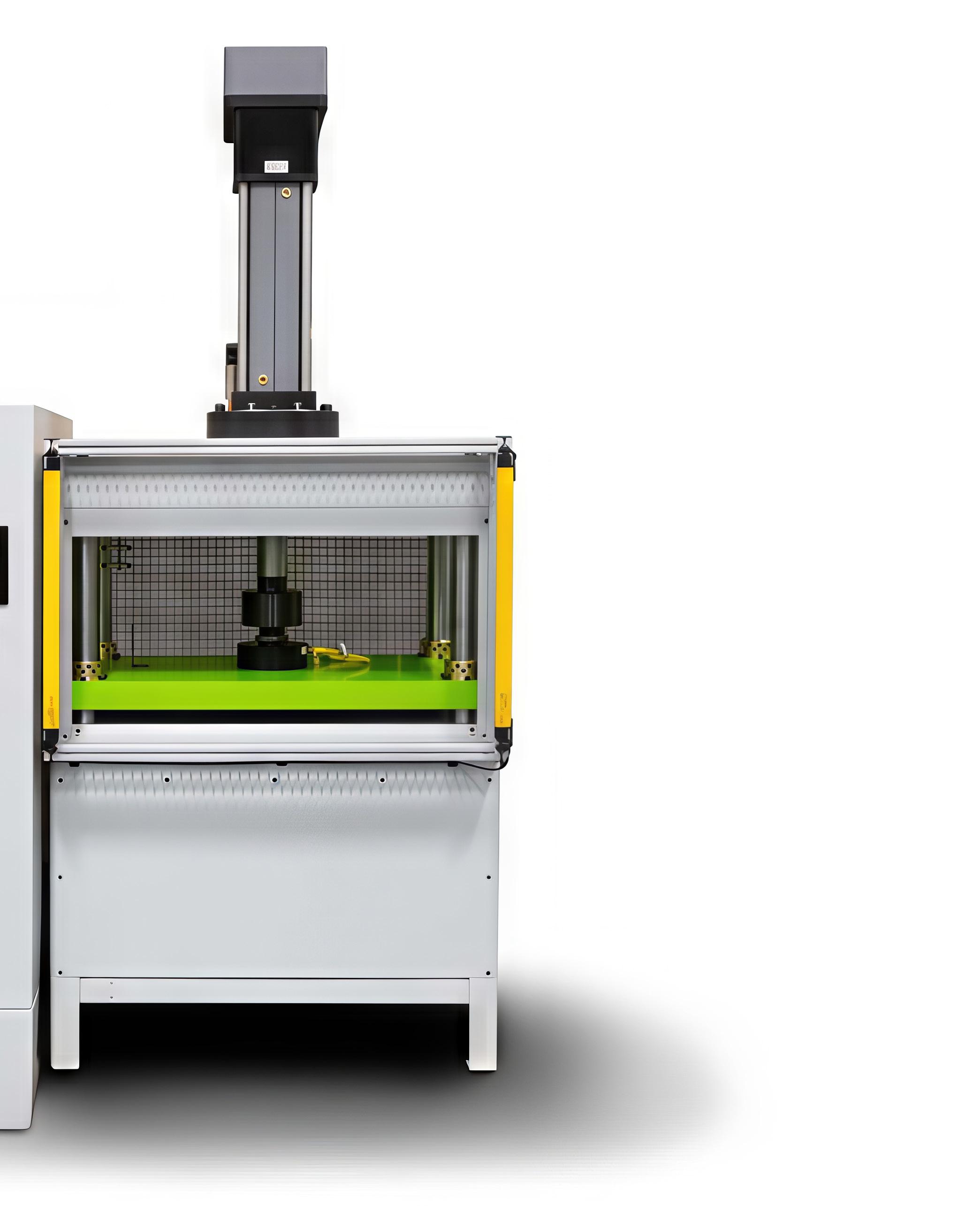
This Freeman Schwabe Machinery cleanroom-ready press is called the Model SEP. It’s targeted to the medical industry with a servo-electric actuator that poses no risk of contamination like fluidpower solutions. Plus, the press uses 75% less energy than comparable presses based on hydraulics.
RELATED:
COMBINING HYDRAULIC AND ELECTRIC-MOTOR STRENGTHS FOR PRESSES
demanding machine tool axes — the ramming axes of a sheetmetal stamping presses, for example — often use gibbed boxways, round-rail linear bushings or splines, or rugged hydrostatic linear guides designed to maintain parallelism even under high dynamic loads.
Hydrostatic linear guides have carriages featuring an internal circuit of pressurized oil that’s regulated by an external system. The carriage rides the linear guideways upon its circuit’s hydrostatic pockets of oil.
Any linear load bearing with profile-rail guides (containing relatively delicate rolling bearing elements) must be very carefully engineered.
No matter the type used, the linear guides on these demanding axes need to maintain parallelism and axiality with the mechanical drive. When paired with a screw-based drive, they must also keep the radial load on the drive nut within allowable values — or integrate with complementary brackets, mounts, and supports to prevent drive-assembly reactions to nonideal loading.
Feedback with hybrid actuation
Digital-transformation (DX) efforts are increasing the need for connected manufacturing. Press equipment now requires actuation with integrated force and position feedback, realtime monitoring, and cyclelevel data collection. This is critical where traceable process data is needed for quality checks and predictive maintenance.
What’s more, manufacturing is moving to more product variety and faster changeovers. Presses must adapt quickly to changing process parameters.
Electric actuation is easier than hydraulic actuation to integrate into software systems for DX and IIoT functions.
For example, programmable hybrid electrichydraulic actuation fits the bill for such flexible production lines with modifiable force, position, speed, and dwell profiles. Output from some of these hybrid actuators is 100 to 150,000 lb precisely controlled to deliver specific positions, forces, speeds, and dwell times set by servolevel programming. Such actuators can even include force and position sensors for realtime cycle traceability, process validation, and automated pass-fail quality checks. Such connectivity also lets operations synchronize multiple hybrid electric-hydraulic actuators on especially high-force applications or machines that need to distribute force across large tooling structures. DW
Linear Motion Tips linearmotiontips.com
Engineered polyurethane isolates delicate parts
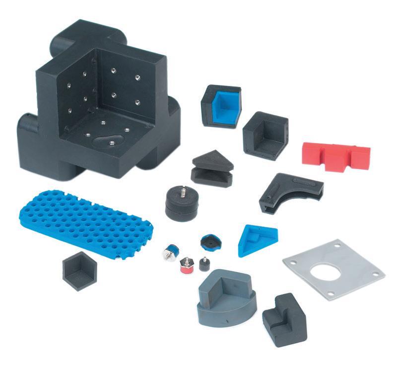
Based in Kent, Ohio, Sorbothane manufactures Sorbothane the material. This engineered polyurethane is a highly damped, visco-elastic polymeric solid that flows like a liquid under load. The company does all its engineering, designing, manufacturing, and sourcing in the U.S.
OEM engineers as well as entrepreneurs integrate the material in all sorts of designs. In fact, Sorbothane has protected the Liberty Bell during transport. It isolates sensitive cameras on space shuttles. It extends the life of manufacturing machinery, and it even isolates delicate lab-testing equipment from outside vibrations.
Here’s how it works: Sorbothane is a patented visco-elastic polyurethane that deforms under load and transmits force in all directions. Its elastic behavior means it returns to its original shape after loading.
As shown in the video here, Sorbothane cups convert energy from hammering into heat — absorbing up
to 94.7% of the shock energy this way. The material can also work as a vibration-damping material, absorbing more than 50% of all vibration energies from 1 to 30,000 Hz.
It’s unique that the material can damp and isolate. In contrast, metal springs and rubber mounts are good isolators but have almost no damping capability. In contrast, oil dashpots can damp but can’t isolate vibration. Foam isolates well but often doesn’t last. Sorbothane outperforms rubber and neoprene in situations that need shock and vibration control.
So, material generates heat through hysteresis and directs energy perpendicularly … for lost energy 90° out of phase from the original disturbance. It reduces shock over a longer period of time for gradual deceleration that keeps delicate equipment safe.
Sorbothane comes in a lot of different forms. For example, an interlocking Sorbothane system is
based on 4-in. x 4-in. Sorbothane pieces that lock together to build custom shock-attenuating and vibrationisolating assemblies. The modular system includes a steel baseplate for column strength and maintenance of shape. Designers can also use a steel top plate.
MORE FROM SORBOTHANE:
For more information, visit sorbothane.com. Also check out the most recent Design World coverage of Sorbothane applications:
SCAN THE QR CODE TO WATCH THE VIDEO
Edited by Mike Santora • Managing Editor
are really costing you
Electric motors are the driving force behind many industrial processes, from pumps and fans to conveyors and mixers. However, while they run in the background, their energy consumption can make up a significant share of operational costs. Understanding exactly what a motor costs to run, and how to reduce that cost, requires more than just looking at the energy bill. Here, David Strain, technical director at systems integrator Technidrive, explains how to calculate motor running costs and highlights ways that businesses can use this information to improve energy efficiency and reduce consumption.
Electric motors account for a significant share of industrial power consumption, making them a major contributor to both operating costs and environmental impact. While buying a motor is a one-time expense, it represents less than 2% of the total cost of ownership (TCO), meaning that the other 98% consists almost entirely of energy usage.
What running costs can tell you
Understanding a motor’s consumption offers financial and operational advantages. Regular monitoring is essential — without it, reducing energy
use is nearly impossible. Tracking consumption not only shows where costs come from but also creates a baseline to spot changes.
The data can also highlight issues that might otherwise be undetected. For example, if a motor consumes 50 kW one week and 75 kW the next, that variation may reflect a problem on the line, a motor that is over or undersized, or differences between processes. Recording trends in motor running costs can provide insights to improve overall efficiency and positively impact the bottom line.
Calculating the cost
Motor running costs are primarily dictated by electricity prices, the power rating of the motor and its annual running hours. It is also important to remember that a motor’s rated power indicates its mechanical output, not the electricity it consumes. A less efficient motor will absorb more input power to deliver the same output, while a highefficiency motor achieves the same output using less energy.
Information needed to calculate running costs can be found on the motor nameplate or via modern energy meters. First, calculate energy usage in kWh by multiplying annual operating time by rated power. Losses can then be factored in using the efficiency rating to estimate total chargeable kWh. Multiplying this by the electricity tariff gives the annual running cost. For example, a 45 kW motor running
continuously at €0.28/kWh could cost over €40,000 per year.
Cost cutting strategies
Once businesses understand how their motors are performing, there are several ways to reduce energy use and operating costs. Consulting with an expert to evaluate the system is a useful first step. One of the most effective strategies is smarter control. By fitting variable speed drives (VSDs), motors can run at the speed the application requires, and even small reductions in speed can deliver significant energy savings.
Correct sizing and careful selection also play a crucial role. A motor that meets the actual demands of the application will operate closer to full load, improving efficiency. Beyond the motor itself, evaluating other equipment is important. For example, switching
from low-efficiency gear units to more efficient alternatives can significantly reduce energy losses.
Maintenance also matters. Worn or poorly functioning components can force motors to work harder, increasing energy consumption. Simple actions, such as switching equipment off when not needed, can also deliver savings without major investment. Together, these strategies show that savings often come from a combination of smarter choices across motors, drives and the wider plant.
The bigger picture
Calculating motor running costs is an important step for any operation looking to manage energy use, reduce expenses, and meet sustainability goals. It allows companies to make informed decisions and identify where improvements can be made.
However, some of the biggest opportunities lie beyond the motor itself. Poor system design, inefficient equipment or insufficient control can all drive up costs. By combining accurate cost calculations with a broader view of systems and processes, businesses can achieve meaningful reductions in both costs and energy consumption. DW
Motor University: Right-angle or parallel-shaft gearmotor?
Mechanically, the most important attribute of the gearmotor is the relationship of the output shaft to the major axis of the unit. Output can be in line, parallel, or right angle, with parallel and right-angle options including hollow shafts. Intuitively, power delivery in line with the motor axis would seem to be the best option, but there are plenty of good engineering reasons to go with a rightangle drive.
The primary one is the available space inside the machine for the gearmotor. There may simply not be enough space for a parallel-shaft orientation, and a right-angle gearmotor is then the only option, or vice versa. Another consideration when choosing the gearbox type is efficiency, with parallel-shaft gearboxes usually being more efficient than right angle. That is because the most common gearing type in a right-angle gearbox is worm gearing.
Worm gearing involves a sliding action between the worm thread and the teeth
of the mating gear. There’s more friction and more heat produced, resulting in a lower efficiency than the meshing action of spur and helical gearing.
Although worm gearing is most common in right-angle components, hypoid gearing is another option … though it’s generally more expensive than worm gearing. Applications that especially benefit from high efficiency include battery-powered mobile machines where a less efficient gearmotor would drain the battery quickly.
The need for a hollow output shaft may be another reason for the machine designer to choose a right-angle over a parallel shaft. Although a hollow shaft can be found in both configurations, it’s more commonly available in a rightangle gearbox by far. A hollow shaft can simplify assembly and reduce the overall machine cost by eliminating couplings where there is already a shaft in the machine.
Bodine Electric offers specialty products in all the formats covered in this video to simplify the design process and improve reliability. There are literally thousands of combinations possible.
For more information, visit bodine-electric.com. Also check out the most recent commentary from Terry Auchstetter of Bodine Electric Co.:
SCAN THE QR CODE TO WATCH THE VIDEO
HOW IS
Automotive in-cabin radar uses 60 (60 to 64 ISM band) GHz or 77 GHz mmWave sensors to monitor vehicle interiors, detecting, locating, and classifying passengers. By transmitting radio waves that reflect off surfaces, these systems can detect micro-movements like breathing and heart rates through blankets or clothing and can provide child presence detection (CPD), seatbelt reminders, and airbag performance optimization. Here’s how it’s done.
Basic in-cabin sensing for applications like occupant monitoring and child presence detection (CPD) previously relied on a variety of sensors including weight sensors, ultrasonic devices and simple ultrawide band (UWB) wireless sensors with a resolution of 3 to 10 cm. Modern in-cabin sensor systems use a single radar sensor to support multiple functions and deliver superior performance (Figure 1).
One of the factors driving the use of advanced sensor technologies
JEFF SHEPARD
USED FOR
are increasingly demanding safety standards from the European New Car Assessment Programme (Euro NCAP), the National Highway Traffic Safety Administration (NHTSA), and New Car Assessment Program (NCAP) in the U.S. That’s resulting in the development of more advanced sensors.
Common applications for radar sensors include (Figure 2):
• Child presence detection (CPD) sends an alert if a child or pet is left alone in the car.
• Smart airbag deployment is used to change airbag force based on occupant size and position.
• Vital signs monitoring can detect driver fatigue.
• Gesture controls are used primarily with the infotainment system to reduce driver distractions.
Some of the considerations when designing in-cabin radar sensors include frequency selection, sensor placement, and the use of integrated sensors versus streaming data to a central electronic control unit (ECU).
60 GHz is currently the preferred choice. It has largely replaced 24 GHz since the higher frequency improves resolution (down to 5 cm) for distinguishing between adults and children and can accurately monitor vital signs. Compared with 24 GHz solutions, 60 GHz radar provides over 20x higher resolution due to a wider bandwidth (up to 5.5 GHz). Using advanced sensing algorithms, 60 GHz can detect
Adobe Stock
sub-millimeter micro-movements, making it capable of sensing human breathing and even heartbeats.
Another choice is 77 GHz (76-81 GHz) that can provide even better resolution and angular accuracy but is currently used primarily in external advanced driver assistance system (ADAS) applications.
Placement of the sensor can be application dependent. Putting the sensor overhead in the headliner is most common and enables a single sensor to monitor the entire cabin and perform a variety of functions. Side mounting in the B-pillar is used for targeted occupant detection and for gesture controls. Vital signs can be monitored and occupants classified using under seat or dashboard mounted sensors.
The choice of physical location includes edge and satellite architecture. In an edge architecture, an intelligent sensor has integrated processing that sends finalized detection data to the ADAS ECU. Satellite architectures, a type of zonal architecture, uses a simpler and lower cost sensor and sends unprocessed data to a centralized ECU over a high-speed Ethernet connection.
Figure 2. Typical applications for incabin radar sensors. Infineon
Figure 1. Comparison of in-cabin multiple sensor architecture (left) with the use of a single radar sensor (right). Lisleapex Electronic
Why not IR or RGB?
Infrared (IR) and visible light (RGB) imaging are also options for in-cabin applications, especially for driver alertness monitoring. They can be used to complement radar but are not generally considered to be substitutes for radar. It’s about more than imaging.
IR and RGB can provide highresolution visual details like facial expressions and eye tracking that are useful for driver alertness. Monitoring radar can support privacy protection while tracking vital signs.
IR imaging typically includes an IR lighting source and provides superior low-light performance but can be subject to interference under bright daylight conditions (Figure 3). RGB imaging can provide better context in daylight but has limitations under low-light or nighttime conditions, without introducing a light source that can be distracting to the driver.
Engineers have developed sensors that capture both spectrums and that combine IR and RGB imaging, enabling systems that use RGB capability during daylight conditions and IR sensing when operating under lowlight or nighttime conditions. That can provide an option to radar for specific use cases, but radar supports the widest range of sensing requirements including CPD, SBR, gesture controls, and so on.
Summary
Automotive in-cabin radar monitors vehicle interiors, detecting, locating, and classifying occupants. These systems can detect micro-movements like breathing and heart rates through blankets or clothing and can provide CPD, SBR, airbag performance optimization, gesture controls and other functions. IR and RGB imaging can be used in certain cases but are not generally considered to be substitutes for in-cabin radar. DW
Figure 3. IR sensors can operate effectively under low-light or nighttime conditions. Anyverse
DEFINING AND MEASURING STRAIN
A metallic foil strain gauge can detect how a test specimen responds when subjected to axial stress.
Rick Nelson • Contributor
In a previous series, we investigated the Wheatstone-bridge circuit topology and described how straingauge elements could be used in the bridge legs.
Q: At that point, I asked the question, what is strain, and what are its units?
A: Right, so we’ll take up that question in this new series. Figure 1 at the top shows a specimen under test of length l. In the center image, we apply an axial stress in the form of tension to the specimen, and it lengthens by an amount Dl. The strain, indicated by a lower-case epsilon, is:
In addition, as shown at the bottom, if you apply axial compression to a specimen, it shrinks in length, and you’ll have a negative strain.
Like the radian, strain is a ratio of lengths and is therefore dimensionless. It can be helpful, however, to think of it in units such as meters per meter.
Figure 1. A test specimen of length l increases by length Dl when subjected to axial tension and decreases by length Dl when subjected to axial compression. Rick Nelson
You’ll also see strain expressed in microstrain, abbreviated µe, which is 1 millionth of e. If you have a specimen 1 meter long and you apply tension that expands its length by 1 micron, you’ll have a strain of 1 µe
Q: OK, given that we’ve defined strain, what’s an effective way to measure it?
A: Just as we can use a thermocouple to measure temperature or an accelerometer to measure vibration, we can use a metallic strain gauge to measure strain. The metallic strain gauge consists of a conductive foil pattern on a flexible insulating backing, such as the one shown in Figure 2, with the conductive foil shown in black and the insulating backing, called a carrier, shown in blue. The image on the left shows the strain gauge in an unstrained state, for which it has a resistance R When a test specimen on which the gauge is mounted undergoes tension, as shown in the center, the vertical conductive elements of the pattern elongate and become thinner, and their resistance increases by an amount DR. Conversely, under compression,
as shown on the right, the resistance decreases by DR.
Q: How do we relate strain-gauge resistance changes to testspecimen length changes?
A: Your strain gauge will have a parameter called gauge factor, abbreviated GF, which you will find on the data sheet. l, usually about 2 for a metallic strain gauge,[1] relates to gauge resistance and specimen length as follows:
Now we can solve for strain as a function of the resistances and gauge factor:
Q: So we just glue the strain gauge to the specimen, and we are all set.
A: Right, but you’ll need to use a special
adhesive, such as cyanoacrylate, methacrylate, or epoxy resin, that can accurately transfer your specimen’s deformation to the strain gauge. Factors that influence which adhesive you use include the strain and temperature ranges[2].
Q: How do we measure strain using the Wheatstone bridge?
A: Figure 3 is an alternate view of Figure 2 from part 4 of our previous series. Here, RX is an active strain gauge, and R2 is a dummy strain gauge used for temperature compensation. Note that the long, thin wires of R2 are mounted perpendicular to the direction of tension, so their resistance is unaffected by the strain, and you will not need a special adhesive. However, if you use two different adhesives, you should ensure that their thermal properties are similar.
Q: So how do we calculate strain?
2. A metallic
presents an increase in resistance under tension
and a decrease in resistance under compression
A: We’ll look at the details of the calculation next time, after which we’ll discuss some additional strain-gauge considerations. For example, Figure 3 shows a half-bridge application with one active strain-gauge element, but other configurations are possible. We’ll also look at optimizing the excitation voltage (VIN in Figure 3). Finally, straingauge applications often involve large structures, such as wide-body airframes, antenna towers, stadiums, buildings, or bridges, so we’ll look at lead-resistance and signal conditioning considerations. DW
Figure 3. In this configuration, RX is an active strain gauge element, and R2 is a dummy used for temperature compensation. Rick
Figure
strain gauge (left)
(center)
(right). Rick Nelson
Nelson
Many manufacturing inefficiencies start at the design stage, but are uncovered on the shop floor. This special section offers engineers a refresher on design for manufacturability (DFM), from its origins and core principles to the mindset and digital tools that define modern practice.
goal of DFM is to create products that are easier, faster, and more cost-effective to manufacture while maintaining quality and functionality.
The
Adobe Stock
DFM’s history and core principles A mindset in the making:
RACHAEL PASINI • EDITOR-IN-CHIEF
It’s no secret that manufacturing problems and quality issues can originate during the design phase. Choices about components, materials, and assembly methods made early on can affect production and downstream processes. Design for manufacturability (DFM) aims to prevent expensive errors and boost efficiency throughout product development cycles.
Design for manufacturability isn’t new. Its conceptual roots can be traced back to the 16th century, but it really took off during the First Industrial Revolution (c. 1760 to 1840), when machines started replacing hand-made production. Honoré Blanc and Eli Whitney are known for developing musket production systems and accompanying machine tools that enabled standardized parts to be easily interchanged.
This way of thinking paved the way for the forever influential Henry Ford and Frederick Winslow Taylor, two of the major frontrunners during the Second Industrial Revolution (c. 1870 to 1914), when apprenticeship models were replaced by assembly-line production. During that period, we also saw the first Gantt Chart; time and motion studies became a popular way to measure production and identify areas to increase efficiency and reduce costs; and World War II accelerated assembly lines, requiring even more efficiency, productivity, and cost savings.
The outcome of all that (plus many other factors) led to a phase in which large companies built their own rubrics and methods to measure themselves. Academic researchers also took an interest, and starting around the 1950s or 1960s, as we entered the Third Industrial Revolution (started c. 1950s), or the Digital Revolution or Information Age, these researchers conducted studies, wrote books, taught classes, and consulted large companies on best practices.
Geoffrey Boothroyd is often credited with popularizing design for manufacturing and assembly (DFMA). He wrote and co-authored many books and, in collaboration with others, created the first software program that gave design engineers immediate quantitative feedback on how their decisions affected assembly time and part count. His work helped reduce costs for many large organizations across industries and transformed modern manufacturing.
This is the period when manual processes started relying on computing and automation. Important milestones include: the internet was invented; the first accessible CAD software was released in the 70s; 3D printing started in the early 80s; finite element analysis became more accessible in the 80s and 90s (which enabled our modern-day “shift-left” mentality); parametric 3D
modeling software, including Pro/Engineer and Solidworks, was released; PLM systems also emerged — the list goes on.
As we moved into the 2010s, cloud-based CAD/CAM systems such as Autodesk Fusion 360 and Onshape were released, ushering in the Fourth Industrial Revolution (started c. 2016), Industry 4.0, or the Intelligence Age, in which digital twins and AI made their big entrances. Now, we’re at the dawn of applying agentic AI, where humans are above the loop and execute multiagent systems at scale.
Though this walk down memory lane omits hundreds (if not thousands) of important milestones and people, the point is that in a relatively short time, humanity has made leaps and bounds, yet an underlying challenge remains: How can we design parts and products
so that they can be manufactured efficiently, cost-effectively, and especially these days, sustainably?
CORE TENETS OF DFM
The goal of DFM is to create products that are easier, faster, and more cost-effective to manufacture while maintaining quality and functionality. The expected outcomes and benefits include, but are not limited to:
• Simplified supply chain by standardizing and reducing parts
• Improved sustainability by reducing material waste and energy consumption
• Better collaboration between design, engineering, and manufacturing teams
• Increased customer satisfaction through higher quality products at competitive prices
In 1913, Henry Ford implemented the first automotive assembly line at the Highland Park plant in Michigan. The new process enabled workers to assemble the Model T in 90 minutes.
The goal breaks down into several interconnected objectives:
• Reduce costs: Choose and use materials wisely, cut down on waste, make processes simpler, and reduce assembly time and complexity to keep production costs down.
• Improve quality: Remove features prone to defects, limit variations, and plan for inspections to ensure parts are consistent and reliable.
• Accelerate time-to-market: Minimize design changes and manufacturing delays by planning carefully and addressing issues early on.
• Improve manufacturing efficiency: Ensure designs align with existing manufacturing capabilities to reduce reliance on special tooling or equipment that adds cost and complexity.
• Reduce risk: Find and fix potential manufacturing problems during the design phase rather than waiting until production, when fixes are more expensive.
Many organizations have established methodologies that companies can adopt and customize. To be honest, they can look rather generic and suspiciously similar to other design approaches. However, a key difference is in the implementation.
Instead of following a strict step-by-step process where
engineers gather requirements, design a part, finish the design, and then pass it to manufacturing — sometimes only to have it rejected or blamed for high costs or rework — design engineers are encouraged to learn about manufacturing capabilities and work closely with manufacturing engineers and machinists as they develop designs. Once both teams agree the design is ready to test, they can start prototyping and testing, using feedback to iterate and improve the design as needed. Only when everyone involved agrees that the design meets requirements and can be made efficiently is it considered final.
Other methods may include more detailed steps for requirements gathering and early field analysis. They may also separate computer-aided engineering (CAE) testing from physical and quality testing, and include steps for deployment and support teams to complete the process.
Companies and teams can pick the method that works best for them. Some prefer a simple approach that matches lean engineering principles, while others need or want detailed steps for careful tracking and traceability.
No matter what steps or diagrams are used, the most important part of
IN A RELATIVELY SHORT TIME, HUMANITY HAS MADE LEAPS AND BOUNDS, YET AN UNDERLYING CHALLENGE REMAINS: HOW CAN WE DESIGN PARTS AND PRODUCTS SO THAT THEY CAN BE MANUFACTURED EFFICIENTLY, COSTEFFECTIVELY, AND ESPECIALLY THESE DAYS, SUSTAINABLY?
In 1963, Ivan Sutherland developed Sketchpad at MIT. This was the first program to use a graphical user interface and set the stage for future CAD software.
THE MOST IMPORTANT PART OF DFM IS HAVING THE RIGHT MINDSET AND EMBEDDING IT IN ENGINEERING TEAMS.
DFM is having the right mindset and embedding it in engineering teams. Some team members may naturally think this way, while others might need training and coaching to get there.
DESIGNING FOR “X”
Aside from DFM, there are numerous design approaches that engineering teams can implement, depending on their priorities, including:
• Design for assembly (DFA)
• Design for manufacturing and assembly (DFMA)
• Design for reliability (DFR)
• Design for cost (DFC)
• Design for sustainability (DFS)
• Design for additive manufacturing (DfAM)
In general, teams can develop methodologies to design for “X,” where “X” is the company’s top priority, which
can certainly overlap with and include other approaches.
However, engineers will not truly learn DFM, or any other method, by thinking their initial designs are perfect and ready for manufacture. The learning happens through strategic iteration — by thoughtfully designing, redesigning, and continually refining based on manufacturing feedback before handing off.
Remember, the end purpose of design is not to make a prototype. More likely, the purpose is to make hundreds or thousands of a part. Boothroyd defined DFM as “a methodology and set of practices for designing parts so they are easy to produce, consistent in quality, and economical at volume.” One of the key phrases there is “at volume.” This production-scale thinking fundamentally changes design decisions. DW
Today’s software tools help engineers perform cost and manufacturing analyses efficiently with real-time information. Boothroyd Dewhurstk
Experts say, don’t put the cart before the horse
Design engineers need a strategic approach to prevent costly downstream surprises. They aren’t designing for manufacturability in general, but for the manufacturing capabilities and processes available. In addition to having the right knowledge, they need to adopt the right mindset and take a big-picture view to evaluate the impact of their work.
Design for manufacturability is a mindset before it's a methodology. Engineers who treat it purely as a checklist or a software feature — something that occurs when the tool flags a problem — miss the point. DFM has to be internalized, and that requires a bit of intellectual humility most engineers aren't taught to practice: the willingness to assume your design isn't as producible as you think it is. That assumption is harder than it sounds, and the only way to learn it is by designing, getting it wrong, and redesigning — not by reading about
RACHAEL PASINI EDITOR-IN-CHIEF
Experts agree that DFM is more than a methodology and a late-stage checklist. Teams need to keep the end state in mind from the outset and understand how production realities influence design decisions. Adobe Stock
it once and moving on. The discipline compounds over time, which means the engineers who get good at it are the ones who stay curious about manufacturing long after their formal education ends.
Part of that curiosity is thinking at production scale from the start. Designing a prototype and designing a production part are different cognitive exercises — designing for one part provides a proof of concept, whereas creating a thousand parts is the result of a business decision. Tolerances, material choices, assembly sequences, and part counts all look different when thinking about a line running at volume rather than a machinist making one-offs. Shifting to that frame early — before the design is finalized and locked — is one mental shift that separates engineers who practice DFM from engineers who default to checklists.
The tools available today are genuinely useful. Simulation, generative design, digital twins, AI-assisted validation — they can catch problems faster and earlier than many humans could. However, such tools assume manufacturing knowledge and provide the right answers only when the engineer asking the questions already understands the manufacturing realities behind them. DFM as a mindset is what makes those tools worth using.
DFM INSIGHTS FROM LEADERS AND ENGINEERS
During interviews in the first half of 2026, a number of engineers and leaders weighed in on what they’re seeing in industry, specifically on how DFM isn’t just a checklist or a method — it’s also very much a mindset shift and even a culture shift across an organization. Here are some of their insights.
Many engineers still think of DFM as a checklist or late-stage review. From your experience, what does it mean to treat DFM as a mindset aside from a methodology?
Caroline Cloutier: A DFM mindset is adopted when the end state is kept in view from the very beginning and the realities of production and operation are allowed to shape decisions before designs are finalized. Many industrialization challenges are driven less by how complex a design appears than by how sensitive it is to small variations once repetition begins. That way of thinking draws attention to robustness, efficiency, and repeatability, along with the real capabilities and limits of the equipment that will ultimately build and run the system. It also shapes the sequence and timing of commitment, not just whether a design can ultimately be manufactured. This perspective does not replace formal reviews or governance; it adds context by encouraging assumptions about system behavior and constraints to be examined early, while choices are still flexible.
Technology industrialization executive
general industry observations.
William Parrish: When DFM shows up as a checklist, it usually means the design is already emotionally locked. Everyone agrees it’s “done,” and now the unspoken objective is to get it through manufacturing without having to revisit any of the decisions that mattered. Treating DFM as a mindset means you don’t let that separation happen in the first place. You’re thinking about how something will actually be built while you’re still designing it. Who touches it. What they’ll struggle with. Where variation is going to creep in even if the drawing looks clean. Manufacturing reality isn’t something you reconcile at the end. It’s part of the design work itself, whether that’s comfortable or not.
Shane Kenyon: At Supersede, DFM starts at the same time as design. We don’t separate “design” from “how
this will be made.” Material behavior, process limits, handling, and scale are considered from the first CAD decisions, not reviewed at the end. When DFM is treated as a mindset, design choices are naturally constrained by what can be produced repeatedly on real equipment, not just what is theoretically possible.
Marco Tinner: Treating DFM as a mindset means thinking about fabrication from the very first design or prototype step. Many design decisions are not purely performance-driven; they depend heavily on how an optical system will be manufactured. Questions such as whether two spherical lenses are preferable to an asphere, or where the risks lie in each option, need to be addressed early. In the end, the goal is the most cost-efficient solution that still fulfills performance requirements.
Without this early manufacturing perspective, DFM becomes a late correction rather than a guiding principle.
Modern design teams rely heavily on digital tools such as simulation, model-based design, and digital twins. How do these technologies enable better DFM, and where might they give teams a false sense of confidence?
Cloutier: Simulation, model-based design, and digital twins have become central to modern design practice, allowing teams to explore system behavior long before physical assets exist. Their impact on DFM is strongest when they are used to investigate how designs respond under a range of conditions, rather than to validate expected performance. Many industrialization challenges do not appear at expected conditions, but at the edges of operating distributions where models are least often examined. Manufacturability tends to become visible as systems encounter transients and sustained operation over time, where behavior evolves rather than remaining static. Applied with that intent, digital tools help accelerate learning without implying certainty, supporting engineering judgment rather than replacing it.
Parrish: Digital tools help because they let you get answers before you’re committed. You can see pretty quickly when something is only working because the model is clean and the conditions are perfect, which saves a lot of wasted motion. The confidence problem is that the model doesn’t carry the variables of reality. It doesn’t include how a fixture actually behaves after it’s been used for a while, or how setups drift depending on who’s running the shift, or what tooling wear does to the result over time, or how a supplier “adjusts” the process to keep the schedule intact. You can be looking at something that appears stable in the
digital world and still be signing yourself up for a part that’s finicky in production and takes constant attention to keep inside spec.
Kenyon: We rely heavily on tools like Catia, 3DExperience, and Altair’s simulation suite to explore geometry, material behavior, and sensitivity early in the design process. These tools are excellent for narrowing the design space and quickly understanding tradeoffs. Where teams seem to get into trouble is treating simulation output as truth instead of a starting point. Without constant correlation to manufacturing and test data, even sophisticated models can hide real process variability, or too much time is spent on that model. At Supersede, digital tools are part of a closed loop — models inform builds, builds inform testing, and test data feeds back into the model.
Tinner: In optics, fabrication is inherently complex. For inexperienced engineers, it is almost impossible to know all the manufacturing rules and potential pitfalls up front. Digital tools help by significantly accelerating the learning curve. For experienced users, they act as digital sparring partners and increase confidence in design decisions. Across many projects, we consistently see that manufacturability is ultimately defined by the workshops producing the parts, which always have the final word. Digital tools cannot replace this, but they greatly improve communication and alignment, resulting in faster and smoother projects.
What is one manufacturability issue you consistently see overlooked, even by experienced engineering teams, and what are the downstream consequences?
Cloutier: Systems often behave differently once they move into sustained operation, with changes that accumulate gradually rather than appearing all at once. Manufacturability rarely fails in a single moment; it more
often shows up as a steady increase in the effort required to keep the system running as intended. Recognizing manufacturability as dynamic rather than static helps explain why early confidence does not always translate into long-term ease of operation.
Parrish: Tolerance stacking across multiple operations, especially when more than one vendor or process is involved. Each tolerance usually makes sense in isolation, so no single decision looks wrong. But once they stack, the part only works if everything lines up perfectly, which we know rarely happens. What follows is rework, adjustment, or quality issues that get framed as execution problems, even though the design made success fragile from the very start.
Kenyon: Process-driven variability is often underestimated. Designs are frequently optimized around nominal conditions without fully accounting for how manufacturing variation impacts performance. Downstream, this leads to inconsistent results, late-stage fixes, and an overreliance on inspection or rework. Designing around process capability instead of ideal conditions is one of the biggest levers for improving yield, consistency, and qualification success.
Tinner: One issue we consistently see across many projects is that not all parameters required for fabrication or testing are fully specified on the lens drawing, even in experienced teams. Important manufacturing or metrology details are often implicit rather than explicit. This leads to repeated back-and-forth between design and manufacturing to clarify requirements. As a consequence, lead times increase and both development and fabrication become less efficient.
In successful organizations, how is responsibility for DFM shared across design, manufacturing, and supply chain teams? What breaks down when DFM is treated as a handoff?
Cloutier: DFM reflects how different perspectives intersect early in the development process. Many of the most persistent manufacturability challenges arise at interfaces between components, processes, or organizations, rather than within individual parts or disciplines. Inputs from design, manufacturing, operations, and supply chain tend to be most influential when decisions are still reversible. Challenges typically stem not from a lack of expertise, but from the timing of insight relative to when decisions harden. When key architectures are fixed, complexity shifts from something that can be influenced through design to something that must be accommodated in operation. Manufacturability and operability then become properties of the overall system, shaped by how and when decisions are integrated.
Parrish: In teams that handle DFM well, responsibility is shared early and informally. Manufacturing input isn’t reserved for a formal review at the end. Supply chain concerns show up before designs are frozen, not after quotes come back with bad news. When DFM turns into a handoff, it becomes reactive. Design moves on. Manufacturing compensates. Supply chain absorbs cost and risk. Everyone feels like they’re cleaning up after someone else, and trust erodes even though no one intended to create the problem.
Kenyon: At Supersede, DFM is shared naturally because we’re a small, hands-on team. Design, manufacturing, testing, and sourcing aren’t separate functions — they’re overlapping responsibilities. The same people designing parts are running equipment, troubleshooting issues, and seeing firsthand where assumptions break down. That shared experience creates alignment without formal handoffs. When DFM is treated as a handoff, problems get abstracted, and ownership is diluted. Teams stop learning from each other, and
manufacturing ends up compensating for decisions made in isolation. A hands-on, co-mingled team with the right mindset closes that gap quickly and continuously.
Tinner: In successful organizations, DFM responsibility is shared across design, engineering leadership, product management, and even sales. Modern digital tools, such as PanDao, allow people who are not optical designers to evaluate manufacturability early in the design process. This ensures that project leads have continuous visibility into cost and risk, and that sales teams are better prepared for discussions with optical suppliers. When DFM is treated as a handoff from design to manufacturing, critical issues are often discovered late, which can cause projects to fail or incur substantial additional costs.
For teams moving quickly or operating with limited resources, what is one practical habit or question that can dramatically improve manufacturability without slowing development?
Cloutier: One practical habit that consistently improves outcomes is anchoring decisions around how a system behaves once repetition begins. A simple question is often sufficient: “Would this still function acceptably if inputs vary and the system needs to run continuously over time without exceptional effort?” This question is most useful at moments when decisions reduce flexibility and learning must be deliberate. It helps teams surface gaps in understanding and recognize when additional commitment may narrow options prematurely or create the next opportunity for learning. The intent is not to delay commitment indefinitely, but to recognize when commitment would outpace what the system has revealed so far. Teams that scale well learn to treat commitment as something that is earned through evidence, allowing industrialization to move
forward with confidence rather than momentum alone.
Parrish: Before locking a design, be honest about what the hardest step to build actually is, and who ends up owning that step day to day. If the answer is fuzzy, or theoretical, the design probably isn’t ready yet. This doesn’t slow teams down in practice but it avoids the much slower kind of learning that happens later, when parts are already on the floor and people are forced to defend decisions instead of improving them.
Kenyon: One practical habit is to get out on the floor and run the process yourself. At Supersede, we take a cradle-to-grave approach that isn’t just confined to the product, but present throughout the manufacturing process and in the factory itself. The hands-on understanding gained from running equipment and handling parts exposes assumptions that no amount of modeling alone will catch. In practice, this shortens development time because problems are addressed early instead of being discovered after scale-up.
Tinner: A simple but effective question is: “Can this design be fabricated as intended, and do we understand where the risks are before sending it to a supplier?” Optical fabrication is complex, and without early validation, this often leads to costly back-and-forth or reliance on expensive external expertise. A quick digital manufacturability check can replace many of these iterations and significantly reduce risk and lead time.
DOES YOUR TEAM HAVE A DFM MINDSET?
Experts agree that DFM is more than a methodology and a late-stage checklist. Teams need to keep the end state in mind from the outset and understand how production realities influence design decisions. Once designs are scaled up and mass-produced, teams see how good the design really is in the
OVERALL, ENGINEERS NEED A MINDSET SHIFT AND A BETTER UNDERSTANDING OF THE RANGE OF MANUFACTURING CAPABILITIES AVAILABLE TO DETERMINE WHICH ONES MAKE THE MOST SENSE.
face of slight variations that can occur in production.
Though engineers may have exposure to DFM in their undergraduate coursework, companies often end up having to teach and enforce it as part of on-the-job training. Most engineers end up learning DFM through experiences — often uncomfortable experiences and interactions — because the DFM mindset hasn’t yet sunk in. However, that’s not limited to entry-level engineers. It can apply to anyone and require a major cultural shift for some companies, where teams are often siloed and geographically dispersed, communication isn’t fluid, and maybe relationships aren’t highly valued.
After scouring forums and asking experts, the punchline is that communication is key. Design engineers need access to the shop floor and actually talk to the machinists who will be manufacturing their parts. They don’t need to know everything about manufacturing, but they do need at least a baseline understanding of the capabilities within their company or the technologies they have access to. They also need access to people with expertise. Overall, engineers need a mindset shift and a better understanding of the range of manufacturing capabilities available to determine which ones make the most sense. DW
RACHAEL PASINI • EDITOR-IN-CHIEF
Agentic AI is the next big thing
Design engineers are under more pressure than ever to design faster, design smarter, and shift-left problems before they become expensive downstream. Leaders and managers expect AI to be part of workflows now to increase daily efficiency and reduce costs. But at the same time, supply chain disruptions, material costs, tariffs, workforce shortages, and the constant need to reskill teams are creating real strain that no amount of AI enthusiasm fixes. Manufacturing is feeling it, too. Everyone is trying to get a competitive advantage in this fastpaced, dynamic world, and they’re increasingly using AI to get ahead.
AIis a broad topic, but thinking of it as concentric circles helps simplify the main idea. In the largest circle, AI is the overarching term to describe algorithms that help computers think like humans. They synthesize information, solve complex problems, and can make decisions. Machine learning is a subset of AI that uses advanced algorithms so that computers can “learn,” meaning adapt to change and new data, either under human supervision or unsupervised. Deep learning is what it sounds like — more advanced algorithms that use neural networks for even more in-depth data analysis, pattern recognition, and complex problems. And then we have generative AI, which includes ChatGPT and other chatbots that humans can communicate with to potentially gain knowledge and serve as assistants or colleagues to accelerate work tasks. Today’s hot topic is agentic AI, which takes generative to a whole new level. Design World moderated the Future of Engineering Summit on March 25, 2026, where experts gathered to discuss agentic AI in engineering workflows, why agentic AI projects usually fail, and how they can give teams and companies a competitive advantage. Ryan Qi, principal worldwide business development and go-to-market leader
for AWS, discussed the difference between generative AI and agentic AI, emphasizing that humans need to be above the loop, rather than in the loop, for agentic AI to be worthwhile. He shared how generative AI, such as ChatGPT and similar algorithms, can generate content. Humans ask it a question or give it a prompt, and it synthesizes a lot of information to provide an answer or output. Humans need to be highly involved in the conversation to guide and coach generative AI, prevent or correct hallucinations, and ensure outputs make sense. With agentic AI, the point is for humans to be less involved in the details and provide oversight while one or more agentic AI systems do all the heavy lifting. The idea is for teams to scale with multi-agent systems capable of autonomous decision-making that goes on in the background.
AUGMENTING WORKFLOWS WITH AI-ENABLED DIGITAL TOOLS
As many highly experienced workers retire, a huge knowledge gap remains with fewer people to turn to. Generative AI comes into play here to help capture, retain, and build upon that knowledge so that anyone in the company who needs the knowledge has access to it. However, manufacturing is also augmenting its workforce with automation to offset
Remember that simulation, generative design, digital twins, and AI-assisted validation tools can catch problems faster and earlier than many humans can, but they still require engineers who understand the manufacturing realities behind them. Adobe Stock
declining employment, which changes the skill sets and knowledge required.
According to Deloitte’s 2026 Manufacturing Industry Outlook, survey results showed (perhaps unsurprisingly) that manufacturing employment is decreasing, the cost of employment is increasing, and the cost of materials and components is increasing. The survey also showed that more manufacturers are implementing smart manufacturing, automation, robotics, and digital tools, especially AI — all of which require upskilled workers and add more knowledge that needs to be transferred or communicated to design engineers.
On the design side, AI-enabled digital tools also come in as augmentation and to help accelerate product development while reducing downstream risks and costs. Here is a list of the types of digital tools available:
• CAD-integrated DFM checkers: Software that runs inside or alongside the CAD environment and evaluates
geometry against manufacturing rules in real time — wall thickness, draft angles, undercuts, tolerance stacks, weld accessibility. These are the original "shift-left" DFM tools, historically rules-based and increasingly AI-enabled.
• AI-assisted design validation: The next generation of the above. Rather than relying on a fixed rule set, these tools learn from production data and prior designs to flag issues that a static rule set probably wouldn’t catch. They also increasingly propose fixes rather than just flagging problems.
• Generative design: AI-driven generation of geometry from a problem specification, including load case, material, manufacturing process. This produces topologyoptimized parts that are inherently shaped for the constraints of how they'll be made.
• Digital twins: Virtual replicas of a
part, a process, a production line, or an entire facility. In DFM specifically, the high-value use cases are virtual commissioning and process tuning.
• Integrated simulation environments: FEA, CFD, moldflow analysis, and tolerance analysis running inside or tightly coupled to the CAD software. These catch structural, thermal, and flow problems before prototyping.
• Cost-estimation and "should-cost" tools: Software that estimates manufacturing cost from a 3D model, including material, labor, tooling, and process. These are increasingly AI-driven and close the loop between design choices and economic consequences in real time, which is especially helpful in today’s dynamic economy.
• Additive-manufacturing-specific DFM: Tools focused on 3D printing that provide printability checks, support structure optimization, build
A breakdown of artificial intelligence, machine learning, deep learning, and generative AI. PopovaZhuhadar via Wikimedia Commons
orientation analysis, and thermal distortion prediction. This is a specialized branch with its own rule sets.
• PCB and electronics DFM: A whole parallel ecosystem for printed circuit board design to evaluate solder pad spacing, drill alignment, thermal relief, and panelization. This is conceptually similar to mechanical DFM but with different rules and tools.
• Instant quoting and designfor-supply tools: Browserbased platforms, especially when working with contract manufacturers, where a designer uploads a file and gets immediate manufacturability feedback plus a quote. These have democratized DFM for small teams and prototype work.
• Agentic AI for manufacturing workflows: The newest category, and the one Deloitte is flagging hardest for 2026. These are AI agents that can reason across multiple systems, such as CAD, ERP, supplier databases, and MES, and take autonomous action. In the DFM context, agents can flag a manufacturability issue, propose alternative suppliers, quantify cost impact, and queue up the change order for human approval.
AGENTIC AI IN PRACTICE
As a real, live, working example of agentic AI, during the Future of Engineering Summit, Marc-Florian Uth, senior applications engineer and strategic partnerships lead at Synera, gave a presentation on agentic AI’s ability to help design engineers run manufacturing and cost analyses to streamline the communication that multiple teams would need to have to come to conclusions. In Uth’s example, we saw a tool that looks very similar to a generative AI tool, except it requires little human prompting or interaction. It’s using multiple datasets to synthesize, and the human is still above the loop — the human worker
can still make the ultimate decision. To view all sessions from the summit, visit www.future-of-engineeringsummit.com/recap/spring-2026
In other news, our sibling publication Engineering.com recently reported that Siemens and Xometry partnered up on an ondemand manufacturing marketplace that will soon be integrated into Siemens Designcenter. This is an example of a real-time quoting and DFM feedback tool that will be embedded into a product design platform. They also have a website with the same information, but embedding it into a platform can pool more information in one space and speed things up further.
Our team at Engineering.com also shared a case study on how Acme Space used three AI agents to generate new designs, analyze them, and make sure they’re manufacturable. They claim to have found a solution to AI hallucinations by using a multi-agent system, where successive stages of AIs check each other’s work, and then human engineers complete the final design. The company says that system and process has dramatically shortened development timelines with a fraction of the engineers of a traditional aerospace company.
In another aerospace example, the DLR Institute of Structures and Design in Germany, developed a fully digital process for designing, manufacturing, and assembling aircraft cabin components to enable faster, more flexible production. They call it DiCADeMa, which stands for Digital Cabin Architectures and Design for Manufacturing, and leverages software and robotics to determine mounting positions of cabin compartments.
In summary, DFM has always been about designing with the end in mind, and with agentic AI now reasoning across entire workflows, that end is coming into view faster than ever. DW
DFM REFRESHER FOR ENGINEERS WRAP-UP
Consider taking away these four main points:
1. Design for manufacturability is a mindset and a methodology, not a software license or a last-minute checklist. The tools are getting remarkable, but they don't replace the discipline, and they certainly don’t replace the mindset and cultural shifts that engineers and teams need.
2. Engineers need manufacturing knowledge. This is an ongoing challenge, and the teams getting the most value from digital tools are those in which designers have a decent sense of what will happen to their design on the shop floor and how it will perform given the realities of the shop floor and potential variations in production.
3. Digital tools can augment people and knowledge, but they can do more. AI can certainly help assist with workforce shortages and capture knowledge, but teams that can scale multi-agent AI systems and create reliable digital twins gain a huge competitive advantage. But it’s not just about buying software; it’s about pairing good tools with engineers who know what to do with the output.
4. Humans need to stay above the loop. Not in the loop — above it, monitoring and being accountable for the final decisions. Engineering judgment is still the most valuable thing on the team.
And if it helps, here are four corresponding questions worth bringing back to your team:
• Do we have the right mindset? Is DFM treated as a discipline and a guiding principle, or is it something we hope happens automatically when the software tool flags something?
• Do we have the right methods? Is there a defined workflow, or is everyone doing it differently? Does the company or team have a clear methodology?
• Do we have the right knowledge? And what happens to it as our most experienced engineers retire?
• What digital tools actually make sense for us? Not for the company in a case study, but for our products, our volumes, our suppliers, and our team?
Design for Manufacturability in 2026: How Digital Tools Improve Scalability and Success THIS CONTENT IS ALSO AVAILABLE IN AN ON-DEMAND WEBINAR. REGISTER HERE:
Ryan Ashdown rashdown@arrowfly.com 216.316.6691
Jami Brownlee jbrownlee@arrowfly.com 224.760.1055
Ashley Burke aburke@arrowfly.com 737.615.8452
Tom Duggan tduggan@arrowfly.com 773.724.1638
Mike Francesconi mfrancesconi@arrowfly.com 630.488.9029
Jack Gillerlain jgillerlain@arrowfly.com 773.909.2718
Adrian Nash anash@arrowfly.com 416-500-6906
Susan Powers spowers@arrowfly.com 708.341.3370
Judy Pinsel jpinsel@arrowfly.com 630.538.2638
Melissa Roberts mroberts@arrowfly.com 440.666.3111
CFO Ken Gradman kgradman@arrowfly.com 773.680.5955
DESIGN WORLD does not pass judgment on subjects of controversy nor enter into dispute with or between any individuals or organizations. DESIGN WORLD is also an independent forum for the expression of opinions relevant to industry issues. Letters to the editor and by-lined articles express the views of the author and not necessarily of the publisher or the publication. Every effort is made to provide accurate information; however, publisher assumes no responsibility for accuracy of submitted advertising and editorial information. Non-commissioned articles and news releases cannot be acknowledged. Unsolicited materials cannot be returned nor will this organization assume responsibility for their care.
Subscription Rates: Free and controlled circulation to qualified subscribers. Non-qualified persons may subscribe at the following rates: U.S. and possessions: 1 year: $125; 2 years: $200; 3 years: $275; Canadian and foreign, 1 year: $195; only US funds are accepted. Single copies $15 each. Subscriptions are prepaid, and check or money orders only.
Subscriber Services: To order a subscription or change an address visit our website at: www.designworldonline.com
DESIGN WORLD (ISSN 1941-7217) USPS PUBLICATION #25146 is published 11 times per year: January, February, March, April, May, June, August, September, October, November, December by: Arrowfly; 1111 Superior Ave., Suite 1120, Cleveland, OH 44114. Periodicals postage paid at Cleveland, OH & additional mailing offices.
POSTMASTER: Send address changes to: Design World, 1111 Superior Ave., Suite 1120, Cleveland, OH 44114
Technical Thinking
By Mark Jones
Technical thinking: Backyard laser weaponry
I’m a bit surprised this didn’t get more press. We’ve crossed a long-promised threshold. For the first time, laser weapons were successfully deployed in combat to down drones. Laser weapons are finally doing what science fiction promised. But it was a laser weapon for deployment closer to home that caught my attention. Imagine a mosquito-free evening thanks to an AI-guided laser system — the Photon Matrix.
Living in Michigan is like existing in a swamp. This time of year, crop dusters crisscross my property spraying Bacillus thuringiensis israelensis, Bti, a soil bacterium that's become the biological weapon of choice for mosquito control. It isn’t enough.
Mosquitoes make being outside at dusk (or anytime later) unbearable. Sometimes the days are unbearable too. The county mosquito control resorts to insecticides. Fogging trucks come through after dusk because it’s prime time for mosquitoes and when pollinators are done for the day. The insecticides sprayed are indiscriminate. They are quite toxic to all insects, freshwater and estuarine fish, invertebrates, and sediment organisms. Pollinators are a worry, too. The flowering trees in our yard used to be buzzing this time of year. They are silent now, consistent with the more than 60% drop in pollinators observed in Michigan over the past 15 years.
Mosquito Control was at an event I attended, and I’ve got a bit of a bone to pick. They were almost bragging about using an insecticide based on chrysanthemum flowers. That is a stretch. They aren’t using a manufactured copy of natural pyrethrins, the compounds found in chrysanthemums. They are
using permethrin — a synthetic pyrethroid that, while it has some structural similarities to natural pyrethroids, is multiply chlorinated to make it more toxic and longer lasting. Nothing in nature makes that structure.
It gets worse. Ticks are now a growing concern, and 2026 is predicted to be a record tick year. Treating property against ticks and mosquitoes is a growth business. I asked a couple of local services what they sprayed. In all cases, chrysanthemums were mentioned. Again disingenuously. The insecticides were multiply fluorinated to be more potent and longer lasting. They were PFAS. No chrysanthemums make PFAS. And it is applied in daylight, when beneficial insects are more likely to be exposed.
I don’t like a nightly bloodletting, but I don’t like adding to environmental PFAS either. I’ve tried various types of technology. We had one device that emitted CO2 to attract mosquitoes and vacuumed them up. Were it not for the collected corpses, we couldn’t tell it was functioning. The thought of a laser system shooting mosquitoes out of the sky is strangely appealing.
The units aren’t available for purchase. The Photon Matrix touts a high-precision infrared laser system, invisible and silent. Mosquitoes are detected by LiDAR and millimeter-wave radar. Depending on the model, a 3- or 6-meter radius is cleared of mosquitoes at an impressive 30 per second. Given some estimates of mosquitoes at up to 20,000 per acre, mosquito control demands this kind of firepower. The unit is smart enough not to aim at people.
These are all claimed performance, as the Indiegogo campaign hasn’t produced a product yet. No independent testing. No safety certifications.
There is reason for optimism. It is a new approach, one that, with luck, will generate a satisfying poof for every vaporized mosquito. It would avoid pesticides with their drawbacks. It may well be able to avoid zapping pollinators and other beneficial insects. Ticks, however, aren’t going to be impacted. Luckily students developed TickBot, a semi-autonomous robot for tick control. A denim cloth treated with permethrin is dragged by the robot following a guide wire encased in tubing that emits CO2 to attract ticks. TickBot created a virtually tick-free environment within as little as an hour following its deployment. Not pesticidefree, but a very controlled application. A satisfying poof for every dispatched tick would be an improvement. DW
WTWH Media is now
Why Arrowfly?
Over two decades, WTWH Media has grown from its engineering roots into a diversified portfolio of 40+ trusted media brands, 45+ industry events, and marketing solutions serving professionals across Engineering, Healthcare, and Food, Retail & Hospitality. While many know and trust our individual brands, fewer know the company behind them.
Arrowfly gives us a stronger corporate identity that reflects the business we’ve become. The name represents forward momentum, direction, and growth, and our role in helping professionals and partners navigate change and move their businesses forward.
Arrowfly represents where niche professionals gather for trusted journalism, industry intelligence, and measurable outcomes.
The Strength of Arrowfly
Your Trusted Brands:
All 40+ media brands and publications remain unchanged
Our Events:
All 45+ industry events continue with the same teams, content, and quality
Editorial Independence:
Our commitment to credible, independent journalism remains our foundation
Arrowfly is the preeminent live and digital destination for professionals across Engineering, Healthcare, and Food, Retail & Hospitality sectors. Editorial authority. Engaged communities. Measurable outcomes.