
19 minute read
Design Notes


How to cut your robotic system down to size
Edited by Mike Santora • Managing Editor
To implement this project, METAL LS and Delta

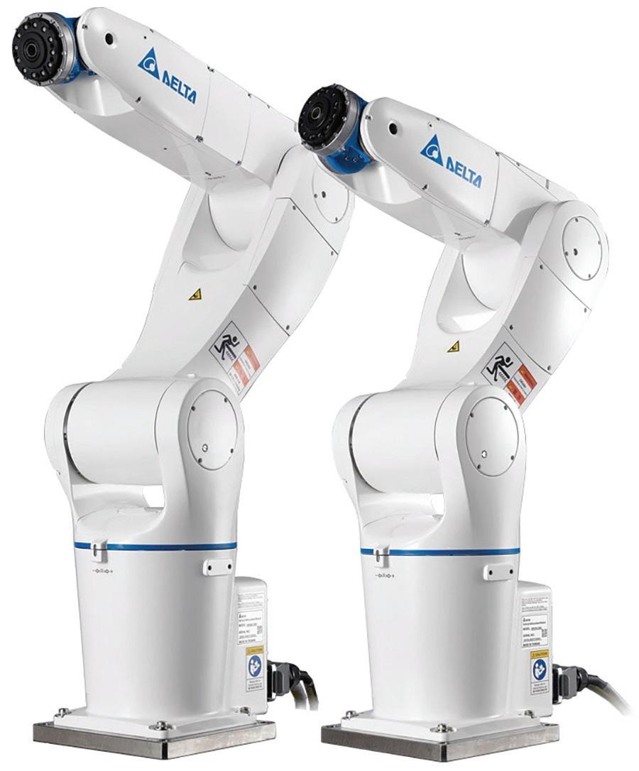
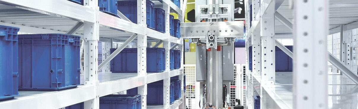
METAL LS, the Bulgarian manufacturer of door locking systems, door and window handles, and building hardware started planning the new automated assembly of door locks in 2019. The robotic systems the company already used for other applications were too large for the planned production site, so the new solutions needed to be as compact and precise as possible, in addition to being state of the art. Door and security locks are precision parts with standard dimensions and components stipulated in DIN standards. Therefore, quality and precision were critical deciding factors for METAL LS. The robots also needed to achieve high productivity — assembling between 10 and 14 locks per minute. Additionally, the company required a high level of fl exibility and the possibility of retooling to reuse the same system to produce new locks in the future. Following a comparison of various manufacturers and products, METAL LS opted for a robot system om Delta. It was the only manufacturer to off er a complete solution including programmable logic controllers (PLC), a human-machine interface (HMI), servo systems, and robotic arms with Machine Vision. To implement this project, METAL LS and Delta collaborated to develop a custom workstation for the assembly of the mechanical door lock components. The main part of the system comprises a rotation table on which seven, six-axis DRV90L7 articulated

robots are installed. The robots are capable of extremely precise, quick movements and have a hollow wrist that allows them to be easily combined with the correct tool for each production step. The DOP-115MX HMI is used to visualize all processes and enables the user to select various receipts for diff erent locks through a touch screen. It also displays system information and alerts or alarms. The AS300-series (AS324MT-A) PLC monitors the assembly line, controls the ASDA B2 servo drive, and communicates with the servo drive on the rotating platform. Two DMV2000 Machine Vision image processing systems equipped with cameras are installed to localize components on the conveyor and send accurate signals to the robot allowing it to pick up and assemble the parts. The AC servo system comprising ASDA-A2 and ASDA-B2 drives and ECMA motors ensure that the robot arms are positioned precisely and that high productivity can be maintained. A few adjustments to the parameter settings were su cient to quickly overcome initial communication problems between the PLC, robot, and the Machine Vision system. The careful preparation and system confi guration carried out by the Delta team also ensured that all the Delta industrial automation (IA) products were soon integrated into the production processes. Alongside the quality of the compact robotic system, METAL LS is pleased with the advice and customer service it has received. The project was kicked off when the Field Application Engineering (FAE) team arrived on-site to support the construction of the assembly system together with Mechatronics, Delta’s Bulgarian partner. The assembly system is still undergoing tests, but initial results are already showing improved productivity and performance. DW
Delta EMEA www.delta-emea.com
These six-axis DRV90L7 articulated robots are capable of extremely precise, quick movements and have a hollow wrist that allows them to be easily combined with the correct tool for each production step.

Interpower® Accessory Power Strips—Made in the U.S.A.!
Interpower Accessory Power Strips are efficient components of an accessory power system. Whether standalone or in tandem with a Power Distribution Unit, Accessory Power Strips can plug a countryspecific plug into the mains power. One IEC inlet and multiple IEC outlets along the strip allow multiple devices to be plugged in, keeping everything integrated in one unit. Customizable Interpower Accessory Power Strips current and voltages range from 10A-15A/100-240VAC. Choose from 2,4,6,8,10 or 20 sheet F outlets. The metal enclosures are powder coated for durability, and options include push button, rocker, or guarded circuit breakers, connector locks, and three colors (white, beige and black).
Toll-Free Phone: (800) 662-2290 E-mail: info@interpower.com
Business Hours:
7 a.m.–6 p.m. CST
Design Notes

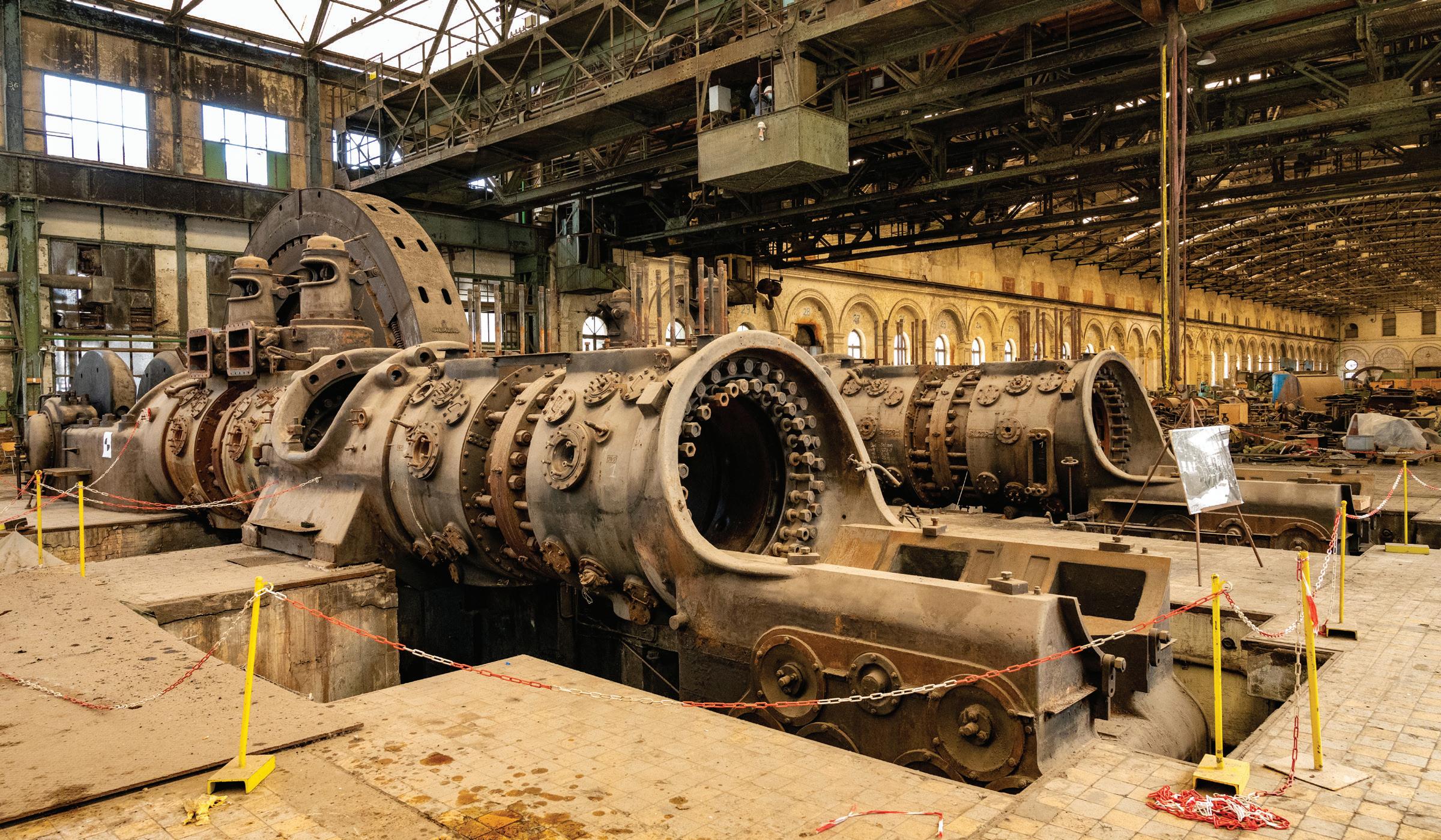
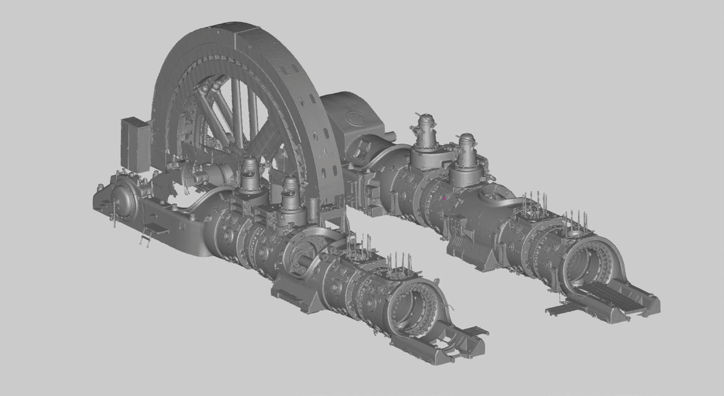
Built in 1938 by Ehrhardt & Sehmer, the Groussgasmaschinn is the largest gas engine ever built.
Edited by Mike Santora Managing Editor
Until recently, 3D scanners could only be used indoors, under certain lighting conditions, with a steady power source, and a powerful computer. They were o en bulky and heavy, making them hard to maneuver while scanning. Most signifi cantly, such scanners could only capture objects of limited sizes — something that could fi t on your desk. This was the situation the team at the Luxembourg Science Center found themselves in back in 2016 when they came up with a plan: to digitally preserve one of Luxembourg’s national monuments, the “Groussgasmaschinn” or Gas Engine №11 — the world’s largest blast furnace gas engine ever built. Built in 1938 by German manufacturing company Ehrhardt & Sehmer by order of a Franco-Belgian consortium called “Hautsfourneaux et Aciéries de Diff erdange, St-Ingbert & Rumelange” (HADIR), the Groussgasmaschinn is so large it could contain an entire tennis court, and then some. It is 26 meters long, 10.5 meters wide, 6.5 meters high, weighs 1,100 tons, and could produce 11,000 horsepower, or up to 7000 kilowatts. It has four cylinders, each of which had a capacity of 3,000 liters, and an 11-meter and 150-ton fl ywheel, which rotated at 94 RPM. The engine was operated by 12 workers per shi , and during its lifetime (1942-1979), produced more

than 6,000 kW of power om blast furnace gas (a waste product generated by the combustion of coke fuel in blast furnaces). Located in Diff erdange, Luxembourg’s industrial town 27 kilometers southwest of Luxembourg City, this 1,100-ton industrial masterpiece was one of 14 other gas machines of various sizes installed in the Diff erdange Gas Engine Plant between 1896 and the 1940s. A er its shutdown in 1979, the Groussgasmaschinn remained abandoned for nearly 30 years. It came back om the brink of oblivion in 2007 when Luxembourg’s Ministry of Culture designated it as a National Monument worthy of preservation and restoration. The restoration work began fi ve years later, in 2012. During this time, the Center developed the idea not simply to restore the gigantic engine to its best shape but also to digitally preserve it for future generations. In 2016, they reached out to Artec 3D in Luxembourg, but even the best of the scanning technology available at the time wasn’t able to capture something this huge. Fast forward a few years, and with new 3D scanning options available, Artec was ready to scan. “We’ve been meaning to scan this engine for a very long time, and we’re glad that the technology is fi nally here to help us do it. There is no other gas engine like this one, and it’s crucial to capture it in its current state,” said Nicolas Didier, President and General Manager of the Luxembourg Science Center. “It’s the largest object we ever scanned! And much bigger than I expected,” said Vadim Zaremba, Deployment and Technical Support Engineer at Artec 3D, when he fi rst visited the Gas Plant to assess the scope of future work in November 2020. A er examining the gas engine and passing all the required security procedures in early 2021, Vadim returned to the Gas Plant with his colleague, Technical Support Specialist Raul Monteiro, and all the necessary gear. As in most cases, the size and complexity of the object determines the scanners to be used. Artec Ray was chosen as the primary scanner for capturing the entire engine due to its ability to scan large objects om a distance with submillimeter accuracy, while the Artec Leo, a wireless, portable 3D scanner, was chosen as a second device, specifi cally for capturing high levels of detail om the smaller parts of the engine. The plan was to fi rst scan the engine with Ray om as many angles as possible, capture the entire object, and
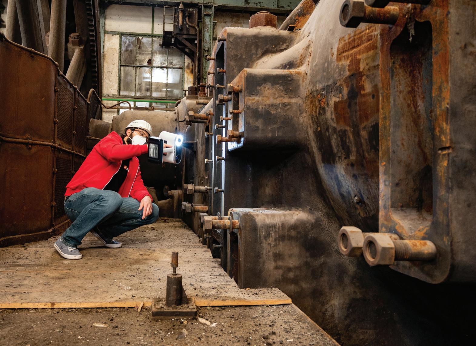
The size and complexity of the object determined the scanners to be used: Artec Ray and Artec Leo.
While the Ray silently scans the engine, Zaremba steps away for a minute or two of scanning smaller sections up close with Leo.
Design Notes

The fi nal polygonal 3D model of the Groussgasmaschinn.


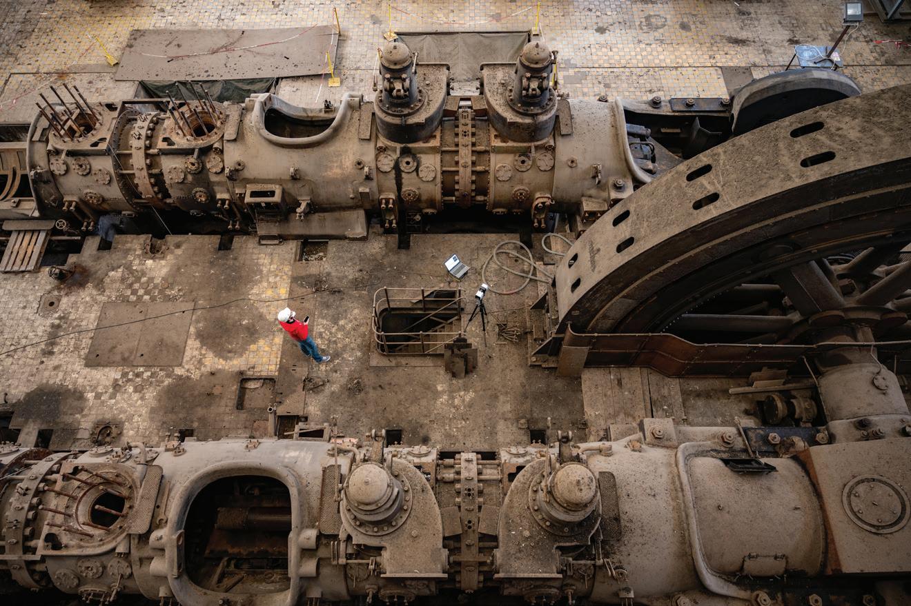
then go back and scan any missing, smaller, hard-to-reach sections with Leo. Because Ray was scanning at maximum resolution (point density), to save some time, the team decided to split up. Zaremba was positioning Ray at various locations, at one particular angle, 5 to 15 meters away om the engine, while Monteiro was scanning smaller sections of the engine (which weren’t in Ray’s fi eld of view) with Leo. Then Zaremba moved on to the next spot, and Monteiro followed behind, along the same route. One of the most challenging tasks was scanning the engine om above. To do this, the team had to climb a special bridge built in the 1940s-1950s, which features a cabin hanging 10 meters above the fl oor, as this was the ideal spot for scanning the engine om multiple angles. This was easier said than done. The bridge was old and unstable, and under the weight of two people plus a 3D scanner, such a foundation was not conducive to creating high-quality scans. To ensure that the scan data was fl awless, Zaremba and Monteiro had to remain completely still for several minutes while the scanner did its job. Overall, it took the team four working days to complete the project, with three to fourhour shi s of active scanning every day. The engine was scanned om 18 diff erent angles with Artec Ray, and these were later combined in Artec Studio with 67 more scans made with Artec Leo. The fi nal size of the project came to 186 GB in total, with 170 GB of Leo scans and 16 GB of Ray scans. Processing an object this big was a challenge in itself. To make sure all the data was processed correctly, Artec 3D Tech Support Engineer Dmitry Potoskuev split up the process into several batches:
● He started with Ray data fi rst. He cleaned up the data by removing all the unnecessary objects that the scanner picked up while scanning the engine (using the Eraser tool), such as parts of the Gas Plant building, windows, walls, and various other equipment around the GGM11.
● Then he focused on uni ing the fl ywheel and other parts data across all 18 scans by erasing specifi c data om some ames using
the Eraser tool. This was necessary because several scans were done on diff erent days, and the position of the fl ywheel and a few other parts changed a few times when the engine was turned on by GGM11 staff for demonstrations. This could result in some mismatches if those scans were merged as-is.

● A er that, all Ray scans went through Global Registration to be registered between each other. Then each of the 18 scans were processed into meshes using the “Ray scan triangulation” algorithm with Polygon edge length (max) at 10 mm. This was done to fi lter all the surfaces with a large distance between the vertices, and as a result, to get a more detailed and cleaner surface a erward. A er that, all the 18 triangulated meshes were processed using SharpFusion algorithm to create a single mesh aka “skeleton” of the engine’s model.

● The next step was to add all the details captured with Leo. Because of all the data (170 GB), Potoskuev broke the process down into several steps.

● First, he duplicated and locked the original Ray mesh. The duplicated copy was simplifi ed to 5-10 million polygons and locked too. This was done to further the registration process. Next, he uploaded all Leo scans (divided into 17 groups during scanning) to the duplicated Ray project, and each of them was registered with the separately simplifi ed Ray project for higherquality alignment of data.

● A er all the Leo scans were registered, Potoskuev selected the original Ray mesh and 4-5 raw registered Leo scans and applied the Sharp Fusion algorithm to create a new mesh. He repeated the process until all the Leo scans were processed with the original Ray mesh into a fi nal mesh of the gas engine.
The fi nal mesh consisted of around 350 million polygons, which were then reduced to 10 million polygons for further post-processing, using such features as Hole Filling tools, the Smooth Brush, and Bridges. The total processing time was all done within two weeks. “With this gigantic engine 3D scanned, we can use this data to restore some missing parts and preserve it in its current state, so even if it loses its shape with time, we can still go back to this 3D model and show it to our future visitors, and use it for restoration purposes,” said Nicolas Didier, President and General Manager of the Luxembourg Science Center. DW
Artec 3D | www.artec3d.com
EE Classroom on Silicon Carbide
Silicon Carbide (SiC) has made its mark in bringing faster, a smaller, and more reliable components than its fellow semiconductors to market. While SiC components have been around for a couple of decades, there is still a lot to learn and a lot to consider when choosing the most suitable WBG semiconductor for your device. LET US HELP with tutorials, from looking
at how WBG semis stack up in power conversion effi ciency to an overview of SiC FETs and MOSFETs.
Check out our EE Classroom to learn more:
www.eeworldonline.com/ silicon-carbide-classroom
POWER TRANSMISSION-PART CONVEYING PYRATHANE® BELTS
Lifetime Warranty Against Manufacturing Defects
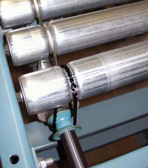
LINE SHAFT CONVEYOR BELTS
Original Equipment and Connectable CUSTOM MADE IN INCH, METRIC & O-RING SIZES • Round, Flat and Connectable Polyurethane Belts • Very Clean Operation • Eliminates Tensioning Devices • Exceptional Abrasion Resistancexxxxxxxxxxxxxx
AN ISO 9001 CERTIFIED COMPANY 641.792.2405 sales@pyramidbelts.com
Design Notes
How to streamline a microgrid system

Edited by Mike Santora • Managing Editor

Anyone hearing the term “microgrid” has their own
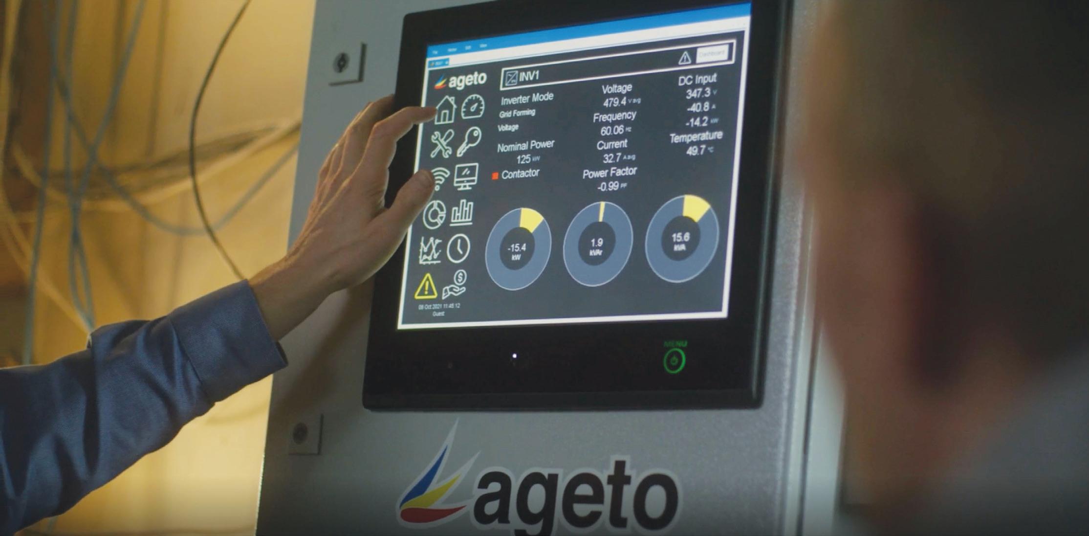
interpretation of what the word means. To the layperson, the defi nition may be as simple as knowing that it is smaller than a traditional-sized energy grid. They may understand that a microgrid is needed because a facility is located too far away om a main power grid to e ciently obtain the continuous energy required to power their systems. For those in the energy industry, when designing systems, the defi nition can be much more complex and aught with further questions. Some may ask why a microgrid is necessary at a particular location. Others might question what kind of energy is collected (solar or wind) and how it is being stored. Still, others may ask how this energy is being controlled and distributed. No matter the questions, engineers are looking for microgrids that provide stability, reliability, fl exibility, and e ciency for various locations and challenges. Companies such as Ageto Energy not only answer these questions but also off er additional value that people are looking for in microgrid solutions. With renewable energy, Ageto always comes back to one word, “simple.” Working toward its mission to accelerate the global adoption of renewable energy, it simplifi es the integration and control of off -grid, microgrid power systems. The company reduces complexity and integrates power systems for a future of growth with low-carbon emissions. One way they have done this is by coordinating all the elements of a microgrid and placing them into consolidated systems. Known as the Ageto ARC microgrid controller, this option allows users to monitor and manage energy resources to ensure everyone gets the power they need. The ARC microgrid controller has been defi ned as “the brain of your microgrid system, seamlessly integrating, optimizing, and managing diverse energy resources.” The interface makes it easy for the system operator to have full visibility of their system, energy resource health, and performance data. To deliver the reliable power they were looking for, especially in the case of off -grid systems, the Ageto team needed


Design Notes

to make sure that the individual components that made up the ARC controller system performed to direct specifi cations. “We have designed our controller to operate continuously for years with no downtime, and we look for products that can parallel that,” said Ageto COO Mike Murray. To do this, Ageto searched for specifi c parts that would make constructing their ARC controller as easy as it was to use. Initially he was looking for just terminal blocks, but Murray and his team found a company that provided the connectivity he needed and the programmable logic controllers (PLCs) the ARC controller required to bridge communication. WAGO, a company known for its CAGE CLAMP spring pressure technology and automation solutions, stepped in to provide Ageto the fl exibility and performance required for the project. The initial solution was a bridge between an existing battery storage system that used a Controller Area Network (CAN) communication protocol. However, the Ageto control system needed a Modbus TCP/IP input. The WAGO engineering team provided a
The WAGO engineering team provided a simple,


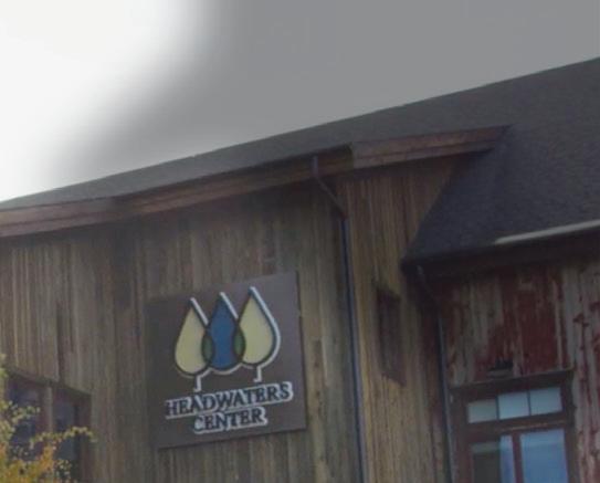
simple, scalable PLC with a CAN Master module and Modbus TCP port for communication with the ARC control panel. With this architecture, Ageto could monitor the battery requirements (voltage, charge, and temperature), and write a small routine for actual control of the battery storage system. This system acts as Ageto’s control interface into the storage system onsite. According to Jim Ratcliff e, Regional Sales Manager for WAGO, “The Ageto system is based on a model that allows them to be energy resource agnostic, off ering their customers multiple integration options across numerous existing onsite assets.” Knowing exactly what was required, a range of products could be tested by Ageto before deciding. “They were looking for a Controller Area Network (CAN) solution that they Ageto’s ARC microgrid controller can could install remotely in an be found in locations such as The
Headwaters Center in Winter Park,
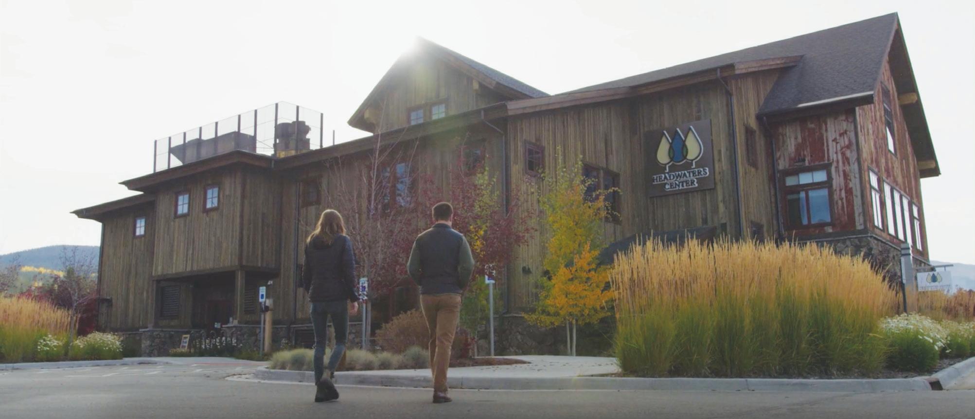
existing battery storage system, allowing them to communicate back to their own control platform,” said Ratcliff e. A er testing, Murray knew that WAGO was the company they wanted to go with. Ageto used terminal blocks, the CAN-based PLCs, and 221 wire-splicing connectors to customize their ARC microgrid controller. They also used these products in their Battery Management System (BMS) to help with temperature monitoring and load capacity challenges. Today, Ageto’s ARC microgrid controller can be found in locations such as The Headwaters Center in Winter Park, Colorado. Boasting Colorado’s fi rst off -the-grid gathering place, Headwaters hosts weddings, celebrations, concerts as well as educational opportunities. Most of the energy used in this Civil-War-era facility is solar energy. That energy is then stored and used om onsite batteries. Performing under the most demanding conditions, ARC microgrid controller provides Headwaters and other users the peace of mind knowing that they will get reliable, resilient energy om an independent source. The company’s unique interface, performance monitoring, and real-time controls make its microgrid solutions straightforward and easy to use. DW

WAGO wago.com
WHAT DO YOU THINK?
Connect and discuss this and other engineering design issues with thousands of professionals online

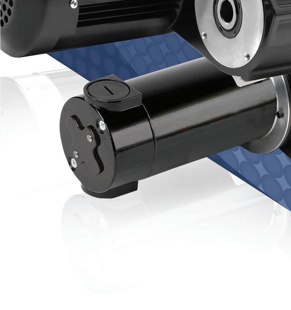
High-Torque High-Torque Hollow Shaft Hollow Shaft Gearmotors Gearmotors
Up to 1020 lb-in (115 Nm)
Our new AC and PMDC o set hollow shaft gearmotors simplify installation, reduce connection components and optimize mounting space. Ideal for conveyor systems, medical applications, food processing equipment and more. Available with stainless steel drive shaft kits.
Rated Speed 2-93 rpm
Rated Torque
≤ 1020 lb-in (up to 115 Nm)
Voltage
VDC VAC (3ph)
90, 180, 130, 12, 24 230/460 60 Hz
Gear Ratio
27:1 to 108:1


