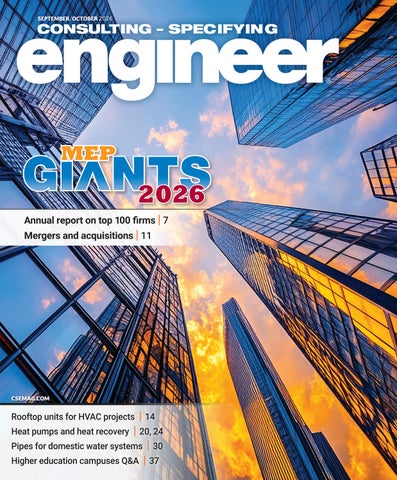
2026 2026 Annual report on top 100 firms | 7
Mergers and acquisitions | 11
CSEMAG.COM
Rooftop units for HVAC projects | 14
Heat pumps and heat recovery | 20, 24 Pipes for domestic water systems | 30 Higher education campuses Q&A | 37
CSE2609_MAG_COVER_V5msFINAL.indd 1
8/24/26 11:46 AM
www.csemag.com/ebooks
Arc Flash & Electrical Safety
Building Automation & Controls
Codes & Standards
Commissioning
Data Centers
Electrical & Power
EV Charging
Fire & Life Safety
Hospitals & Healthcare Facilities
HVAC/R
MEP Giants
Plumbing, Piping & Pumps
Smart Buildings
CSE House Ad_pg1.indd 1
The Future of HVAC is Predictive
6/16/26 10:33 AM
2026 2026 Annual report on top 100 firms | 7
Mergers and acquisitions | 11
CSEMAG.COM
Rooftop units for HVAC projects | 14
Heat pumps and heat recovery | 20, 24 Pipes for domestic water systems | 30 Higher education campuses Q&A | 37
CSE2609_MAG_COVER_V5msFINAL.indd 1
8/24/26 11:46 AM
The world’s most demanding data centers rely on power they can trust. Cummins combines proven reliability, scalable energy solutions, and decades of engineering expertise to help critical operations stay online, adapt to changing demands, and grow with confidence. Switch Confidence On with Cummins. And keep it on.
Scan the QR code to find out more about Cummins Power Systems solutions for data centers
Cummins_pgC2.indd 2
8/21/26 4:07 PM
The industry update you can walk through.
Co-Sponsored by
AHR_Intl Expo_pg01.indd 1
8/21/26 4:08 PM
What’s behind it is just as important as what’s inside it.
Introducing the all-new Fujitsu AIRSTAGE line of R-32 VRF systems… available now and backed by best-in-class training, service and support. Our R-32 VRF systems deliver the flexibility and high performance today’s projects demand, including capacities from 2 to 32 tons and a broad selection of indoor unit options. Combined with expert layout assistance, training, and responsive support, they’re designed to help you succeed from planning through installation and beyond. Confidence comes from knowing what’s behind it. Ready when you are.
GENERAL HVAC Solutions America, Inc.
Visit fujitsugeneral.com
© GENERAL HVAC Solutions America, Inc. - 2026 GHSA distributes Fujitsu and AIRSTAGE branded products made by its group companies. The Fujitsu trademark’s registered owner in the USA and Canada is Fujitsu Limited of Japan.
Fujitsu_pg02.indd 2 6872_FUJ_R-32 VRF Launch Ad_QR_Con Spec Engin_9x10.875_7.30.26_PUB .indd 1
8/21/26 4:09 PM 7/30/26 2:39 PM
Vol. 63 • No 5
Contents SEPTEMBER/OCTOBER 2026
7
NEWS&BUSINESS 5 | Success is what happens when succession planning takes place
Firms should prepare for junior team members to move into advanced positions via succession planning.
BUILDING SOLUTIONS 7 | 2026 MEP Giants numbers soar compared with last year
Total MEP design revenue increased, making this a lucrative year for the MEP Giants.
11 | More MEP Giants join the deal-making fray in 2025
A record share of firms got in on the acquisition action in 2025.
14 | Is an RTU the best option for your HVAC project?
RTUs rank higher than direct-expansion split systems or other HVAC systems.
ON THE COVER: Read about the 2026 Consulting-Specifying Engineer MEP Giants on page 7 and download full details at www.csemag.com/giants. Image courtesy: Adobe Stock
20 | How to improve efficiency and energy reuse with air-to-water heat pumps
p.14
Consolidating infrastructure and maximizing energy reuse are key benefits.
24 | Strategies for capturing more potential with heat recovery chiller design
Modular six-pipe heat recovery chillers help enable simultaneous heating and cooling.
p.24
30 | See how to properly size pipes for domestic water systems Following a few simple steps will lead to mastering this fundamental skill.
ENGINEERING INSIGHTS 37 | How to make higher education campuses future-ready
p.37
Engineers are helping colleges and universities modernize campus buildings with flexible designs.
CONSULTING-SPECIFYING ENGINEER ( Vol. 63, No. 5, ISSN 0892-5046, USPS PUBLICATION #901000 ) is published bimonthly by: Arrowfly; 1111 Superior Ave., Suite 1120, Cleveland, OH 44114. Periodicals postage paid at Cleveland, OH & additional mailing offices. POSTMASTER: Send address changes to CONSULTING-SPECIFYING ENGINEER, 1111 Superior Ave., Suite 1120, Cleveland, OH 44114. CONSULTING-SPECIFYING ENGINEER copyright 2026 by Arrowfly. All rights reserved. CONSULTING-SPECIFYING ENGINEER is a registered trademark of Arrowfly, used under license. Circulation records are maintained at Arrowfly, 1111 Superior Ave., Suite 1120, Cleveland, OH 44114. Telephone: 888-543-2447. Publications Mail Agreement No. 40685520. Return undeliverable Canadian addresses to: 1111 Superior Ave., Suite 1120, Cleveland, OH 44114. Rates for nonqualified subscriptions, including all issues: USA, $120/yr; Canada/Mexico, $150/yr (includes 7% GST, GST#123397457); International air delivery $260/yr. Except for special issues where price changes are indicated, single copies are available for $30 US and $35 foreign. Please address all subscription mail to CONSULTING-SPECIFYING ENGINEER, 1111 Superior Ave., Suite 1120, Cleveland, OH 44114. Printed in the USA. Arrowfly, does not assume and hereby disclaims any liability to any person for any loss or damage caused by errors or omissions in the material contained herein, regardless of whether such errors result from negligence, accident or any other cause whatsoever. CONSULTING SPECIFYING ENGINEER does not endorse any products, programs, or services of advertisers or editorial contributors. Copyright© 2026 by Arrowfly. No part of this publication may be reproduced in any form or by any means, electronic or mechanical, or by recording, or by any information storage or retrieval systems, without written permission from the publisher.
consulting-Specifying engineer— www.csemag.com
CSE2609_MAG_TOC_V3msFINAL.indd 3
September/October 2026
|3 8/24/26 11:50 AM
Altech_pg04.indd 4
8/21/26 4:09 PM
CONTENT
NEWS&BUSINESS
CONTENT SPECIALISTS/EDITORIAL
VIEWPOINT
AMARA ROZGUS, Editor-in-Chief ARozgus@Arrowfly.com FRANCES RICHARDS, Associate Editor FRichards@Arrowfly.com AMANDA PELLICCIONE, Marketing Research Manager APelliccione@Arrowfly.com MICHAEL SMITH, Art Director MSmith@Arrowfly.com
EDITORIAL ADVISORY BOARD DARREN BRUCE, PE, LEED AP BD+C, Director of Strategic Planning, Mid-Atlantic Region, NV5, Arlington, Va. MICHAEL CHOW, PE, CEM, CXA, LEED AP BD+C, Principal, Metro CD Engineering LLC, Columbus, Ohio CINDY COGIL, PE, FASHRAE, Vice President, SmithGroup, Chicago TOM DIVINE, PE, Senior Electrical Engineer, Johnston, LLC, Houston CORY DUGGIN, PE, LEED AP BD+C, BEMP, Energy Modeling Wizard, TLC Engineering Solutions, Brentwood, Tenn. PAUL ERICKSON, LEED AP BD+C Principal, Affiliated Engineers Inc., Madison, Wis. ROBERT J. GARRA JR., PE, CDT, Vice President, Electrical Engineer, CannonDesign, Grand Island, N.Y. JASON GERKE, PE, LEED AP BD+C, CXA, Senior Design Phase Manager, JP Cullen, Milwaukee JOSHUA D. GREENE, PE, Associate Principal, Simpson Gumpertz & Heger, Waltham, Mass. RAYMOND GRILL, PE, FSFPE, LEED AP, Principal, Ray Grill Consulting, PLLC, Clifton, Va. WILLIAM KOFFEL, PE, FSFPE, President, Koffel Associates Inc., Columbia, Md. WILLIAM KOSIK, PE, CEM, LEGACY LEED AP BD+C, Associate Principal, Sector Leader, HED, Chicago KENNETH KUTSMEDA, PE, LEED AP, Engineering Manager, Jacobs, Philadelphia DAVID LOWREY, Chief Fire Marshal, Boulder (Colo.) Fire Rescue JASON MAJERUS, PE, CEM, LEED AP, Principal, DLR Group, Cleveland CALEB MARVIN, PE, Senior Associate, Associate Partner, Certus Consulting Engineers, Dallas JUSTIN MILNE, PE, PMP, Senior Engineer, Southcentral Region, Jensen Hughes, Allen, Texas SPENCER PERRY, PE, Senior Vice President/Regional Team Leader, CDM Smith Inc., Maitland, Fla. CRAIG ROBERTS, CEM, Account Executive, National Technical Services, McKinstry, Powell, Tenn. SUNONDO ROY, PE, LEED AP, Director, Design Group, Oak Brook, Ill. JONATHAN SAJDAK, PE, Senior Associate/Fire Protection Engineer, Page, Houston RANDY SCHRECENGOST, PE, CEM, Austin Operations Group Manager/Senior Mechanical Engineer, Stanley Consultants, Austin, Texas MATT SHORT, PE, Project Manager/Mechanical Engineer, Smith Seckman Reid, Houston RICHARD VEDVIK, PE, Senior Electrical Engineer and Acoustics Engineer, IMEG Corp., Rock Island, Ill. TOBY WHITE, PE, LEED AP, Associate, Boston Fire & Life Safety Leader, Arup, Boston APRIL WOODS, PE, LEED AP BD+C, Vice President, WSP USA, Orlando, Fla. JOHN YOON, PE, LEED AP ID+C, Lead Electrical Engineer, McGuire Engineers Inc., Chicago
consulting-Specifying engineer — www.csemag.com
CSE2609_MAG_VIEW_V3msFINAL.indd 5
Success is what happens when succession planning takes place
A
Many consulting engineering firms fter 19 years with Consulthave been guided for years — someing-Specifying Engineer, this is times decades — by the same leadnot an easy column to write. er or small group of leaders. Their Serving as editor-in-chief of this knowledge is not limited to technipublication for 16 of those years has cal expertise. It includes clibeen one of the most excitent history, project judgment, ing positions I have held. I lessons learned, staff develhad the opportunity to work opment, manufacturer relawith industry experts who tionships and an instinct for are thoughtful, exacting and how the firm should respond deeply committed to doing when challenges arise. If that work that matters. Consultknowledge resides with only ing engineers do not simAmara Rozgus, one person, the firm is at ply design systems; they Editor-in-Chief risk. help create safer, more effiSuccession planning should not cient, more resilient buildings and be treated as an event that happens infrastructure. when someone announces retirement Over the years, this brand has or departure. It should be a continugrown and changed in ways that ous process. reflect the evolution of the industry Technical knowledge transfer also itself. We have launched education needs structure. Mentoring, project sessions and webcasts to help engidebriefs, internal training, documentneers stay current. We have developed ed design standards and cross-generawards programs to recognize excelational project teams all ensure that lence, innovation and leadership. We experience is not lost. have worked to strengthen the conRelationships require the same nection between our readers, contribcare. Clients need to know more than utors and industry partners. Through one person at the firm. Younger engiit all, the goal has remained the same: neers need opportunities to be seen, to provide high-quality, credible and heard and trusted. Longtime leaders technically sound content. must be willing to step back graduAs I move into a new position, I ally so others can move ahead with do so with deep appreciation for this confidence. audience and with confidence that Leaving a role after so many years the publication and its mission have reminds me that effective planning been thoughtfully passed on. That means caring enough about somekind of transition does not happen by thing to prepare it for the future. accident. It requires planning, trust That is true for a media brand, and it and a willingness to share what has is true for an engineering firm. cse been built. The same is true for engineering firms. September/October 2026
|5 8/24/26 11:51 AM
Powering the future of buildings. Designing safe, energy-efficient and resilient buildings.
The convergence of AI, electrification and the energy transition is transforming how buildings consume and manage energy. At the same time, owners and operators are under pressure to improve efficiency, meet sustainability goals and ensure uninterrupted performance. Our Buildings as a Grid approach empowers consulting and specifying engineers to design flexible, scalable power systems that integrate on-site generation, energy storage, electric vehicle charging and microgrids. The result is resilient, future-ready infrastructure that lowers operating costs, accelerates decarbonization and evolves with changing standards, technologies and business needs. Eaton.com/Buildings
Eaton_pg06.indd 6
8/21/26 4:10 PM
2026 S P E C I A L R E P O R T 2026
2026 MEP Giants numbers soar compared with last year Total MEP design revenue increased, making this
a lucrative year for the MEP Giants.
T
he 2026 Consulting-Specifying Engineer MEP Giants, which represents data collected from the 2025 fiscal year, show a larger and more revenue-heavy market than the previous year’s data. Across the mechanical, electrical, plumbing (MEP) and fire protection engineering firms highlighted, total gross revenue rose from about $73.79 billion in 2024 to $98 billion in 2025, while total MEP design revenue increased from $15.02 billion to $19.18 billion, representing an increase of 27.7%. The average percentage of revenue attributed to MEP work also edged up,
from 55.7% to 56.9%, suggesting that the listed firms remain highly concentrated in building systems work even as several multidisciplinary firms continue to dominate the top of the ranking. At the top of the list, Jacobs retained the No. 1 position, followed again by Burns & McDonnell at No. 2. The most notable additions near the top are Harris, which entered the list at No. 3, and AECOM, which appears at No. 5. WSP moved from No. 3 to No. 4, while Mott MacDonald slipped from No. 4 to No. 6. Salas O’Brien held steady at No. 7, and Stantec remained No. 8. HDR moved from No. 6 to No. 9, while EXP remained No. 10.
‘
Across the MEP and fire protection engineering firms highlighted, total gross revenue rose.
’
Table 1 shows the top firms based on MEP design revenue, which is how the MEP Giants are ranked.
slight increase from last year. Courtesy: Consulting-Specifying Engineer
Shifting MEP Giants firms There were 20 firms appearing in the current data that were not exact matches the previous year. These include Harris; AECOM; Alfa Tech Consulting Engineers; Jaros, Baum & Bolles (JB&B); Coffman Engineers; Fishbeck; GFT; HEAPY Engineering; STV; Resolut; EMA Engineering and Consulting; ENFRA; Hipp Design + Consulting; Precis Engineering + Architecture; BSA; BRPH Companies; Michaud Cooley Erickson (MCE); Bowman Consulting Group; DFW Consulting Group; and Jacob Feinberg Katz & Michaeli Consulting Group. Some of these appear to reflect naming changes or rebranding rather than purely new market entrants, such as Alfa Tech/Vela Tech - AlfaTech, GFT/Gannett Fleming TranSystems, JB&B, EMA and Michaud Cooley Erickson.
consulting-Specifying engineer— www.csemag.com
September/October 2026
Top 10 firms by MEP design revenue Rank
Firm
MEP design revenue
1
Jacobs
$2,398,000,000
2
Burns & McDonnell
$2,137,909,556
3
Harris
$1,760,868,589
4
WSP
$1,503,911,733
5
AECOM
$145,256,4000
6
Mott MacDonald
$813,285,914
7
Salas O’Brien
$614,048,509
8
Stantec
$601,387,857
9
HDR
$537,246,534
10
EXP
$481,085,000
TABLE 1: Top 10 firms are listed by MEP design revenue; these 10 firms earned $1.23 billion out of $19.18 billion earned by all 2026 Consulting-Specifying Engineer MEP Giants. Jacobs topped the list yet again — as it has since 2013 — with $2.39 billion in MEP design revenue, a
CSE2609_MAG_MEPGIANTS_V3msFINAL.indd 7
|7 8/24/26 11:52 AM
2026 S P E C I A L R E P O R T 2026
‘
Portions of the
MEP design billings Commissioning (at any level) Building automation/ controls Lighting Fire/life safety/ security
list are becoming
Other
either more specialized
HVAC
5%
5%
6%
4%
in MEP/FP services
32%
or more diversified
7%
across other 13%
disciplines.
29%
Plumbing
Insights
Electrical/power
u
csemag.com
FIGURE 1: The top two areas in which 2026 Consulting-Specifying Engineer MEP Giants earned revenue — HVAC and electrical/power projects — varies very little year over year.
MEP Giants insights
Courtesy: Consulting-Specifying Engineer
Ranking movement was substantial among several firms. The largest positive jumps were LaBella Associates, up 27 spots from No. 62 to No. 35, and Arora Engineers, up 26 spots from No. 73 to No. 47. Other significant gains included Johnson, Mirmiran & Thompson and DLB Associates Consulting Engineers, each up 14 spots; Power Design, up 10; and McKim & Creed, up six. The largest declines included ThermalTech Engineering, down 33 spots from No. 44 to No. 77; Pond & Co., down 18; Ghafari Associates, down 13; EwingCole, down nine; Smith Seckman Reid, down seven; and LiRo Engineers, down six. Several year-over-year percentage shifts point to broader changes in firm revenue mix rather than simple ranking movement. The data suggests that some firms are reporting a larger share of MEP revenue from U.S.-based projects, while others show a greater concentration of work outside the U.S. or a different geographic balance than in the previous year. Similarly, changes in the percentage of total revenue attributed to MEP
8 | September/October 2026 CSE2609_MAG_MEPGIANTS_V3msFINAL.indd 8
’
u The 2026 MEP Giants reported a significantly
work indicate that portions of the list are becoming either more specialized in MEP/FP services or more diversified across other disciplines. These shifts may reflect changes in project mix, market focus, acquisitions, organizational restructuring or reporting methodology. Overall, the 2026 Consulting-Specifying Engineer MEP Giants reflect a stronger revenue base, continued dominance by large national and global firms, and meaningful volatility among midranked firms. For consulting engineers and MEP/FP industry observers, the data points to both consolidation at the top and competitive movement throughout the ranking. It also suggests that the market is not changing only in size, but also in composition, with firms adjusting geographically, strategically and operationally as demand for MEP/FP design services continues to evolve. cse Amara Rozgus, Editor-in-Chief, and Amanda Pelliccione, Marketing Research Manager, Consulting-Specifying Engineer
larger market, with total gross revenue rising to $98 billion and MEP design revenue climbing 27.7%, reflecting continued demand for building systems expertise across a shifting mix of firms and project types.
u The MEP Giants also showed notable growth in
staffing, sustainability work and public-company participation, while ranking movement and revenue-mix changes point to an industry that is expanding, consolidating and evolving beyond traditional MEP/FP design boundaries.
Online
u
csemag.com
Read the full 2026 Consulting-Specifying Engineer MEP Giants report at www.csemag.com/giants.
consulting-Specifying engineer — www.csemag.com
8/24/26 11:52 AM
Belimo RetroFIT+
Enhanced Carbon Reduction, Comfort, and Safety Through Building Retrofits HVAC retrofits create opportunities to boost comfort, improve indoor air quality, and reduce energy use. With decades of expertise and a proven portfolio of high-performance solutions, Belimo is a trusted partner—whether you need quick wins, intelligent upgrades, or full-system modernization. Our solutions deliver consistent, scalable results across your entire building portfolio. Through reliable products, expert support, and collaborative partnerships, Belimo helps reduce carbon footprints, meet environmental and economic goals, and elevate occupant comfort. With both standard and custom retrofit options, we ensure you get the right solution for long-lasting impact.
Discover the opportunities
www.belimo.com
Belimo_pg09.indd 9
8/21/26 4:11 PM
Complete Air Solutions. One Brand. Engineered for performance across the entire building.
Greenheck delivers the industry’s most complete selection of air movement, control, and conditioning products. From fans, dampers, louvers and make-up air units to energy recovery and packaged rooftop units, our solutions support safer, healthier, and more energy-efficient buildings. Explore the complete offering at greenheck.com.
Scan the QR code to find your rep.
© 2026 Greenheck
Greenheck_pg10.indd 10
8/21/26 4:12 PM
2026 S P E C I A L R E P O R T 2026
More MEP Giants join the deal-making fray in 2025 Total deal volume by the 2026 MEP Giants eased last year, but a record share of firms got in on the acquisition action.
R
ather than tapping the brakes in the face of global geopolitical turmoil and economic uncertainty, Consulting-Specifying Engineer’s 2026 MEP Giants continued a strong pace of deal-making last year, even as total activity eased from 2024’s blistering pace. As a group, the largest mechanical, electrical, plumbing (MEP) and fire protection engineering firms completed 64 acquisitions in 2025 — a 7% decline from the previous year’s near-record total of 69, though still one of the most active years for the group over the past decade. The percentage of MEP Giants making at least one acquisition climbed from 21% in 2024 to 30% in 2025 — the highest ever
Number of deals made by MEP Giants 70
69
65
64
2022
2023 Year
Global, U.S. M&A activity climbs to new highs The deal-making surge among the MEP Giants mirrors the broader M&A boom among AE and environmental firms that’s been driven on the supply side by a wave of baby boomers and Gen-X sellers seeking capital to support growth and facilitate
Percent of MEP Giants reporting a deal 29
54
2021
ties in critical sectors like energy efficiency, healthcare and pharmaceuticals and especially data centers. With MEP firms in high demand over the past year, it’s no surprise that the MEP Giants aggressively pursued acquisitions to add specialties to their service lines while sellers looked to capitalize on favorable valuations.
share recorded. Further, 15 MEP Giants closed more than one acquisition last year, up from 12 in 2024, even as the average number of deals per active buyer eased from 2024’s elevated pace. MEP firms of all types are prime acquisition targets. According to Morrissey Goodale’s propriety database of architecture, engineering (AE) and environmental industry deals, MEP firms are commanding median valuations around seven times annual EBITDA (earnings before interest, taxes, depreciation and amortization) compared to median valuations in the range of six times annual EBITDA for engineering firms overall. The edge in valuations for MEP firms likely reflects the higher demand for firms with niche special-
30 26
25 21
2024
2025
2021
2022
2023 Year
2024
2025
FIGURE 1: The number of deals made by the 2026 MEP Giants firms
FIGURE 2: In 2025, 30% of the MEP Giants reported a transaction,
eased in 2025 from 2024’s near-record pace but remained among
the highest percentage on record. Courtesy: Morrissey Goodale
the group’s most active years. Courtesy: Morrissey Goodale
consulting-Specifying engineer— www.csemag.com
CSE2609_MAG_MEPGIANTS_MA_V5msFINAL.indd 11
September/October 2026
| 11 8/24/26 11:53 AM
2026 S P E C I A L R E P O R T 2026 ownership transitions and on the demand side by strategic buyers and investors hungry for growth, talent and superior returns on investment. Morrissey Goodale tracked 805 global industry deals in 2025 — a new record that eclipsed the previous high of 770 worldwide acquisitions in 2024 and represented a 5% increase over the previous year. In the U.S., 512 transactions were concluded in 2025, surpassing the prior all-time domestic peak of 497 deals set in 2022 and up 6% from 485 in 2024.
‘
Private equity-backed
buyers accounted for just 22% of deals consummated by the MEP Giants in 2025.
’
As with the wider AE and environmental industry, Sun Belt firms continue to be among the most attractive M&A targets for MEP Giants. With five, four and four deals, respectively, California, Florida and North Carolina were the top states where MEP Giants completed acquisitions in 2025. That was followed by Ohio, South Carolina, New York, Texas and Massachusetts with three each. MEP Giants also concluded 11 international deals, with three purchases in the United Kingdom, two each in New Zealand, Ireland and Canada and one each in Australia and Norway.
Private equity pulls back among MEP Giants The MEP Giants continue to differ from the broader AE and environmental industry in the mix of buyer types pursuing acquisitions. Employee-owned buyers closed 43% of U.S. domestic AE and environmental industry transactions in 2025 and represented 45% of deals completed by the MEP Giants last year. By comparison, publicly traded buyers represented just 9% of overall industry transactions but accounted for 33%
12 | September/October 2026 CSE2609_MAG_MEPGIANTS_MA_V5msFINAL.indd 12
of MEP Giants deals in 2025. Private equity-backed buyers accounted for just 22% of deals consummated by the MEP Giants in 2025. That was down from 29% in 2024 and well below the 47% of acquisitions attributed to them across the entire industry last year.
M&A activity in the AE and environmental industry set records again in 2025 and Morrissey Goodale expects deal-making to remain a defining feature of the industry in 2026. Buyers remain focused on securing expertise in public infrastructure and mission critical markets, while sellers are motivated by attractive valuations and opportunities to join larger platforms with deeper and better corporate resources. These dynamics continue to fuel deal-making, particularly in high-growth markets such as California, Florida, Texas and the Southeast. Whether the MEP Giants return to a faster pace of acquisitions or continue spreading deal activity across a broader set of buyers, as they did in 2025, will be one of the storylines to watch this year. cse
Salas O’Brien most active buyer among MEP Giants Acquisitions have long been a key growth strategy for Salas O’Brien (Irvine, California), the 2023 recipient of Morrissey Goodale’s Best M&A Post-Transaction Performance Award. Last year, the private equity-backed engineering and design firm led all MEP Giants in deal activity, completing 10 acquisitions that added more than 430 employees across nine states and Canada. Additional MEP Giants tied for the second-most acquisitions in 2025 with Peter Frank is a Research Manager with five apiece were NV5 Global (Hollywood, Morrissey Goodale LLC, a specialized manFlorida); IMEG (Rock Island, Illinois), agement consulting and research firm excluthe 2023 recipient of Morrissey Goodale’s sively serving the architecture, engineering Most Prolific and Proficient Acquirer and environmental consulting industries. Award; and Bowman Consulting Group u (Reston, Virginia). csemag.com Other MEP Giants that completed multiple acquisitions in 2025 included WSP Merger and acquisition (M&A) insights (Montreal), Stantec (Edmonton, Canau While the number of 2025 MEP Giants making deals dipped last year, big buyers ramped up da), LaBella Associates (Rochester, New activity and drove total acquisitions to a nearYork), CannonDesign (Buffalo, New York), record level. Tetra Tech (Pasadena, California), McKim u Sun Belt firms continue to be the most & Creed (Raleigh, North Carolina), Jenattractive M&A targets for MEP Giants. sen Hughes (Columbia, Maryland), HDR (Omaha, Nebraska), DLR Group (Seattle), AECOM (Dallas) and Harris Company (St. Paul, Minnesota). Despite ongoing economic uncertainty driven by geopolitical events abroad and adoption of artificial intelligence in 2026, MEP firms are looking at another year of solid revenue growth and profitability driven by sustained demand. With many CEOs reporting confidence in the year ahead, firms are capitalizing on the opportunities u csemag.com at hand by continuing to invest in acquisitions as a critical component of strategic Read the full 2026 Consulting-Specifying Engineer MEP Giants report at www.csemag.com/giants. expansion.
Insights
Online
consulting-Specifying engineer — www.csemag.com
8/24/26 11:53 AM
IEM_pg13.indd 13
8/21/26 4:13 PM
BUILDING SOLUTIONS HVAC/R AND MECHANICAL
Caley Johnson and Alexandria Stuart, PE, CDM Smith, Maitland, Florida
Is an RTU the best option for your HVAC project? RTUs rank higher than traditional direct expansion split systems or other HVAC systems because of their simple, all in one packaging, energy benefits and space-saving nature.
P
ackaged rooftop units (RTU) are factory-assembled packaged heating and cooling systems that are installed on the roof of a building. The units condition air and distribute it throughout a building’s airspace via ductwork installed within the building. Unlike traditional split system heating, ventilation and air conditioning (HVAC) units, packaged RTUs combine all heating and cooling components into a single enclosure. These components include compressors, condenser and evaporator coils, supply and return fans, heating modules, fil-
FIGURE 1: Unitary packaged rooftop unit with an outdoor air intake hood. Courtesy: CDM Smith
14 | September/October 2026 CSE2609_MAG_RTU_V3ms_FINAL.indd 14
ters, dampers and control systems. The capacity of RTUs ranges from 2 to 150 tons. Small, light commercial capacity RTUs fall in the 2 to 15 tons range. Medium commercial RTUs range from 15 to 25 tons. RTUs 25 tons and larger are considered heavy commercial/industrial. Over the past few decades, RTU technology has evolved considerably. RTUs were once basic constant-volume systems and have become more sophisticated, containing advanced controls and components that provide more flexibility for building HVAC.
Packaged RTU configurations Packaged RTUs have a broad range of configurations available for different building requirements. RTUs can meet varying occupancy loads, ventilation demands, climate conditions and energy efficiency requirements. While most standard rooftop HVAC units include the same components as split system units in a single package, RTUs can also be provided in different configurations to meet specific design needs. These configurations include 100% dedicated outside air systems (DOAS), heat pumps, cooling only, variable air volume (VAV) or constant volume. RTUs can also be provided with electric or gas power inputs, providing versatility for different sites and the utilities that are available. To ensure the appropriate configuration is used for the specific application, it is essential to understand the different types of RTUs that are available. Constant-volume RTUs: Constant-volume RTUs are the simplest and most widely used configurations. In this configuration, the supply fan provides a fixed airflow rate whenever the system is operating. Constant-volume RTUs are typically used in smaller commercial buildings where building loads typically remain consistent throughout operating hours. Constant-volume RTUs have relconsulting-Specifying engineer — www.csemag.com
8/24/26 2:13 PM
atively easy installation, simplified controls and lower maintenance requirements. Variable air volume (VAV) RTUs: These vary the amount of supply air delivered to different zones based on thermal demand. In a VAV system, the VAV RTU supplies conditioned air to multiple terminal boxes located in different zones throughout the building. These terminal boxes regulate airflow to each zone or space according to temperature requirements. VAV RTUs are often used in office buildings and in educational facilities where occupancy and thermal loads vary throughout the day. VAV RTUs are generally more energy efficient than constant-volume systems and can provide more precise occupant comfort. DOAS: A DOAS RTU provides conditioned outdoor ventilation air to a space. DOASs are typically used in buildings that have high outdoor ventilation air requirements, such as schools, healthcare facilities, office buildings and laboratories. A DOAS provides the ability to separate ventilation air and thermal conditioning.
Packaged RTU components Packaged RTUs all include the same components as a typical direct expansion (DX) split system packaged into a single enclosure. However, RTUs can be provided with additional accessories in a much simpler manner than that required for a split system with the same components. Economizers: One of the most common RTU accessories is the air-side economizer. In many jurisdictions, the energy code requires an economizer to be installed to provide cooling when outside air conditions are cool enough. When outside air conditions are suitable, the economizer uses the outside air for free cooling, shutting down the refrigeration cycle. This results in significant energy savings and reduces wear and tear on the system. Packaged RTUs can easily be provided with an economizer option built into the unit. A split system that requires an economizer would result in installing motorized dampers on the return air mixing box, allowing the system to pull in outside air. Providing a split system with an economizer also requires additional controls and wiring to properly function. With a packaged RTU, providing an economizer and the associated controls to meet code is much easier to achieve than with other types of HVAC systems as the economizer is factory installed with the packaged system. consulting-Specifying engineer— www.csemag.com
CSE2609_MAG_RTU_V3ms_FINAL.indd 15
FIGURE 2: Tollbooth with a unitary packaged rooftop unit. Courtesy: CDM Smith
‘
RTUs can meet varying occupancy loads, ventilation demands, climate conditions and energy efficiency requirements.
’
Outdoor air intake hood: ASHRAE Standard 62.1: Ventilation for Acceptable Indoor Air Quality dictates the amount of fresh outdoor air that must be supplied to a space based on occupancy type. In a DX split system design, outdoor air is introduced into the indoor air handling unit via intake louvers and associated ductwork. This means additional u space and openings must be accounted for. Alternatively, for a packaged RTU, outdoor air • Learn what a packaged is simply introduced into the system by an outdoor rooftop unit (RTU) is, including its components air intake hood accessory added onto the unit. This and configurations. eliminates the need for additional ductwork and • Understand the energy wall space for an outdoor air intake louver, making codes related to RTUs providing outdoor air into the HVAC system much and how energy codes favor RTUs because of simpler. In Figure 1, the outdoor air intake hood is economizers. indicated by the arrow. • Review the benefits and Energy recovery ventilator: Packaged RTUs can limitations of packaged be provided with energy recovery ventilators for RTUs.
Learning
Objectives
September/October 2026
| 15 8/24/26 2:13 PM
BUILDING SOLUTIONS HVAC/R AND MECHANICAL
FIGURE 3: Packaged rooftop unit with condensate piping. Courtesy: CDM Smith
applications with high ventilation loads. The energy recovery ventilator transfers air from the exhaust airstream into the outdoor airstream. Energy recovery ventilators also assist in reducing the cooling and heating loads for the HVAC system. Some packaged RTU system manufacturers can factory install energy recovery ventilators directly into the unit. Hot gas reheat: Humidity control in buildings is an important aspect in providing occupant comfort. Humidity control is also essential in maintaining quality in specific applications such as sensitive medical procedures. Packaged RTUs can be factory provided with a hot gas reheat coil downstream of the evaporator, allowing the unit to dehumidify the supply air without using new energy. Packaged RTUs with hot gas reheat coils installed provide the system with operational flexibility and enhanced humidity control. Exhaust system: Packaged RTUs can be ordered with a factory-installed exhaust fan. The exhaust fan assembly helps maintain proper building pressurization. A packaged RTU with a factory-installed exhaust fan reduces the need for additional equipment and controls. Powered exhaust systems with dedicated fans are a common solution; however, a barometric relief damper can also be used to relieve excess air when the building becomes over-pressurized. Controls: Controls for a packaged RTU are factory installed and integral to the unit itself. This allows for factory testing and installation ease. However, some owners opt to only have the minimum factory controls and integrate the RTU into their own control system. Heating systems: Heat pump RTUs provide both heating and cooling using the refrigeration cycle. In cooling mode, the heat pump operates like a conventional air conditioner. In heating mode, the refrigeration cycle reverses. This allows the out-
16 | September/October 2026 CSE2609_MAG_RTU_V3ms_FINAL.indd 16
door coil to absorb heat and transfer it indoors. Other options for heating include auxiliary electric heating coils, natural gas heating and other fossil fuel heating sources.
Codes and standards governing RTUs Multiple codes and standards pertain to packaged RTUs; key codes and standards are listed. Generally, these codes can be categorized as related to unit construction, building codes and other considerations. Unit construction: • NFPA 70: National Electrical Code: Electrical components, devices and accessories will be listed and labeled, as defined in NFPA 70, by a nationally recognized testing laboratory and marked for the intended location and application. • NFPA 90A: Standard for the Installation of Air-Conditioning and Ventilating Systems: The design, fabrication and installation of RTUs and components will comply with NFPA 90A. • ASHRAE Standard 15: Safety Standard for Refrigeration Systems: RTUs must comply with ASHRAE 15 for refrigeration system safety.w • ASHRAE Standard 90.1: Energy Standard for Buildings Except Low-Rise Residential Buildings: The energy efficiency of HVAC units, including RTUs, is governed by ASHRAE 90.1. Building code: • International Building Code (IBC): Either the IBC or the local jurisdiction equivalent covers structural support, rooftop loading, wind resistance, seismic restraint, fire ratings, equipment anchorage and roof penetrations. • International Mechanical Code (IMC): Either the IMC or the local jurisdiction equivalent covers HVAC system installation, ventilation, equipment access, combustion air, exhaust systems, rooftop clearances and condensate disposal. • International Energy Conservation Code (IECC): Either the IECC or the local jurisdiction equivalent covers HVAC efficiency, economizer requirements, insulation, controls, commissioning and energy performance standards. Additional considerations: • SMACNA HVAC Duct Construction Standards: The industry standard for duct gauge consulting-Specifying engineer — www.csemag.com
8/24/26 2:13 PM
‘
During design,
thickness, reinforcement spacing, flange construction, transverse joints, leakage classes, exterior duct construction, support spacing and weatherproofing. • ASCE 7: Minimum Design Loads and Associated Criteria for Buildings and Other Structures: The standard for wind loads on rooftop equipment, seismic restraint requirements, equipment anchorage, curb attachment forces, exterior ductwork support requirements. This standard affects RTU anchorage details, supports and wind restraint cables/bracing. • Occupational Safety and Health Administration: Walking-Working Surfaces Standards: This standard applies to rooftop access, fall protection, ladders, guardrails and maintenance pathways. • Manufacturer required clearances: Manufacturers publish their required clearances for a unit’s maintenance, service, repair and for adequate airflow for proper operation.
Benefits of packaged RTUs Space efficiency: One of the primary advantages of packaged RTUs is space efficiency. Packaged RTUs eliminate the need for the indoor floor space that is typically required for split systems, which have both an indoor and outdoor unit. Leveraging a packaged RTU can even eliminate the space needed for mechanical rooms or equipment closets. Noise efficiency: Implementing a packaged RTU allows for any unit noise to be at the exterior of the building. This can be beneficial especially for noise-critical structures where sound levels inside the building may be sensitive. Lightweight roof structures, short ducts runs and lack of insulation at roof curbs can increase noise within the occupied area, but proper detailing can mitigate these concerns. Piping efficiency: Because of the configuration of packaged RTU systems, all the refrigerant piping is internal to the unit, whereas split systems require refrigerant piping to be routed from the internal unit to the external unit. Packaged RTUs allow for fewer building penetrations, less complex pipe routing and reduced construction coordination. RTU factory-installed and tested piping systems reduce the risk of improper refrigerant pipe instalconsulting-Specifying engineer— www.csemag.com
CSE2609_MAG_RTU_V3ms_FINAL.indd 17
lation (e.g., poorly brazed and flared joints, lack of engineers must pressure testing, failure to purge and evacuate pipdetermine the ing, missing insulation, missing filters dryers and site glasses, improper oil traps and incorrect pipe appropriate sizes). Energy efficiency: Most packaged RTU mancorrosion-resisufacturers tout that their units are more energy tant coatings efficient because of variable speed fans, energy recovery systems, smart building controls, and specialized high-efficiency compressors and economizers. However, the economizer function, which is materials to proan IECC requirement (with a few exceptions) mote equipment is much more likely to be used and provide free cooling to a building than any other unit type longevity. because of the simplistic controls required to activate it. When compared to DX split systems, each RTU model is a complete system and does not require finding the efficiency of a particular indoor unit and outdoor unit combination. RTUs have options for integrated economizers. Some RTUs include energy-efficiency upgrades such as multispeed or fully variable indoor fan controls, integrated energy recovery ventilation and staged or modulating heating and cooling capacities that are not typical on traditional DX split systems. Ease of maintenance: Maintaining a packaged RTU allows for some unique benefits. Being located on the roof, unit service can usually occur without disrupting building occupants. Additionally, being on the roof usually permits greater service clearances as the RTU mechanic does not have to try and squeeze the unit into a small u csemag.com mechanical room or equipment closet. A single packaged unit from a single manufacturer proRTU insights vides factory-coordinated components and quicku Packaged RTU systems er troubleshooting. offer a space-efficient solution by combining Scalability: Buildings can be designed with all heating and cooling multiple RTUs serving different areas. This scalcomponents into a single ability provides flexibility and reliability. If one rooftop enclosure. u Modern RTU technology unit stops working, the remaining units can conprovides significant tinue to condition other building zones.
’
Insights
Packaged RTU applications Scenarios in which these types of units are the most beneficial are space types that have limited physical space, are multitenant, are likely to undergo renovations or have high-airflow requirements. Some examples include:
versatility through various configurations like VAV and DOAS, as well as factoryinstalled accessories such as economizers that enhance energy efficiency and simplify maintenance and installation.
September/October 2026
| 17 8/24/26 2:13 PM
BUILDING SOLUTIONS HVAC/R AND MECHANICAL
• Gun stores • Office buildings • Supermarkets • Restaurants • Retail spaces • Tollbooths • Warehouses In Figure 2, a packaged roof top unit is provided to condition a tollbooth.
Limitations of packaged RTUs While packaged RTUs provide many benefits, they also have limitations. A key design consideration for packaged RTUs is the structural effect on the roof. Therefore, during design, engineers must verify the roof can safely support the large equipment weight and they must account for wind load, seismic load and vibration isolation. Another major concern is weather exposure. Rooftop systems are exposed
to all types of weather year-round. Environmental exposure can cause corrosion and wear on the equipment. During design, engineers must determine the appropriate corrosion-resistant coatings and specialized materials to promote equipment longevity. Although noise was mentioned above as a benefit, it can also be a concern for owners. In places where there are exterior noise restrictions, like in a neighborhood, keeping some equipment internal to a building may be a better alternative. Careful attention also needs to be paid to sealing penetrations and making sure the building envelope is weathertight. If the roofing system is installed poorly, roofing and moisture problems can occur. Last, when it comes to energy efficiency, the 2024 IECC has the same minimum efficiency requirements for air-cooled air conditioners regardless of
whether they are single packaged systems or a split system. Although packaged RTUs reduce the need for refrigerant pipe routing, condensate discharge pipe routing must be accounted for. In Figure 3, the condensate piping is shown to run along the roof and is sustaining plant life. A concern for maintenance is that these units are out of sight and out of mind, so the systems and surrounds can become neglected without a careful maintenance plan. cse Caley Johnson is a mechanical engineer at CDM Smith, focusing on HVAC and plumbing system design for wastewater and water treatment plants. Alexandria Stuart, PE, is a mechanical engineer at CDM Smith, focusing on HVAC and plumbing system design for wastewater and water treatment plants.
26_008059_Consulting_Specifying_Engineer_SEP Mod: June 25, 2026 2:36 PM Print: 07/21/26 page 1 v2.5
π SHIPPING SUPPLY SPECIALISTS
BEST QUALITY AND SELECTION IN NORTH AMERICA
ORDER BY 6 PM FOR SAME DAY SHIPPING
1-800-295-5510
CSE2609_MAG_RTU_V3ms_FINAL.indd 18
uline.com
8/24/26 2:13 PM
PRECISION COOLING FOR THE DIGITAL WORLD
Backed by more than a century of innovation, Pentair Aurora’s data center pump solutions keep mission-critical infrastructure cool, resilient, and future-ready.
• Designed for continuous operation • Low-noise, low-vibration performance • Redundant-ready for Tier III & IV facilities • Optimized for chilled water & liquid cooling systems Connect with our experts.
All indicated Pentair trademarks and logos are property of Pentair. Third-party registered and unregistered trademarks and logos are the property of their respective owners. © 2026 Pentair. All rights reserved.
Connect with our experts.
Pentair_pg19.indd 19
8/21/26 4:14 PM
BUILDING SOLUTIONS HVAC/R
Robert Thompson, PE, and Lhymwell Manalo, SmithGroup, Phoenix
How to improve efficiency and energy reuse with air-to-water heat pumps While most people are aware of the application of air-to-water heat pumps to improve the efficiency of heating and cooling systems, the opportunities to consolidate infrastructure and maximize energy reuse are often overlooked.
T
Learning
Objectives
u
• I dentify complementary building systems that can leverage energy reuse or waste heat recovery to improve the energy efficiency of heating and cooling systems. • Understand how air-towater heat pumps support heating-only and coolingonly solutions together with simultaneous heating and cooling (waste heat recovery). •A ppreciate how hybrid air-to-water heat pump solutions can augment traditional heating and cooling systems while enhancing energy performance.
he design of mechanical systems varies widely based on multiple factors that include program type, building scale, local climate, available resources, first and operating costs, energy performance, temperature and humidity constraints, code requirements, system complexity and reliability. The optimum solution balances these factors for each client to provide the best outcome and return on investment. Air-to-air heat pumps extract or reject heat from outside air to provide heating or cooling to the building. These units are common in residences and for larger applications like office environments and others with reduced levels of ventilation. Air-to-water heat pumps, conversely, extract or reject heat from outside air to condition waterbased hydronic heating and cooling systems. Properly configured, these same air-to-water heat pumps can further support water-to-water heat exchange, allowing the heat pumps to cool one system while simultaneously heating another to recover waste heat.
Program type and building scale A small office building with minimal ventilation and a wider acceptable range of relative humidity
20 | September/October 2026 CSE2609_MAG_AIR_V7msFINAL.indd 20
criteria can be supported easily by air-to-air heat pumps. Even larger versions on multiple floors leverage this same technology while incorporating free cooling and other efficient operating modes based on code requirements and performance goals. As program types change and ventilation rates increase or in more humid climates, air-to-air heat pump systems become challenged in both performance and efficiency. With continuous system operation and humid outdoor conditions, the indoor relative humidity will fluctuate with compressor operation for sensible cooling. When the heat pump is cooling, the cold supply air removes excess moisture from the outside air. With the space temperature satisfied and compressor operation suspended, indoor humidity will quickly climb until cooling is needed again — which, over time, will lead to elevated indoor humidity levels. With elevated outdoor humidity, this same technology can support dedicated outside air systems (DOAS). DOAS precondition outside air to be delivered to other heat pump units and when configured to provide a consistent cool supply air temperature will limit upper-level indoor humidity within allowable limits (typically 55% relative humidity or less). Note that in warmer climates it may be necessary to first use energy recovery with relief or exhaust air to lower the entering air temperature to the heat pump coil, allowing it to achieve the desired cool supply temperature year-round. The use of DOAS then allows the local heat pump units to cool only as needed for temperature without concerns of excess indoor relative humidity. With further increased ventilation or with excessive outdoor humidity levels, another systems approach is required. consulting-Specifying engineer — www.csemag.com
8/24/26 1:54 PM
FIGURE 1: Geothermal boreholes for ground heat exchange. Courtesy: SmithGroup
Application of hydronic heating and cooling systems Most air-to-air heat pumps are limited in the temperatures and excess humidity levels they can support. This is due to the characteristics of the refrigerants used and limitations of the associated refrigerant coils. Providing for increased ventilation, increased cooling and heating and/or tighter environmental controls is often achieved using hydronic systems. With air-to-air heat pumps, the heating and cooling is local to the unit with the refrigerant providing the transfer of heating and cooling to the air directly. Hydronic systems decouple heating and cooling from the conditioning of the air. Hydronic heating and cooling systems, often centralized, are then distributed to air-handling units with hydronic coils. This simplifies maintenance and control of the air handling units, allowing them to support ever increasing levels of outdoor ventilation and associated space conditioning. Traditional hydronic systems decouple heating from cooling. For heating water systems, they may use natural gas or electric boilers or steam with larger facilities or when located on a campus. Smaller chilled water systems may use air-cooled consulting-Specifying engineer— www.csemag.com
CSE2609_MAG_AIR_V7msFINAL.indd 21
‘
Water-to-water heat pumps using a geothermal borehole network extract heat from the ground and convert to
’
beneficial heating in winter via the heating water system. chillers with larger, more efficient systems leveraging water-cooled chillers and cooling towers for heat rejection. While these traditional approaches can be efficient and effective, they remain inefficient as they miss an opportunity to leverage waste heat rejection for space heating.
Geothermal water-to-water heat pumps Geothermal systems use the ground as a heat sink to store and extract energy over the year. Water-to-water heat pumps using a geothermal borehole network extract heat from the ground and convert to beneficial heating in winter via the heating water system. In summer months, heat from the building is exported to the ground using those same heat pumps, providing building cooling in the form of chilled water. Properly configured, these systems can also support simultaneous heating and cooling September/October 2026
| 21 8/24/26 1:54 PM
BUILDING SOLUTIONS HVAC/R
FIGURE 2: International Energy Conservation Code climate zone map for the United States. Courtesy: 2021 IECC Climate Zone Map
(independent of geothermal system) when similar quantities of heating and cooling demand occur within the building. For geothermal systems to be effective they require balanced heating and cooling load profiles. The International Energy Conservation Code defines climate zones. In the United States, climate zones range from Zone 1 (very hot) to Zone 7 (very cold), with upper portions of Alaska as Zone 8 (subarctic/Arctic). Geothermal systems thrive in Zone 4 (mixed) but when designed appropriately with the right load profile can be effective in Zone 3 (warm) and Zone 5 (cool). Note that the climate zones have additional identifiers of A, B and C, representing humid, dry and marine (or coastal) climates.
Air-to-water heat pumps bridge the gap While not as efficient as water-to-water heat pumps, air-to-water heat pumps can operate in a wide range of climate zones. Like the air-to-air heat pumps, air-to-water heat pumps extract or reject heat to the outside air but then transfer that energy to hydronic heating and cooling systems. Like water-to-water heat pumps, these same heat pumps also support simultaneous heating and cooling. With consistent heating and cooling loads yearround, these systems can minimize heat rejection (to outside air) and instead provide waste heat recovery to the heating systems.
22 | September/October 2026 CSE2609_MAG_AIR_V7msFINAL.indd 22
Most air-to-water heat pumps use modular construction, providing increased levels of reliability with the ability to continue normal operation with the failure of any single module. As they extract or reject heat from the outside air, the air-to-water heat pumps are located outdoors. Given the region, the outdoor installation may further require the use of glycol-based antifreeze solutions in the heating and cooling systems to protect against freezing. Propylene glycol solutions are environmentally friendly but have a lower system efficiency as compared to ethylene glycol solutions which are toxic. The presence of either solution will de-rate the capacity of the system and must be factored into the system sizing. Switching between heating and cooling blends the heating and cooling systems over time, so both systems must have the same water chemistry and level of freeze protection. The modular approach of air-to-water heat pumps allows modules to stage on or off in response to the system load or during a defrost mode in winter. This results in a stepped water flow pattern through active modules as opposed to a more linear flow pattern with traditional heating and cooling equipment. Note that modern digital scroll and screw compressors can adjust their capacity to meet the load but depending on the control method the system flow could still be stepped. The system pump configuration needs to be able to take this into account, providing additional control valves and sensing in variable-primary systems or dedicated primary pumps and local controls for primary-secondary pumping systems. Another concern often raised by facilities is relative to system complexity. While most facility personnel are familiar with traditional heating and cooling hydronic systems, the different operating modes of air-to-water heat pumps (air-towater heating, air-to-water cooling, simultaneous heating and cooling) and the modular design raise concerns. As a packaged piece of equipment, however, the controls for the operation of the air-to-water heat pumps are often built in, with the building controls simply enabling them.
Hybrid solutions for heat pumps Consider existing facilities with traditional heating and chilled water systems. An expansion to consulting-Specifying engineer — www.csemag.com
8/24/26 1:54 PM
‘
For geothermal systems to be effective they require balanced heating and cooling load profiles.
’
the facility requires additional heating and cooling capacity, but the space within the central plant is limited. Trending from systems operation highlights that both the heating and cooling systems operate year-round, with the chilled water system challenged in winter when operating at low load conditions due to larger chillers. Furthermore, space limitations do not support matching the existing heating and cooling equipment sizes without a central plant expansion, though there are sufficient power and space in an adjacent equipment yard for outdoor equipment. One potential solution has outdoor air-towater heat pumps providing the increased heating and cooling capacity needed for the facility expansion. Because these provide both cooling and heating, they can be sized for the worst-case demand of either system, are connected to their respective systems and can be configured for simultaneous heating and cooling operation. While air-to-water cooling on hot days has reduced energy performance, simultaneous heating and cooling shows significant energy improvements. Simultaneous heating and cooling also reduces natural gas use, and, in the case of watercooled chilled water systems, saves water. From trending data, we know the simultaneous cooling capacity of the heat pumps will exceed the winter cooling demand. In winter heating-dominated months, the air-towater heat pumps are enabled to meet the winter cooling load while supplementing facility heating loads. This allows primary cooling equipment to shut down over this period, providing better control, reducing operating hours for primary equipment and potentially saving water for heat rejection for water-cooled systems. If the heating demand exceeds winter cooling demand, the remaining heat pump modules can operate in air-to-water heating to supplement heating. consulting-Specifying engineer— www.csemag.com
CSE2609_MAG_AIR_V7msFINAL.indd 23
FIGURE 3: Modular air-to-water heat pump installation. Courtesy: SmithGroup
In summer cooling-dominated months, airto-water heat pumps meet summer heating loads u while providing beneficial cooling. Like in wincsemag.com ter, this allows primary heating equipment to shut down and can significantly reduce summer natHeat pump insights ural gas usage. With cooling demands exceeding u Mechanical system selection depends on simultaneous demands for heating, remaining heat factors such as building pumps operate in air-to-water cooling to suppletype, scale, climate, ment the cooling system. cost, energy goals and humidity control and the As seasons transition, the air-to-water heat best solution often uses pumps can cover both cooling and heating a heat pump strategy demands. This allows air-to-water heat pumps to that matches those conditions to maximize be the first stage of cooling or heating, with their performance and ROI. onboard controls optimizing their operation. Then u In simpler, loweras the cooling and heating loads increase beyond ventilation buildings, airto-air heat pump systems the capabilities of the air-to-water heat pumps, the can work well, while base systems are enabled and operate to meet the larger, more humid or balance of the load. cse more ventilation-intensive
Insights
Robert Thompson, PE, is a Senior Principal and Mechanical Engineer at SmithGroup. Lhymwell Manalo is an Associate and Plumbing Designer at SmithGroup.
applications often benefit from hydronic or geothermal approaches, with air-to-water heat pump systems offering a flexible middle ground that can also recover waste heat.
September/October 2026
| 23 8/24/26 1:54 PM
BUILDING SOLUTIONS BOILERS, CHILLERS
Mitch Hickmann, PE, Affiliated Engineers Inc., Madison, Wisconsin
Strategies for capturing more potential with heat recovery chiller design Modular six-pipe heat recovery chillers expand a typical chiller’s ability to provide simultaneous heating and cooling by adding a third “source” loop.
L
owering energy use intensity (EUI) is essential in the built environment, as rising cooling demands, escalating energy costs and increasing expectations for high-performing, sustainable buildings make efficiency more critical than ever. Implementing a combination of energy conservation measures — such as heating, ventilation and air conditioning (HVAC) optimization, lighting retrofits, smart building automa-
FIGURE 1: Heat recovery chiller and piping. Courtesy: Affiliated Engineers Inc.
24 | September/October 2026 CSE2609_MAG_HEAT_V3msFINAL.indd 24
tion and building envelope upgrades — can help to reduce energy consumption. Heat pumps and heat recovery chillers (HRCs) can be highly effective instruments for electrifying heating systems in a building and, in turn, reducing a building’s EUI. Whether driven by owner or energy code goals (i.e., 2024 International Energy Conservation Code C403.11.6 requires healthcare facilities to provide heat pump chillers where heating water is provided by the facility), or by code requirements to electrify, there has been greater adoption of these cooling/heating devices as more central elements in building and central plant designs. This leads to continued innovation and change in the available equipment and in how engineers design systems to serve larger and more complex facilities. Modular heat pumps and HRCs are prime examples of equipment engineered to maximize efficiency. They provide simultaneous heating and cooling and “check the box” as a means of electric-sourced heating in fully electrified central plants. The way heat pumps and HRCs are typically applied is to use energy modeling to estimate the simultaneous heating and cooling load in the building. After loads are calculated, a modular four-pipe HRC sized for similar load capacity is selected. Because capacity is being generated simultaneously by central equipment, the remaining load can be met by other primary equipment that is considered less sustainable (e.g., low energy efficiency ratio, low coefficient of performance, fossil fuel usage). Modular six-pipe HRCs build on the four-pipe chiller concept and can balance the generation of chilled and hot water while using a third loop as a heat sink/source when the building’s hot and chilled water loads are not adequately balanced. consulting-Specifying engineer — www.csemag.com
8/24/26 1:56 PM
FIGURE 2: Variable primary piping system diagram. Courtesy: Affiliated Engineers Inc.
This allows for load “expansion.” Where four-pipe models were limited to simultaneous heating and cooling, six-pipe models can now combine simultaneous loads with naturally occurring sources to maximize heat rejection or generation.
Modular six-pipe heat recovery chillers In buildings where there is demand for simultaneous heating and cooling, such as commonly found in hospital and laboratory facilities, modular sixpipe HRCs use chilled water generation and hot water reject-heat to help satisfy the building’s overall heating and cooling demand. During periods when hot water demand exceeds chilled water demand, a six-pipe HRC will use a “source” loop to reject excess cooling to a source, essentially sending that cool water out to be warmed up. That source could be a geothermal field, exhaust heat recovery coils, or any other natural or consistent heat source. The inverse is also true. During periods when chilled water demand exceeds hot water demand, excess heat can be rejected to the source. Modular six-pipe HRCs typically consist of multiple self-contained units with scroll compressors (typically two per module) linked together into a “bank.” The bank has a master control panel that controls the number of operating modules. The panel also controls whether the modules and bank operate in simultaneous heating and cooling or reject hot or chilled water to a geothermal field. Modular six-pipe HRCs come in a few different styles. Some use liquid in all three loops to maximize heating and cooling efficiency. Some types separate all three loops, while others blend water between the loops. Then there are those that only use liquid in two loops and use refrigerant in air-cooled condensers as a “source.” The consulting-Specifying engineer— www.csemag.com
CSE2609_MAG_HEAT_V3msFINAL.indd 25
latter is typically referred to as a heat recovery air-source heat pump. The leading chiller manufacturers initially developed six-pipe units and their piping/valving configurations for geothermal systems to maximize potential for simultaneous heating and cooling while allowing for the geo-field (source) to balance any overall heating/cooling load imbalance. This enables the activation of the installed capacity of the equipment, better leveraging the capital investment in the HRCs.
FIGURE 3: Primary/ secondary piping system diagram. Courtesy: Affiliated Engineers Inc.
September/October 2026
| 25 8/24/26 1:56 PM
BUILDING SOLUTIONS BOILERS, CHILLERS
FIGURE 4: Heat recovery chiller in sidecar system diagram. Courtesy: Affiliated Engineers Inc.
Learning
Objectives
u
•U nderstand modular chillers and how they can be used in heat recovery applications. •L earn how modular six-pipe heat recovery chillers can be used in simultaneous heating and cooling applications. •A pply engineering principles to heat recovery chillers to integrate them into a building hydronic heating and cooling system.
Geothermal fields often have cost, schedule, and/ or area limitations. As a result, an increasing number of projects in the industry are leveraging exhaust air streams or other source opportunities, such as large sewer pipes, as alternatives. For more load-intensive facilities like hospitals and labs, these “sources” reach their heat-rejection/ extraction capacity. Typically, the design heating and cooling demand of the building will exceed the maximum load the HRC can provide. This requires integrating the HRC into systems that include heat pumps, boilers, steam-to-hot-water converters, air- or water-cooled chillers, campus district energy heat exchangers or other primary heating and cooling equipment.
Chiller flow, temperature considerations Any small modular chiller has important flow and temperature guidelines to consider during design. Modular six-pipe HRCs are no exception. Given the increased dynamic nature of the systems where these machines are applied and the delicate balance that they prefer, it is even more important to give attention to the following: • Flow: Too little flow can cause freeze lockouts or high refrigerant pressure lockouts. Too much flow will oversaturate the heat exchangers, causing the water temperature to drift away from the setpoint. Many manufacturers will use flow switches
26 | September/October 2026 CSE2609_MAG_HEAT_V3msFINAL.indd 26
to ensure adequate flow in each module to protect the compressors. • System volume: Modules and compressors in a six-pipe HRC will stage up and stage down to provide more capacity based on their leaving water temperature separation from the setpoint. Each module doesn’t have much volume, so the system piping needs to compensate. Sudden temperature swings can cause a rapid stage-up of operating modules, resulting in freeze lockouts as an unintended consequence. A buffer tank may be provided to add water volume to the system to ensure adequate cycle time and to prevent short cycling.
System piping layouts Piping layouts are a design parameter that needs to be considered in any hydronic system. How the HRC ties into each heating and cooling system on a particular project is an important decision to ensure adequate flow and system volume is provided. Whether the HRC should be used as the leading capacity source or as a supplemental strategy for efficiency will also influence how it is integrated into each system. consulting-Specifying engineer — www.csemag.com
8/24/26 1:56 PM
‘
Typically, the design heating and cooling demand of the building will exceed the maximum load the HRC can provide.
’
FIGURE 5: Primary equipment in sidecar system diagram. Courtesy: Affiliated Engineers Inc.
• Variable primary: This piping layout is considered industry standard for buildings with high-efficiency goals and large central plants because it maximizes pump energy savings. Because the entire building’s flow runs through one set of pumps, the balance of the central plant and how it is effectively used by the building should be carefully evaluated, especially under low-load conditions (see Figure 2). • Primary/secondary: Each primary piece of equipment is individually pumped, which helps to simplify the controls for ensuring adequate flow at each piece of equipment. System volume in the primary loop should be carefully evaluated to ensure water temperature doesn’t short-cycle too quickly (see Figure 3). • HRC in sidecar: The HRC is separated from the main piping system, with supply and return piping to the HRC tied into the return pipe of the main system. The HRC is used to trim the return water temperature to the other primary equipment. This can lead to low entering water temperatures at the downstream equipment when the downstream equipment first stages on, which results in low lift at the primary equipment (see Figure 4). • Primary equipment in sidecar: The main system piping prioritizes the HRC. The HRC bypass is used to bypass water around the HRC, while the other primary equipment in sidecar is used to cover consulting-Specifying engineer— www.csemag.com
CSE2609_MAG_HEAT_V3msFINAL.indd 27
the gap to the setpoint. Note that HRC-integral bypass valves would likely be insufficient for the bypass flow required for this configuration (see Figure 5).
Ancillary design considerations Outside of the two main guiding principles, flow and system volume, consider these other design guidelines when implementing six-pipe HRCs in a hydronic system. Module stage-up and stage-down: Different manufacturers will use different stage-up and stagedown setpoints. How this is controlled can make u the design susceptible to freeze lockouts or high csemag.com refrigerant pressure lockouts, especially during Chiller insights low-load conditions. Design engineers should work u This article explains with the chiller manufacturer during the design how the modular sixphase to determine how to use the overall system pipe heat recovery chiller controls to help supplement the HRC packaged can lower building EUI by delivering simultaneous controller to operate more resiliently. heating and cooling while As mentioned, HRCs can be highly reactive to using a third source loop swings in system water temperature. As banks bring to balance mismatched loads. on an additional module, it can insert a larger influx u It also emphasizes that of cooling into the system. Some manufacturers offer successful heat recovery variable frequency drives (VFDs) on compressors, chiller design depends on careful attention to flow, which serve to more slowly raise/lower the water system volume, piping temperature when a compressor turns on. This helps layout and controls so the prevent overcorrections to untempered water slugs chiller operates efficiently and avoids lockouts. and accidental freeze lockouts.
Insights
September/October 2026
| 27 8/24/26 1:56 PM
BUILDING SOLUTIONS BOILERS, CHILLERS
‘
Although pumps can be an effective means of providing flow to the HRC, they are not
’
always applicable due to the system layout.
VFDs can also help bridge low-load conditions during overnight moderate temperatures or shoulder seasons. Conducting studies across different scenarios during design can confirm that peak- and low-load conditions can be satisfied by all equipment, including HRCs, pumps, terminal equipment demand and control valve turndown. HRC pumps: HRC selections are typically provided with a flow requirement for the bank of modules. As the chiller brings on and takes off modules, the flow requirement changes and is determined by dividing the total bank flow by the number of operating modules. Pumps can then be controlled to provide the flow required per module or the
NEW
required differential pressure at the chiller header, as required by the manufacturer’s selection data. Although pumps can be an effective means of providing flow to the HRC, they are not always applicable due to the system layout (i.e., in variable primary piping configuration; see Figure 2). In that case, control valves and/or flow meters that direct and balance flow to each piece of primary equipment throughout the central plant can be used instead. System fluid mixing: Be conscious of water chemistry and how systems are or are not separated within the HRC. Some manufacturers use threeway valves to bypass water to the source loop or intermediate valve staging packages that mix water off a four-pipe header. This could lead to mixing of water chemistry, meaning if glycol is used in one of the HRC loops, it will be diluted or contaminated by another loop’s water. cse Mitch Hickmann, PE, is a mechanical engineer at Affiliated Engineers Inc.
Torin Commercial Air to Water Heat Pump ™
Cold Weather, No Problem
Torin stays efficient in colder conditions, performing
Fits Where Others Can't
Over 13 inches shorter and 2 to 3x lighter
High COP in Low Temp Conditions
At 35°F, Torin delivers a COP over
20°F below what other systems can handle¹
than the closest competitor, helping overcome challenging space limitations²
6.4—more than 1.5× stronger than other units in low-temperature conditions³
120K BTU/h 68K BTU/h
rheem.com/commercialheatpumpwaterheater/ 1 - Based on published ambient operating ranges. Torin -13F, similar competitors 23F 2 - Based on overall unit footprint compared to the average of comparable models using published specifications. 3 - COP comparison at 35°F ambient, 50°F inlet (multi-pass): Torin COP: 6.43 Competitor COP: 4.30
CSE2609_MAG_HEAT_V3msFINAL.indd 28
8/24/26 1:56 PM
Thank you for 25 years of powering progress.
2026 25 years as an independent public company
2025 Opening of our fourth plant in Monterrey, Mexico
2024 HPS acquires assets of Micron Industries Corporation
2022 The Power Quality Lab opens at HPS headquarters
2021
2003
HPS acquires 2012
Pan-Electro Technic in India
HPS acquires Mesta Electronics
2017 The Hammond name marks 100 years of innovation and growth
HPS builds its largest dry-type transformer to date
2001 Hammond Power Solutions established as an independent public company
Twenty-five years ago, Hammond Power Solutions began as a new chapter in the 100-year legacy of the Hammond name. We’d like to thank our customers for the opportunity to collaborate and for the trust you've placed in us over the years, helping HPS grow into one of North America’s largest manufacturers of dry-type transformers. We look forward to building a more efficient and reliable energy future together, one that will power progress around the world.
hammondpowersolutions.com
Hammond_pg29.indd 29
8/21/26 4:14 PM
BUILDING SOLUTIONS PLUMBING, PIPING AND PUMPS Zak Charette, CDM Smith, Boston
See how to properly size pipes for domestic water systems One does not have to be a professor of fluid dynamics to size plumbing piping; following these steps will lead to mastering this fundamental plumbing engineering skill.
U
nderstanding the fundamentals of sizing domestic water systems, either as a new professional or industry expert, is not simple and requires practice for proficiency. A great place to start is understanding the building codes. Outside of general industry guidelines and standards, when designing domestic water plumbing systems, specific codes adopted by a city or state will address most applicable design questions. More than 30 U.S. states use the International Plumbing Code (IPC) published by the International Code Council to govern how plumbing systems are designed. For jurisdictions that do not adopt the IPC, engineers must adhere to the adopted code that is not the IPC for plumbing-specific design requirements. For example, Massachusetts is a good illustration of a state-specific approach, as it does not adopt the IPC directly but instead enforces its own state-developed plumbing code, 248 CMR 10, which incorporates some national concepts while maintaining significant independent requirements and amendments. California also uses its own plumbing code, the 2025 California Plumbing Code based on the 2024 Uniform Plumbing Code. To properly size piping for a domestic water system, it is important to know the basic components of domestic water service and how to locate the appropriate code sections to determine the proper water flow rates, which are dependent on the plumbing fixtures designed for the project. In addition to understanding flow rate and pressure requirements for certain plumbing fixtures and how to translate those to pipe sizing, it is imperative to understand pressure drop and velocity limitations within a domestic water system. FIGURE 1: Incoming domestic water entrance through concrete slab (bottom right). Courtesy: CDM Smith
30 | September/October 2026 CSE2609_MAG_PIPE_V3ms_FINAL.indd 30
consulting-Specifying engineer — www.csemag.com
8/24/26 1:58 PM
Domestic water system pressures For domestic purposes, water will enter a building at a pressure typically between 40 and 80 pounds per square inch (psi) (see Figure 1). When water pressure falls below the standard 40 to 80 psi range, plumbing fixtures and appliances cannot operate properly, resulting in weak water flow, inefficient performance and difficulty completing basic tasks. At very low pressures, the system becomes unreliable, causing issues such as multifixture interference, poor hot water delivery and increased energy use due to longer appliance run times. The maximum water pressure while water is actively flowing in a plumbing system (also known as residual pressure) allowed at any potable plumbing fixture, such as a water closet or kitchen sink, is 80 psi per the IPC. When water pressure exceeds the 80 psi limit, the plumbing system experiences continuous overstress, which accelerates wear on fixtures, appliances and piping, often leading to leaks, seal failures, burst supply lines and premature equipment breakdown. Excess pressure also causes damaging hydraulic effects like water hammer, increases the likelihood of pipe joint failure or flooding and drives higher water consumption and utility costs due to excessive flow rates. In cities with significant elevation changes, municipal systems often supply water at pressures exceeding 80 psi to reach higher elevations, which can surpass residential design limits and increase the risk of pipe and fixture damage. As a result, installing a pressure-reducing valve (PRV) is standard practice to regulate pressure and protect building plumbing systems. A PRV maintains safe plumbing operation by automatically adjusting a valve using a spring and diaphragm to reduce high, fluctuating incoming pressure to a steady downstream level (see Figure 2). By buffering excessively high municipal pressures to a controlled range (typically ~50 to 70 psi), it protects pipes, joints and appliances from damage and premature wear. PRVs are designed to accept low- or high-flow conditions, as applicable, and it is common practice to install a bypass valve around a PRV to minimize any water service interruptions to the building if the PRV becomes faulty. Engineers can reference Chapter 6 in the IPC for other common fixtures and requirements regarding the configuration of a water service entry. Other common fixtures installed at the water entrance of a building include backflow preventers that are part consulting-Specifying engineer— www.csemag.com
CSE2609_MAG_PIPE_V3ms_FINAL.indd 31
FIGURE 2: Pressurereducing valve at the domestic water entrance inside a building. Courtesy: CDM Smith
of reduced pressure zone (RPZ) assemblies, pressure gauges, valves and water meters (see Figure 3). Ball valves are common isolation valves used to shut off water flow for pipe diameters of 2 inches or less. In pipes larger than 2 inches in diameter, gate valves and butterfly valves are common for isolation, primarily due to their cost benefits. FIGURE 3: Typical pressure Preventing contamination gauge for domestic water sysin domestic water systems tems. Courtesy: CDM Smith To prevent contamination from entering a municipal water supply, a backflow preventer at the building entrance is commonly required (see Figure 4). However, some utilities do not require backflow preventers for single-family homes or buildings that have no potential for cross-contamination. Other utilities require backflow prevention at the point of utility connection (e.g., immediately downstream of the water meter). In a multibuilding campus, water metering and backflow prevention may be required at the property line instead of at the building connection. For backflow preventers, it is important to determine the local cross-connection requirements. This information can typically be determined with the local utility provider or a state plumbing inspector that serves the local area. Common contamination risks include fertilizers, pesticides, bacteria and animal waste from irrigation systems; chemicals and dirty water from u submerged hoses; treatment chemicals and antifreeze from boilers and heating, ventilation and • Understand the basic air conditioning systems; and carbon dioxide or components of domestic cleaning agents from beverage equipment. Addiwater service. tional risks come from contaminated well water • Determine the design flow rate of a domestic entering public lines and stagnant or chemically water system. treated water in fire suppression systems flowing • Calculate pressure back into the potable supply. Backflow preventers losses in a domestic water system. are selected based on hazard level.
Learning
Objectives
September/October 2026
| 31 8/24/26 1:58 PM
BUILDING SOLUTIONS PLUMBING, PIPING AND PUMPS
FIGURE 4: Backflow preventer on a 2-inch cold water line for protected water. Courtesy: CDM Smith
Severe hazards (e.g., chemical treatment, biological pathogens and toxic waste) require an RPZ for maximum protection. Moderate hazards (e.g., fire sprinkler systems with no antifreeze or chemical treatment, commercial heating systems with no rust-inhibiting chemicals added, lawn irrigation systems and food and beverage equipment) use a double check valve assembly. Low-risk back-siphonage conditions (e.g., standard hose bibs, icemakers and ponds or fountains supplied by the potable water system) typically use either pressure or atmospheric vacuum breakers. For the highest level of protection in any situation, an air gap is the most reliable method as it provides physical separation between potable and contaminated water. It is also important to note that backflow preventers can cause a significant pressure drop in a domestic water system, sometimes more than 20 psi. This must be accounted for when calculating how much water pressure is remaining after the water entrance to serve the plumbing fixtures in the building. In addition to ensuring all proper calculations and provisions are made for the RPZ, water meters require careful attention.
Water meters for domestic water systems Many types of water meters exist and they all measure water flow being used in the domestic water system (see Figure 5). Examples include compound, disc, turbine, electromagnetic, ultrasonic and fire. Of these, disc-type water meters are the most common for small water service sizes such as single-family homes, apartment buildings with fewer than 100 units, retail stores, restaurants, schools and other public buildings without
32 | September/October 2026 CSE2609_MAG_PIPE_V3ms_FINAL.indd 32
FIGURE 5: Water meter at the water entrance into a drinking water facility. Courtesy: CDM Smith
large irrigation demands. Compound water meters are typical for medium water service sizes such as apartment buildings with more than 100 units, dormitories, schools with irrigation and large retail shopping centers. Disc-type water meters are positive displacement meters that commonly include a nutating disc and a magnetic coupling. Positive displacement disc meters calculate flow by passing known amounts of water through the fixed-volume measuring chamber inside the meter and counting how many times the volume within is filled and emptied. The frequency of isolated volumes entering and leaving the water meter will be the flow rate through the water meter. Compound water meters are used for both high- and low-flow applications and consist of one low flowmeter (typically a disc meter) and one high flowmeter (typically a turbine meter). Flow in a turbine meter is calculated through the number of electrical pulses created by the rotation of the turbine over time. Compound meters are used in series or in parallel if not for fire service. In series, compound meters operate simultaneously while one meter registers flow, depending on the amount of flow coming in. Parallel compound meters only have one meter operating at a time and transition to one another via automatic bypass if flow increases or decreases past the threshold of either meter. After water enters a building and has gone through the water meter, PRVs and backflow preventers, it must be distributed to the plumbing fixtures. However, before sizing the distribution system, building water demand must be deterconsulting-Specifying engineer — www.csemag.com
8/24/26 1:58 PM
mined. The goal of domestic water system sizing is to provide adequate flow and pressure at peak demand without unnecessary oversizing. The first step involves looking at Appendix E of the IPC. IPC Appendix E Table E103.3(2) assigns cold, hot and total loads to plumbing fixtures in water supply fixture units (WSFUs). WSFUs are based on the theory of probability. Plumbing fixtures are assigned cold, hot and total WSFUs based on the rate at which the fixture consumes water, the length of time the fixture is in use and the average length of time between fixture uses. Hot and cold WSFUs are typically 75% of total potable water load. The engineer will want to use either the cold or hot WSFUs when sizing branch piping for cold or hot water lines.
Main line sizing for domestic water systems To determine the main line size for the cold water entering the building, the WSFUs for all fixtures are summed. Depending on fixture classification (e.g., private or public offices, hotels and restaurants), the IPC will have a table that lists the fixtures and total WSFUs for the type of fixture and the minimum cold water and hot water connection sizes for the piping on the fixture. To size the main water line entering the building, the engineer first totals the number of each fixture type, then multiplies those quantities by the corresponding WSFU values for each fixture. After the WSFUs are totaled for each type of fixture, the engineer totals the WSFUs for all fixtures in the building. For example, according to Table E103.3(2) in Appendix E of the 2021 IPC, a public water closest with a flush tank has five WSFUs. If a building is designed to have a total of five public water closets as its only plumbing fixtures, the total WSFUs for the building would be 25 WSFUs. After calculating the total WSFUs, the engineer will continue using Table E103.3(3) in IPC Appendix E. Table E103.3(3) is used to convert the total amount of WSFUs directly to gallons per minute (gpm). The engineer will determine whether the existing building or new building design is predominantly made up of flush tanks or flush valves for water closets. Table E103.3(3) is divided into two parts: One part converts WSFUs to gpm with flush tanks as the dominant water closet fixture type for the building while the other part converts consulting-Specifying engineer— www.csemag.com
CSE2609_MAG_PIPE_V3ms_FINAL.indd 33
‘
WSFUs to gpm with flushometer valves as the main The goal of water closet type. domestic water For systems that include both flush tanks and flush valves, any part of the cold water system downsystem sizing stream of flushometer valves is considered part of the flush valve system, and any part of the cold water is to provide adsystem upstream of flushometer valves is considequate flow and ered part of the flush tank system. This information enables the engineer to determine whether the cold pressure at peak water system is predominantly flush tanks or flush valves in a building where this is not known. demand without If the domestic water system is determined incorrectly as being predominantly flush valves unnecessary or flush tanks, using the wrong table results in the oversizing. wrong design flow for the entire system. For example, if the engineer determines the system to be predominantly flush tanks when it is flushometer valves, the design flow rate using the flush tank column will be lower than when using the flush valve column. A lower design flow rate will likely result in an undersized pipe with excessive velocities and excessive pressure drop. The rated pressure of most water service piping systems is at least 150 psi gauge and many can withstand much higher pressures. However, undersized pipes increase pressure drops and restrict flow rates, which can increase erosion due to increased velocity and cause fixtures not to operate as intended. For a domestic water system, the engineer will always add the WSFUs together for a conversion to total gpm for the system, but this is not always the case for totaling gpm for fixtures. Gpm values for fixtures are not totaled unless they are for continuous-use fixtures. Examples include laundry equip- u csemag.com ment and cooling towers. Flows for continuous-use fixtures are added to the total cold water system Domestic water flow because they place a continuous demand on system insights the system, unlike simultaneous-use fixtures (e.g., u Accurate domestic water closets), where demand is intermittent. water system pipe sizing Once all WSFUs and flows are accounted for begins with understanding applicable plumbing in the domestic water system, the engineer can codes, water supply fixture size the piping. After selecting a trial pipe size and units and pressure-loss calculations. using Figure E103.3(3) Friction Loss in Smooth u Engineers must Pipe in Appendix E of the IPC to fit the flow at the account for pressurewater entrance of the building, the engineer will reducing valves, backflow determine how much friction loss (pressure drop) preventers, elevation changes and equivalent is allowed across the entire piping system using pipe lengths, as each the trial pipe size. In a domestic water system, fricaffects available pressure tion loss occurs through straight sections of pipe, and system performance.
’
Insights
September/October 2026
| 33 8/24/26 1:58 PM
BUILDING SOLUTIONS PLUMBING, PIPING AND PUMPS
plumbing fixtures and pipe fittings. The engineer must determine the most hydraulically remote fixture from the building water entrance with the highest total pressure drop (critical circuit).
‘
Successful
domestic water system design demands a thoughtful integration of hydraulic analysis, practical engineering judgment and long-term system performance consider-
’
ations.
Critical paths for domestic water systems When determining the critical path for the highest pressure, it can be helpful to view IPC Table 604.3 to understand the minimum pressure required for certain plumbing fixtures. This will allow the engineer to determine which remote fixtures require more water pressure for similar lengths of piping from the water entrance. For example, the minimum required water pressure for a balanced-pressure shower is 20 psi, while the minimum pressure for a service sink is only 8 psi. To determine the critical path, the engineer will add the flow pressure drops in all appliances and devices in the potential critical circuits and exclude the pressure drops in the pipe itself. This is because the pressure drop across the piping to the most remote fixture must be less than the available pressure after all water meters, PRVs and backflow preventers have been accounted for. Once the pressure to overcome pipe friction is known, the engineer must determine the equivalent length of pipe to the most remote fixture to which the available pressure drop will be applied. This can be done by measuring the length of the critical circuit and multiplying it by a factor of 1.5 (engineering/industry rule of thumb; not code provision), which will provide an approximation for total friction loss in the pipe where the final size of fittings and valves is not known. With the equivalent length of pipe known, the engineer can calculate the pressure drop across the pipe per 100 feet by multiplying the available pressure to overcome pipe friction by 100 feet over the equivalent length. Elevation changes in domestic water systems Note that many plumbing designs require water to travel multiple floors to serve fixtures, which will result in loss to elevation as well. Changes in elevation directly affect pressure, with an increase in elevation reducing available pressure (approximately 0.43 psi per foot of rise) and a decrease in elevation increasing pressure by the same amount, which must be accounted for when sizing the system. With the
34 | September/October 2026 CSE2609_MAG_PIPE_V3ms_FINAL.indd 34
estimated friction loss per 100 feet and friction loss by elevation, the engineer can now calculate total friction loss from the pipe in the critical circuit. Failing to account for equivalent lengths and elevation changes for pipe fittings and valves can result in sizing a system for less pressure loss, which could prevent adequate water pressure to the most remote fixture. Adequate water pressure allows for adequate flow and velocity through a water pipe. A rule of thumb for the plumbing engineer is to not exceed 6 feet per second (fps) through any point in the piping system. Ideally, lines are sized based on flows of 4 to 6 fps. Exceeding 6 fps in a piping system for domestic water can cause the system to leak, erode and potentially be annoyingly noisy for building inhabitants. Pipe sizing charts for iron and copper domestic water piping are provided in plumbing codes, American Society of Plumbing Engineers data books and other online sources. Many online sources provided by pipe fitting companies include easy-to-use calculators for selecting pipe sizes based on pipe velocity or pipe friction rate (pressure drop).
Domestic water system design success Successful domestic water system design extends beyond meeting code requirements. It demands a thoughtful integration of hydraulic analysis, practical engineering judgment and long-term system performance considerations. By understanding how fixture demand, pressure distribution and piping characteristics interact, engineers can create systems that both comply with the plumbing code and operate reliably and efficiently throughout the life of a building. The ability to evaluate critical circuits, manage pressure losses and properly size piping is fundamental to delivering safe and effective water distribution systems. As commercial buildings continue to grow in complexity and efficiency demands increase, a strong foundation in domestic water design principles remains an essential skill for engineers committed to producing resilient, sustainable and high-performing building systems capable of adapting to evolving industry standards, occupant needs and future infrastructure challenges. cse Zak Charette is a mechanical engineer III at CDM Smith. consulting-Specifying engineer — www.csemag.com
8/24/26 1:58 PM
Courtesy: Alex Stemmer – stock.adobe.com
CASE STUDY:
How to calculate drinking water treatment plant plumbing needs THIS CASE STUDY SHOWS how to size a drinking water treatment system by calculating fixture demand, pipe sizing and water pressure.
to estimate the demand load in gallons per minute (gpm). Because the only bathroom in the building has a flushometer valve for the water closet, the engineer estimated the demand load from the flushometer valve columns in Table E103.3(3). From the table, 20 WSFUs corresponds to 35 gpm. For domesA drinking water treatment plant needed per- and polyfluoroaltic cold water at 35 gpm, the main could be sized at 1.5 inches kyl substances (PFAS) treatment for domestic water, so the plant because the velocity for water through Type L copper is roughly hired an engineering team to design a building for the granular acti6.5 feet per second (fps). Although possible, this exceeds the 4 to vated carbon vessels to treat the PFAS. The plumbing needs for 6 fps rule of thumb for water velocity in a domestic water system. this building include a bathroom with a shower, wall-hung flushThe engineer decided to increase the ometer water closet, wall-hung lavatory and a pipe size to 2 inches and check the pressure laboratory sink for the chemical area. The engineer used losses in 200 feet of pipe to the bathroom At the domestic water entrance of the where the most remote fixture is located. building, pressure loss through the water IPC Appendix E Table Upsizing the pipe to 2 inches will reduce meter is 10 pounds per square inch (psi), the E103.3(3) to estimate the pressure loss in the pipe along with the pressure loss through the pressure-reducvelocity. For Type L copper, a 2-inch pipe at ing valve (PRV) is 5 psi and the pressure loss demand load in gpm. 35 gpm will result in a velocity of 3.66 fps. through the backflow preventer is 9 psi. The While this is a little slower than the 4 to 6 psi incoming water pressure before the water rule of thumb, there will be no potential noise issue. meter is 65 psi and the most hydraulically remote fixture is the The bathroom is 200 feet from the domestic water entrance wall-hung water closet, which is 200 feet from the domestic water in the building. To calculate the pressure loss in the pipe per 100 entrance to the building and has a required pressure of 20 psi, as feet, the engineer first calculated the equivalent length of pipe by found in Table 604.3 of the International Plumbing Code (IPC). multiplying 200 feet by 1.5. The engineer still needs to calculate All plumbing equipment is on the same floor as the water the pressure available to overcome pipe losses before completing entrance, so no friction head loss needs to be calculated from the the calculation for average pressure drop per 100 feet of pipe. To change in elevation. The equivalent length of the piping to the most do this, the engineer subtracted the pressure loss from the water remote fixture (including equivalent lengths for fittings) is 250 feet. meter, PRV, backflow preventer and most remote fixture. The availTo start the design for the drinking water system, the engineer able pressure is 21 psi. With that information, the engineer estimatevaluated the water supply fixture unit (WSFU) totals for bathed the average pressure drop per 100 feet of pipe to be 7 psi. room fixtures, referring to IPC Appendix E Table E103.3(2) for The engineer has now determined that the equivalent length WSFUs. The total WSFUs for plumbing fixtures are as follows: of piping to the farthest fixture is 250 feet; 250 multiplied by 7 psi two for the lavatory, 10 for the water closet, four for the showerper 100 feet is equal to 17.5 psi. With 3.5 psi still left for allowable head and four for the laboratory sink, for a total of 20 WSFUs for pressure in the system, the drinking water and domestic water systhe domestic water system. tem have been sized properly. Next, the engineer referred to IPC Appendix E Table E103.3(3)
‘
’
consulting-Specifying engineer— www.csemag.com
CSE2609_MAG_PIPE_V3ms_FINAL.indd 35
September/October 2026
| 35 8/24/26 1:58 PM
PattersonKelly_pg37.indd 36
8/21/26 4:15 PM
E NGINEERING INSIGHTS MEP ROUNDTABLE: EDUCATIONAL FACILITIES
Participants Cindy Cogil, PE, FASHRAE Vice President SmithGroup Chicago
How to make higher education campuses flexible and future-ready
Matthew Goss, PE, PMP, CEM, CEA, CDSM, LEED AP Infrastructure Services Group Director CDM Smith Latham, New York
Ferdinand Martija, PE, LEED AP
Engineers are helping colleges and universities modernize campus buildings with flexible, resilient and energy-efficient designs.
Electrical Department Facilitator Affiliated Engineers Inc. Chicago
Todd Thayer, PE
CSE: What is the biggest trend in college and university buildings these days?
Cindy Cogil: Many colleges and universities remain committed to decarbonization, but recent headwinds — policy uncertainty, frozen federal funding and rising material costs — have shifted the conversation from ideology to economics. Institutions are prioritizing long-term value by modernizing aging infrastructure to reduce costs, improve resilience and enhance energy independence. Some are quietly extending carbon neutrality timelines rather than abandoning them, while others are focusing investment on renovating and repurposing existing buildings, reducing life cycle carbon and lowering upfront costs while simultaneously addressing student well-being and engagement. Matthew Goss: The biggest trend I see in college and university buildings is the integration of energy-efficient and decarbonization technologies into existing facilities. This often involves replacing or renovating aging systems with next-generation equipment that incorporates the latest technologies. consulting Specifying engineer
CSE2609_MAG_MEP_V4msFINAL.indd 37
Electrical Business Class Ferdinand Martija: Many of our highLead er education clients have an interest in HDR Inc. cross-collaboration among various departBellevue, Washington ments. There has been an effort to place different disciplines of study within the same building, which requires the engineer to be nimble regarding the needs of each discipline. For instance, one client has colocated its fine arts, sciences and comu puter science departments within the same building. The mechanical, electrical and • Explore how colleges and universities are balancing decarbonization, electrification plumbing (MEP) infrastructure needs for and resilience goals while managing aging each department can vary significantly. infrastructure and budget constraints. Todd Thayer: Electrification, without • Identify engineering strategies for integrating question. A decade ago, the design basis HVAC, electrical, life safety and building automation systems in future-ready campus of service was set by gas-fired heating plus facilities. a code-minimum electrical load. Now, we • Understand emerging trends such as campus are sizing services against a fully electrified microgrids, AI-assisted design tools and resilient end-state (heat pumps, electric domestic infrastructure that are shaping higher education projects. hot water, sometimes an electrified central plant) even when phase one keeps a gas boiler in place. pose lecture halls and more multi-use That means larger service entrances, assembly spaces, which pushes panel and more transformer and switchgear space branch circuit design toward reconfiguthan the initial program anticipates and rable zoning rather than fixed room-byload studies that account for diversity room allocation. across a heat-pump-dominant load profile rather than the resistive/motor mix we CSE: What future trends should used to design around. The other trend is engineers anticipate for such projects? programmatic flexibility: fewer single-purFerdinand Martija: Higher education
Learning
Objectives
September/October 2026
| 37 8/24/26 2:01 PM
ENGINEERING INSIGHTS
MEP ROUNDTABLE: EDUCATIONAL FACILITIES
FIGURE 1: Georgetown University 111 Massachusetts Ave.
FIGURE 2: Design teams are often challenged with creating new
design-build project. Exterior facade following adaptive reuse and
spaces from limited existing campus space. From left, the old
transformation of a Class A office tower for academic use.
building exterior is now an interior wall of the basketball court at
Courtesy: SmithGroup
Carnegie Mellon University. Courtesy: Affiliated Engineers Inc.
is always adapting to the needs of the marketplace. The Day 1 anticipated use of the space may be very different from the use of the space in 10 years. Understanding and collaborating with the owner to anticipate its needs for Day 1 versus 10 years or 20 years from now is important to provide a level of flexible adaptive use. However, the idea of flexibility is always challenged with the reality of project budgets. Todd Thayer: Three trends typically stand out. First, campus-scale microgrids with islanding capability are moving from research department curiosity to a facilities department priority, driven by
Insights
u
csemag.com
Higher education insights u Colleges are repurposing existing buildings
and designing adaptable spaces to support changing academic programs while reducing costs and carbon emissions.
u Campuses are investing in electrification,
microgrids and phased infrastructure upgrades to improve energy resilience and prepare for future growth.
compliance with NFPA 110: Standard for Emergency and Standby Power Systems, NFPA 111: Standard on Stored Electrical Energy Emergency and Standby Power Systems and real resiliency demand. Second, we expect greater adoption of low-voltage direct current (DC) distribution, 24 or 48 volt (V), in classroom and laboratory environments because LED lighting, USB-C charging and other low-voltage systems are native DC loads and operate more efficiently than conversion from alternating current to DC. Third, climate resilience is becoming standard practice rather than a special design consideration. Institutions are increasingly asking engineers to design for more severe and less predictable weather events, with strategies that may include microgrids, onsite water treatment and passive survivability. Cindy Cogil: Institutions are not just renovating buildings on their main campus. The convergence of post-pandemic commercial real estate opportunities and the impending enrollment cliff are
38 | September/October 2026 CSE2609_MAG_MEP_V4msFINAL.indd 38
leading universities to expand into urban environments through satellite campuses and adaptive reuse of commercial buildings to diversify student populations and provide physical proximity to various industry sectors. These building conversions introduce several engineering challenges including increased structural loading, life-safety upgrades and higher ventilation rates, plumbing fixture counts and power needs associated with higher occupant densities. However, these challenges present opportunities to innovate as part of the MEP/fire protection infrastructure upgrade. Matthew Goss: Engineers should anticipate the challenges of working with aging equipment and existing buildings. Space for replacements or upgrades may be limited and designs must accommodate new systems while maintaining required clearances, functionality and safety. New technologies may also introduce utility needs that were not part of the original infrastructure. cse
consulting Specifying engineer
8/24/26 2:01 PM
PURPOSE-BUILT FOR WATER SERVICES. SERIES 250 BUTTERFLY VALVE
For Stainless Steel
For Copper
The Series 250 Butterfly Valve is purpose-built for potable water, technology cooling, chilled and heating water, and water/wastewater systems, in stainless steel or copper. Wetted surfaces matched to pipe material deliver superior corrosion resistance, while a new gasket formulation and optimized body, seat and disc design provide bi-directional, bubble-tight shut-off with pressure up to 300 psi, lower friction loss, and longer life than standard lug and wafer valves. © 2026 VICTAULIC COMPANY. ALL RIGHTS RESERVED.
Victaulic_pg39.indd 39
8/21/26 4:16 PM
Publication Sales Sales Account Manager Jami Brownlee
JBrownlee@arrowfly.com 224-760-1055
Sales Account Manager Jack Gillerlain
JGillerlain@arrowfly.com 773-909-2718
Sales Account Manager Richard Groth
Advertisers' Index COMPANY
PAGE#
WEB
AHR EXPO 2027 . . . . . . . . . . . . . . . . . . 1 . . . . . . . . . www.ahrexpo.com Altech Corp. . . . . . . . . . . . . . . . . . . . . . 4 . . . . . . . . . www.altechcorp.com Arrowfly . . . . . . . . . . . . . . . . . . . . . . . . C3 . . . . . . . . . arrowfly.com Belimo . . . . . . . . . . . . . . . . . . . . . . . . . . 9 . . . . . . . . . www.belimo.com Cummins Inc . . . . . . . . . . . . . . . . . . . . C2 . . . . . . . . . www.cummins.com Eaton . . . . . . . . . . . . . . . . . . . . . . . . . . . 6 . . . . . . . . . www.eaton.com Fujitsu General America, Inc . . . . . . . . 2 . . . . . . . . . www.fujitsugeneral.com Greenheck . . . . . . . . . . . . . . . . . . . . . . 10 . . . . . . . . . www.greenheck.com Hammond Power Solutions . . . . . . . . 29 . . . . . . . . . www.hammondpowersolutions.com Industrial Electric Mfg. . . . . . . . . . . . . 13 . . . . . . . . . www.iemfg.com/products Patterson-Kelly . . . . . . . . . . . . . . . . . . . 36 . . . . . . . . . www.pattersonkelly.com Pentair . . . . . . . . . . . . . . . . . . . . . . . . . . 19 . . . . . . . . . www.pentair.com Pritchard Brown . . . . . . . . . . . . . . . . . . 40 . . . . . . . . . www.pritchardbrown.com Rheem Commercial Air . . . . . . . . . . . . 28 . . . . . . . . . www.rheemcommercial.com Uline . . . . . . . . . . . . . . . . . . . . . . . . . . . 18 . . . . . . . . . www.uline.com Victaulic . . . . . . . . . . . . . . . . . . . . . . . . 39 . . . . . . . . . www.victaulic.com Yaskawa America, Inc . . . . . . . . . . . . . C4 . . . . . . . . . www.yaskawa.com
RGroth@arrowfly.com 774-277-7266
Sales Account Manager Judy Pinsel
JPinsel@arrowfly.com 847-624-8418
Sales Account Manager Susan Powers Sales Account Manager Nina Diamond
SPowers@arrowfly.com 847-380-0469 NDiamond@arrowfly.com 831-236-4482
Publication Services McKenzie Burns, Marketing Manager MBurns@arrowfly.com Courtney New, Program Manager, Content Studio CNew@arrowfly.com Rick Ellis, Director, Audience Growth 303-246-1250, REllis@arrowfly.com Custom reprints, print/electronic: Matt Claney, 216-860-5253, MClaney@arrowfly.com Information: For a Media Kit or Editorial Calendar, go to https://www.csemag.com/advertise-with-us. Letters to the editor : Please email us your opinions to FRichards@arrowfly.com. Letters should include name, company and contact details, and may be edited.
Check out Consulting-Specifying Engineer’s
New E-Newsletters! Providing helpful and specific information that’s directly applicable to your career
NewsWatch: Data Centers Access articles, news, videos, Webcasts, and other items focusing on data centers and mission critical facilities, including electrical/ power, HVAC, fire suppression, and other engineering topics. NewsWatch: Hospitals This newsletter focuses on hospitals and health care facilities, including codes and standards, electrical/power, HVAC, fire and life safety, and other engineering topics.
Sign up today!
www.csemag.com/newsletters cse201301_eNewslt_QTR.indd 1
CSE2609_MAG_AD_INDEX_V1ms.indd 40
1/14/2013 11:27:35 PM
8/24/26 2:02 PM
Arrowfly.com A new name for the company behind the brands and events you trust.
WTWH Media is now
Why Arrowfly?
Over two decades, WTWH Media has grown from its engineering roots into a diversified portfolio of 40+ trusted media brands, 45+ industry events, and marketing solutions serving professionals across Engineering, Healthcare, and Food, Retail & Hospitality. While many know and trust our individual brands, fewer know the company behind them. Arrowfly gives us a stronger corporate identity that reflects the business we’ve become. The name represents forward momentum, direction, and growth, and our role in helping professionals and partners navigate change and move their businesses forward. Arrowfly represents where niche professionals gather for trusted journalism, industry intelligence, and measurable outcomes.
The Strength of Arrowfly Your Trusted Brands: All 40+ media brands and publications remain unchanged Our Events: All 45+ industry events continue with the same teams, content, and quality Editorial Independence: Our commitment to credible, independent journalism remains our foundation Clara Platform: Our proprietary performance platform continues delivering real-time campaign visibility and measurable results
Arrowfly is the preeminent live and digital destination for professionals across Engineering, Healthcare, and Food, Retail & Hospitality sectors. Editorial authority. Engaged communities. Measurable outcomes.
House Ad_Arrowfly_pgC3.indd 3
8/21/26 4:17 PM
JUST YOUR TYPE H V 6 0 0 VA R I A B L E F R E Q U E N C Y D R I V E S O L U T I O N S
YO U ’ V E G O T O P T I O N S W I T H H V 6 0 0 ! HV600 drives and packages are available in a variety of styles and enclosures to meet all your HVAC requirements: Electronic bypass and configured packages are offered in space-saving Narrow or option-rich Enclosed designs with an array of power and control options in a “right-size” package design, allowing you to customize a package to suit your application needs. NEW PE 12 UL TY OW R R NA AGES PACK
Standalone Drives: • UL Type 1 • UL Type 12 or • UL Type 12 with integrated disconnect switch
Narrow Packages: • UL Type 1 or UL Type 12
What type of conditions are you looking to meet? Call Yaskawa at 1-800-927-5292 today.
NEW T NDAN REDU AGES K PAC
Enclosed Packages: • UL Type 1 • UL Type 12, or UL Type 3R
Redundant Packages: • UL Type 1 • UL Type 12
FOR MORE INFORMATION: https://www.yaskawa.com/hv600
Yaskawa America, Inc. 1-800-YASKAWA Email: info@yaskawa.com | yaskawa.com
Yaskawa_pgC4.indd 4 YAI-CSE_Just Your Type_HV600.indd 1
8/21/26 4:16 PM 2/21/2024 11:00:06 AM