CSEMAG.COM
CSE2601_MAG_COVER_V2msFINAL.indd 1
12/23/25 10:44 AM
The industry’s best just got better. Greenheck’s redesigned model DS overhead HVLS fans set the standard with unmatched airflow, energy efficiency, and reliability—all in a sleek, easy-to-install design.
Air performance up to 281,700 cfm with unmatched Ceiling Fan Energy Index (CFEI) values
Seamlessly integrated variable frequency drive (VFD) supports the industry’s widest array of control options
Industry-leading IP66 ingress protection rating safeguards against dust and water in extreme conditions
LEARN MORE
Greenheck_pgC2.indd 2
12/23/25 10:31 AM
Belimo Gas Monitors
Accurate and Reliable Control Now Offering Refrigerant Leak Detection Belimo’s gas monitoring solutions ensure safety, compliance, and optimal performance. From CO to refrigerants, each unit is factory calibrated for precise single or dual gas detection to support healthy indoor air quality. Now featuring refrigerant leak detection, Belimo monitors help meet ASHRAE Standard 15 and CSA B52 requirements—ideal for mechanical rooms, grocery stores, and other high-risk areas. Standalone or BACnet MS/TP-integrated, Belimo delivers dependable performance you can trust.
Discover the advantages
www.belimo.com Belimo_pg01.indd 1
12/23/25 10:32 AM
Don’t stick your neck out on an expensive Building Management System.
Experience the benefits of an innovative virtual Building Management System with Fujitsu AIRSTAGE Cloud. Don’t let upfront costs stretch your budget to the max. Fujitsu’s innovative AIRSTAGE Cloud virtual BMS, coupled with AIRSTAGE VRF products, allows facilities managers to install, control, troubleshoot, and reduce energy costs – all from a simple online platform. With an ROI in months, not years, you’ll see immediate benefits. Moreover, our full line of AIRSTAGE VRF solutions - backed by 45 years of HVAC expertise - delivers more flexibility, power and comfort in less space. Reach new heights of performance and efficiency without sticking your neck out…Fujitsu AIRSTAGE Cloud.
FUJITSU GENERAL AMERICA, INC.
Fujitsu_pg02.indd 2 6611_FUJ_Cloud Giraffe Ad_Consult Spec Eng_9x10.875_12.5.25_PUB.indd 1
Visit airstagecloud.com
12/23/25 10:33 AM 12/5/25 4:11 PM
Vol. 63 • No 1
Contents JANUARY/FEBRUARY 2026
6 Guide to designing power systems NEWS&BUSINESS 5 | Engineering trends to watch in 2026
From electrification to commissioning, several topics are worth watching this year.
BUILDING SOLUTIONS 6 | Guidance on designing reliable mission critical power systems
Learn to design power systems for mission critical facilities with a focus on ensuring redundancy and resilience.
14 | How to achieve AI data center backup power, cooling
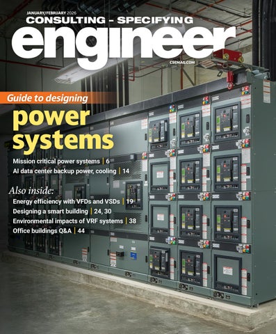
ON THE COVER: Backup power systems inside Mount Sinai Medical Center, Skolnick Surgical Tower and Hildebrandt Emergency Center. Courtesy: Laura Peters, CannonDesign
24 | Identify how to achieve a smart building with planning
Smart building design requires a smarter approach. Proactive design and operational decisions can help realize a smart building.
30 | Smart building tech boosts safety and performance in laboratory design
Laboratory design is being transformed by smart building technologies.
38 | Know the environmental impacts of VRF systems before specifying
p.30
Understand the various refrigerant options when specifying VRF systems in buildings.
AI data centers have shifted from ensuring uninterrupted uptime to prioritizing power stability and cooling continuity.
ENGINEERING INSIGHTS
19 | Smart motor control: unlocking energy efficiency with VFDs and VSDs
44 | Design office buildings with decarbonization and modularity in mind
Electric motors are essential in industrial applications. To improve efficiency and control, VFDs and VSDs are widely used.
p.14
p.38
In this roundtable, engineers discuss current trends for office buildings and where the industry is headed in the future.
CONSULTING-SPECIFYING ENGINEER ( Vol. 63, No. 1, ISSN 0892-5046, USPS PUBLICATION #901000 ) is published bimonthly by: WTWH Media, LLC; 1111 Superior Ave., Suite 1120, Cleveland, OH 44114. Periodicals postage paid at Cleveland, OH & additional mailing offices. POSTMASTER: Send address changes to CONSULTING-SPECIFYING ENGINEER, 1111 Superior Ave., Suite 1120, Cleveland, OH 44114. CONSULTING-SPECIFYING ENGINEER copyright 2026 by WTWH Media, LLC. All rights reserved. CONSULTING-SPECIFYING ENGINEER is a registered trademark of WTWH Media, LLC, used under license. Circulation records are maintained at WTWH Media, LLC, 1111 Superior Ave., Suite 1120, Cleveland, OH 44114. Telephone: 888-543-2447. Publications Mail Agreement No. 40685520. Return undeliverable Canadian addresses to: 1111 Superior Ave., Suite 1120, Cleveland, OH 44114. Rates for nonqualified subscriptions, including all issues: USA, $120/yr; Canada/Mexico, $150/yr (includes 7% GST, GST#123397457); International air delivery $260/yr. Except for special issues where price changes are indicated, single copies are available for $30 US and $35 foreign. Please address all subscription mail to CONSULTING-SPECIFYING ENGINEER, 1111 Superior Ave., Suite 1120, Cleveland, OH 44114. Printed in the USA. WTWH Media, LLC, does not assume and hereby disclaims any liability to any person for any loss or damage caused by errors or omissions in the material contained herein, regardless of whether such errors result from negligence, accident or any other cause whatsoever. CONSULTING SPECIFYING ENGINEER does not endorse any products, programs, or services of advertisers or editorial contributors. Copyright© 2026 by WTWH Media, LLC. No part of this publication may be reproduced in any form or by any means, electronic or mechanical, or by recording, or by any information storage or retrieval systems, without written permission from the publisher.
consulting-Specifying engineer— www.csemag.com
CSE2601_MAG_TOC_V5msFINAL.indd 3
January/February 2026
|3 12/30/25 3:23 PM
Your delivery is DELAYED... SWITCHGEAR DELAYS COSTING YOU TIME AND MONEY? TIRED OF BEING LIED TO ABOUT LEADTIMES? ARE YOUR DELIVERIES ALWAYS BEING...DELAYED?
ACCELERATE YOUR SCHEDULE OUR 25-36 WEEK LEAD TIME CUTS TOTAL PROJECT TIME BY AS MUCH AS 24 WEEKS CONTACT US TODAY TO SAVE TIME AND EXPENSE: lselectricamerica.com sales@lselectricamerica.com
LS Electric_pg04.indd 4
12/23/25 10:35 AM
CONTENT
NEWS&BUSINESS
CONTENT SPECIALISTS/EDITORIAL
VIEWPOINT
AMARA ROZGUS, Editor-in-Chief ARozgus@WTWHMedia.com
FRANCES RICHARDS, Associate Editor FRichards@WTWHMedia.com AMANDA PELLICCIONE, Marketing Research Manager APelliccione@WTWHMedia.com MICHAEL SMITH, Art Director MSmith@WTWHMedia.com
EDITORIAL ADVISORY BOARD DARREN BRUCE, PE, LEED AP BD+C, Director of Strategic Planning, Mid-Atlantic Region, NV5, Arlington, Va. MICHAEL CHOW, PE, CEM, CXA, LEED AP BD+C, Principal, Metro CD Engineering LLC, Columbus, Ohio CINDY COGIL, PE, FASHRAE, Vice President, SmithGroup, Chicago TOM DIVINE, PE, Senior Electrical Engineer, Johnston, LLC, Houston CORY DUGGIN, PE, LEED AP BD+C, BEMP, Energy Modeling Wizard, TLC Engineering Solutions, Brentwood, Tenn. PAUL ERICKSON, LEED AP BD+C Principal, Affiliated Engineers Inc., Madison, Wis. ROBERT J. GARRA JR., PE, CDT, Vice President, Electrical Engineer, CannonDesign, Grand Island, N.Y. JASON GERKE, PE, LEED AP BD+C, CXA, Senior Design Phase Manager, JP Cullen, Milwaukee JOSHUA D. GREENE, PE, Associate Principal, Simpson Gumpertz & Heger, Waltham, Mass. RAYMOND GRILL, PE, FSFPE, LEED AP, Principal, Ray Grill Consulting, PLLC, Clifton, Va. WILLIAM KOFFEL, PE, FSFPE, President, Koffel Associates Inc., Columbia, Md. WILLIAM KOSIK, PE, CEM, LEGACY LEED AP BD+C, Associate Principal, Sector Leader, HED, Chicago KENNETH KUTSMEDA, PE, LEED AP, Engineering Manager, Jacobs, Philadelphia DAVID LOWREY, Chief Fire Marshal, Boulder (Colo.) Fire Rescue JASON MAJERUS, PE, CEM, LEED AP, Principal, DLR Group, Cleveland CALEB MARVIN, PE, Senior Associate, Associate Partner, Certus Consulting Engineers, Dallas JUSTIN MILNE, PE, PMP, Senior Engineer, Southcentral Region, Jensen Hughes, Allen, Texas CRAIG ROBERTS, CEM, Account Executive, National Technical Services, McKinstry, Powell, Tenn. SUNONDO ROY, PE, LEED AP, Director, Design Group, Romeoville, Ill. JONATHAN SAJDAK, PE, Senior Associate/Fire Protection Engineer, Page, Houston RANDY SCHRECENGOST, PE, CEM, Austin Operations Group Manager/Senior Mechanical Engineer, Stanley Consultants, Austin, Texas MATT SHORT, PE, Project Manager/Mechanical Engineer, Smith Seckman Reid, Houston MARIO VECCHIARELLO, PE, CEM, GBE, Senior Vice President, CDM Smith Inc., Boston RICHARD VEDVIK, PE, Senior Electrical Engineer and Acoustics Engineer, IMEG Corp., Rock Island, Ill. TOBY WHITE, PE, LEED AP, Associate, Boston Fire & Life Safety Leader, Arup, Boston APRIL WOODS, PE, LEED AP BD+C, Vice President, WSP USA, Orlando, Fla. JOHN YOON, PE, LEED AP ID+C, Lead Electrical Engineer, McGuire Engineers Inc., Chicago
consulting-Specifying engineer — www.csemag.com
CSE2601_MAG_VIEW_V3msFINAL.indd 5
Engineering trends to watch in 2026 From electrification to commissioning, several trends and aspects of engineering are worth watching this year.
L
reporting IEQ for buildings will only ike many other technical media continue to grow. outlets, we track trends carefulBuilding commissioning is ly and filter them so that you can steadily expanding for newer buildfocus on the most important ones. ings and for facilities trying to Here are the key items I plan to watch achieve various energy goals. More in 2026: advanced commissioning Decarbonization was the includes artificial intellibuzzword a few years ago, gence and smart sensor-drivand now electrification joins en data collection to monitor it. While electrification does in real time and predict not guarantee decarbonizapotential problems or failtion, both topics are at the ures. With net-zero or pascore for both mechanical and sive buildings, owners want electrical engineers. Building Amara Rozgus, to know when additional owners want facilities that Editor-in-Chief power should be drawn from use low- and zero-carbon renewable energy sources, for examenergy sources and reduce greenple. Commissioning not only helps house gas emissions. prepare a building for successful There are, of course, challengoccupancy, it can also provide longes. When the source of electricity term effectiveness and efficiency. comes from decarbonized sources, Integrated building systems were such as solar or wind power, pressure covered in a research report and sevon the electrical grid is reduced. A eral pieces of content in 2025, and great deal of attention continues to be follow-up is already underway to pinpaid to the electrical grid to ensure point changes and trends. Integratit remains both resilient and able to ed systems can help with several of serve its customers. the above topics, but without buy-in Indoor environmental quality from the building owner and a solid (IEQ) encompasses indoor air quality understanding by the consultant, full (IAQ), acoustics, lighting and energy integration cannot successfully move use within a facility. Measuring IAQ forward. Stitching together entire may be a common practice; measursubsystems can be complex, and coning occupant health and productivity veying their value to building owners can be harder. While this might seem requires finesse and deep knowledge. rudimentary to a commissioning This can overlap with smart buildprofessional or an energy-efficienings, another trend to watch as our cy expert, gathering and reporting ability to mine data expands. cse all the data can be a massive project. Measurement and verification are not new, however, and this “trend” of January/February 2026
|5 12/30/25 3:24 PM
BUILDING SOLUTIONS EMERGENCY, STANDBY, BACKUP
Jocelyn Wildman, PE, CannonDesign, St. Louis
FIGURE 1: Double-ended secondary unit substation with primary selective switching arrangement and UL 1558 secondary. Courtesy: Kevin G. Reeves, CannonDesign
Guidance on designing reliable mission critical power systems Learn to design power systems for mission critical facilities with a focus on ensuring redundancy and resilience in normal, emergency and standby power systems.
6 | January/February 2026 CSE2601_MAG_BACKUP_V3msFINAL.indd 6
V
arious codes contribute to defining the minimum legal requirements for standby and emergency power systems; NFPA 70: National Electrical Code (NEC) Articles 700 Emergency Systems, 701 Legally Required Standby Systems and 702 Optional Standby Systems will always be applicable and provide foundational requirements but will be supplemented by additional codes based on the proposed occupancy type. As mission critical facilities span a wide variety of use types, it is important to understand the different sources of codes and standards that may affect base requirements for emergency and standby power. consulting-Specifying engineer — www.csemag.com
12/23/25 10:48 AM
For those mission critical facilities that fall within health care, NEC Article 517 Health Care Facilities will become applicable along with NFPA 99: Health Care Facilities Code, NFPA 101: Life Safety Code and Facility Guidelines Institute guidelines, all of which will reference additional codes and standards that may affect the minimum requirements for the normal and essential power systems. It should be noted that Article 517 amends Article 700, therefore Article 700 may not simply be replaced by 517; parts of 700 will still be applicable. Additionally, the Joint Commission publishes recommendations and requirements that they measure facilities against for granting hospitals accreditation. It is important to realize that these codes, standards and guidelines also define required periodic testing for the electrical systems, which will need to be carried out without interruption to facility operations. Alternately, mission critical facilities that, if disrupted, “would disrupt national security, the economy, [or] public health or safety” (NEC Article 708.1, Informational Note No. 1) can be classified as vital infrastructure by governmental authorities, which will trigger compliance with NEC Article 708 Critical Operations Power Systems (COPS). Some examples of these types of facilities are: • Emergency services such as 911 call centers, fire stations and police stations. • Communications infrastructure including data centers and cell towers. • Public utility plants. It’s imperative to collaborate with the authority having jurisdiction (AHJ) over the facility because risk assessments must be completed to define the resiliency level required for the power system. Also note that the scope of Article 708 is not constrained to standby power only, but the entire portion of the power system that serves the designated critical operations areas. Several facilities, however, fall outside of these classifications (i.e., not defined as strictly falling within the scope of Articles 517 or 708), but are still considered to be mission critical by either their stakeholders or the AHJ. consulting-Specifying engineer— www.csemag.com
CSE2601_MAG_BACKUP_V3msFINAL.indd 7
Generally, when an AHJ considers a facility or portion thereof “mission critical,” but not necessarily COPS, it is usually because the facility performs a function that, if disrupted, could pose a significant health and safety risk to personnel or the public. Power to those systems and processes would then fall under the requirements of NEC Article 701. While we usually understand Article 701 to pertain to systems that aid first responders — stair pressurization systems, elevators, etc. — additional items that an AHJ could classify as legally required could be:
FIGURE 2: Example of an interior generator plant for a regional hospital. The plant consists of three 1,500-kilowatt diesel gensets that are paralleled to support the essential power system. Courtesy: CannonDesign
• Laboratory ventilation, including fume hoods and associated make-up air where hazardous chemicals or biological agents are handled. • Systems required to maintain containment in biosafety level 3 and 4 areas. • Systems required to maintain safe conditions within hazardous manufacturing areas. It is important to determine and confirm a specific class and type of the emergency power supply systems required, as defined by NFPA 110: Standard for Emergency and Standby Power Systems, with the AHJ to understand the minimum requirements that will be applied to the project. Engineers must carefully research codes and standards such as the International Building Code, NFPA 99, NFPA
Learning
Objectives
u
• Understand the various code requirements for standby and emergency power for mission crit-ical facilities. • Learn strategies for power system redundancy and reliability. • Review ways to make the power system more redundant and resilient.
January/February 2026
|7 12/23/25 10:48 AM
BUILDING SOLUTIONS EMERGENCY, STANDBY, BACKUP
70, etc. and other industry-specific codes applicable to the project type to fully understand all baseline requirements.
‘
The facility’s
normal power should be designed to achieve a high level of reliability to maximize power continuity for the
’
entire facility.
Power systems beyond code requirements Many mission critical facilities are considered as such due to the business interests of their stakeholders — if operations are interrupted, great financial damage could be incurred. Alternately, some government-run facilities may not be on a level to require COPS but are still considered critical to continue operation; one example of this would be a state medical examiner’s office. In these cases, standby power requirements are defined according to NEC Article 702 and the facility owner’s requirements, but with the critical nature of the facility, the level of backup power will generally exceed what is strictly required by code. Owners frequently rely on engineers to define the appropriate levels of source and overall system redundancy. Normal power system considerations The facility’s normal power should be designed to achieve a high level of reliability to maximize power continuity for the entire facility as, generally, the on-site standby power source may only cover a limited portion. A regularly applied strategy for increasing normal power reliability is to receive two or more independent services from the utility service provider and arranging them so a single service or a combination of services can maintain the full capacity of the site. Some best practices to consider when employing this strategy are: • Request that the utility service provider (USP) provides circuits from different utility substations; the more independent the sources can be from one another, the greater the reliability we will achieve. A USP may even be able to provide feeds that originate from different power generation plants. Multiple sources should minimally originate from different utility transformers or buses so a single equipment failure does not disrupt both of the facility’s services and the service’s routing should be physically separated such that a single event does not damage both feeders. For example, if both feeders are to originate from the same utility substation,
8 | January/February 2026 CSE2601_MAG_BACKUP_V3msFINAL.indd 8
they should not be routed on the same poles or within the same duct bank. • Incoming utility feeders should be routed underground as much as possible. As overhead services are more vulnerable to weather- and traffic-related incidents, feeders should be routed within reinforced concrete duct banks whenever possible. Spare ducts should be provided to facilitate faster feeder replacement in a catastrophic event (i.e., a cable fault) or for general end-of-life replacement. • Incoming services should terminate on separate switchgear line-ups. When receiving multiple services, the service entrance switchgear should have an independent bus for each service that is electrically segregated in a main-tie-tie-main fashion. This type of arrangement allows facility loads to be normally split between each service and, if a given service is lost, the switchgear will automatically open the associated main breaker and close the tie breakers to restore power to all service entrance buses. An alternate scheme could be a “primary-alternate” arrangement where all loads are normally served by one service and if that service is lost, the switchgear automatically switches to the second service. However, the main-tie-tie-main arrangement offers higher redundancy because both the incoming service and the service entrance switchgear are redundant. Additionally, the dual tie breakers, as opposed to a contiguous line-up with one tie breaker, allow for complete bus isolation and some degree of physical separation of the line-ups, which will better isolate faults or facilitate maintenance and repairs without exposing personnel to risk of arc flash events. Careful consideration should be given to the downstream distribution system now that there is increased reliability of the normal power source. Within the context of a medium-voltage distribution system, multiple feeders should be extended to the various secondary unit substations located across the facility or site. At this level of the distribution system, where substations can still affect significant portions of the facility, these redundancy strategies should be considered: • Double-ended substations should be the default arrangement unless the project budget cannot support this strategy. While transformers do not fail very often under proper maintenance, lead consulting-Specifying engineer — www.csemag.com
12/23/25 10:48 AM
time and difficulty in replacement could introduce an extended shutdown. A substation that is arranged in a main-tie-main or main-tie-tie-main fashion with 2N transformers can greatly mitigate the risk of extended outages. • Primary-selective switching should be considered for double-ended substations and generally provided for single-ended substations. If the facility has been provided with multiple service entrances, the distribution must make use of each or all available services. If a utility source is lost, the service entrance switchgear will generally close its tie breakers and re-energize all of its buses. But if an outage originates within the switchgear itself or a given downstream feeder, power must be rerouted downstream of the outage. Double-ended units can facilitate this on their low-voltage bus, but single-ended units would need to be able to switch to an alternate primary feed. (Note: a double-ended unit without primary-selective switching would want to have medium-voltage circuits from two different medium-voltage buses.) • Consider more premium substation transformers over the standard vacuum pressure impregnated (VPI) type. As cast coil and oil-filled transformers have completely encapsulated or sealed windings, they have considerably higher durability than VPI type transformers. Strong consideration should be given to these types if the transformer is not going to be housed in a stable indoor environment where humidity and cleanliness are going to be well maintained. Each project would need to weigh the cost versus benefit of providing oil-filled or cast coil type transformers in lieu of VPI type.
Emergency and standby power considerations Similar strategies may apply when shifting focus on the system’s emergency and standby power elements, while additional items will become relevant as this portion of the system will serve the most critical functions of the facility, as well as code required systems. While it is true that some mission critical facilities will require full on-site backup and be able to operate in island mode for extended periods of time, many projects do not have a budget to warrant this extent of on-site generation, therefore some subsets of the facility will be offline during consulting-Specifying engineer— www.csemag.com
CSE2601_MAG_BACKUP_V3msFINAL.indd 9
a full utility interruption. For the portion that is backed up by on-site sources, the design must ensure those sources and associated distribution are always available. On-site power sources are usually provided in the form of engine-generator sets as, given sufficient fuel supply, they can provide indefinite and reliable runtime. Different facility code requirements will require on-site generators regardless of other mission critical goals; therefore, expanding the system capacity to cover what the NEC would consider “optional standby” (NEC Article 702) is a recommendation. In the implementation of a generator plant for a mission critical facility these are some key recommended best practices: Provide multiple generators arranged for at least N+1 capacity. Providing at least one redundant unit helps insulate the system from an equipment failure, also allowing for scheduled maintenance and testing to occur without degrading the system capacity. For large systems where the paralleling bus is split, N+2 would be recommended to give a redundant unit on each bus. On the other end of the spectrum, when considering small systems where a single generator may be sufficient, the design must provide a permanent connection for a temporary generator per NEC Article 700.3(F) to allow for maintenance to occur without interruption to the emergency power supply. Note that it is not possible to parallel a rollup generator with one or more permanent gensets; if there is a desire to provide extra capacity
FIGURE 3: Example of paralleling switchgear with touchscreen interface and three generator control sections. Unseen are the hot-swappable, dual redundant programmable logic controllers. Courtesy: Kevin G. Reeves, CannonDesign
January/February 2026
|9 12/23/25 10:48 AM
BUILDING SOLUTIONS EMERGENCY, STANDBY, BACKUP
‘
Having more,
smaller switches is better than fewer, larger
’
ones.
in a temporary fashion, the portion of the system that is planned to be supported by the roll-up genset would not be connected to the rest of the emergency power supply system while connected to the temporary unit. This type of arrangement would only be recommended for non-critical equipment needed to stand in the gap during scheduled maintenance. Segregate the paralleling switchgear bus with one or more tie breakers. Generally, paralleling switchgear consists of a single, contiguous bus connecting two or more gensets and for many applications, this is sufficient. However, when a given system has many loads required to be restored within 10 seconds or when critical heating, ventilation and air conditioning systems need to be restored as quickly as possible to maintain pressures in hazardous containment areas, the strategy of splitting the paralleling switchgear with a tie breaker allows multiple generators to begin accepting loads prior to achieving synchronization with each other; the tie breaker(s) will be normally open and will close to parallel the generators after loads have transferred. Generator and paralleling switchgear manufacturers will not guarantee that multiple units will parallel and accept loads within 10 seconds, thus this strategy becomes necessary once the 10-second load demand exceeds the capacity of the smallest genset on the system. Splitting up the paralleling switchgear bus with a tie-tie arrangement similar to the incoming service can help mitigate outages, whether planned or unplanned, on a given bus. (Note: the introduction of tie breakers into a paralleling line-up will preclude “on-board paralleling” offered by some manufacturers.) Diversify fuel types. The default emergency/ standby generator is the diesel generator for two main reasons: • Their ability to start and come up to rated speed quickly (NFPA 110, Type 10 even for large units), which is code required for NEC Article 700/Article 517 life safety loads. • The ability to store bulk fuel on-site, which may be a code requirement for certain projects located within seismic zones, although other factors can contribute to this requirement.
10 | January/February 2026 CSE2601_MAG_BACKUP_V3msFINAL.indd 10
However, the runtime for the diesel gensets is limited by the amount of fuel available. The on-site fuel supply is usually sufficient to either ridethrough the outage or allow for additional fuel to be delivered, but some past events like Hurricane Sandy, have demonstrated that reliance solely on diesel gensets may not be sufficient in areas with certain risk factors like hurricanes. Natural gas units have traditionally had limited application for level 1, type 10 systems but for mission critical facilities, a mixed generator plant could bring the benefits of both genset types with the diesel units providing quick response time and guarding against gas supply disruptions while the natural gas units provide indefinite runtime. As we shift downstream to standby system distribution, if the generator plant is operating at medium voltage, similar strategies for the unit substations should be applied. Downstream of the standby substations or for 480-volt systems, transfer switches and their downstream distribution become the set of next critical components that should be carefully arranged to minimize disruption to any given portion of the system. Recommended strategies include: Having more, smaller switches is better than fewer, larger ones. For most major distribution components, we can effectively mitigate source outages with double-ended arrangements, but a given transfer switch can become a critical single point of failure as both sources to a given load are supplied by the switch. It is generally recommended that the facility’s transfer switches complement the mechanical system’s redundancy strategy — each portion of the mechanical system is diversified between two or more transfer switches. For critical and life safety branches within a hospital, the design should consider providing at least two transfer switches per branch even if the load doesn’t seem to warrant it. Bypass isolation type transfer switches are generally used and recommended to allow bypassing of the transfer switch during maintenance activities, but some critical facilities may want to consider implementing external bypasses for their more critical transfer switches. This strategy allows annual testing to be executed while the switch is fully de-energized and can also alleviate consulting-Specifying engineer — www.csemag.com
12/23/25 10:48 AM
CASE STUDY: Mission critical lab achieves power redundancy and resiliency THIS LABORATORY was considered a mission critical facility, necessitating redundancy and resiliency for its power systems.
FIGURE 4: Example of single-ended secondary unit substation arrangement with secondary
The engineering team was tasked bus ties for partial with designing a state laboratory housredundancy. Courtesy: ing the state medical examiner, state CannonDesign police forensics labs and various chemical and biological testing labs including biosafety level 3 classified areas. While not requiring compliance with NFPA 70: National Electrical Code Article 708 Critical Operations Power Systems, this facility was considered mission critical due to multiple staterun services that were required to be approval was needed for this arrangement, the project is in a nonavailable at all times. The publicly funded project was required to seismic zone and the natural gas service provider are able to conadhere to a strict construction budget, which necessitated careful firm reliability for the fuel source. The generators were paralleled design to achieve satisfactory power resiliency. together at interior paralleling switchgear; a tie breaker was not Normal power: As efficiency was needed both on space and provided as all 10-second loads fit comfortably within the capacibudget, the facility was provided with exterior pad-mounted, solid ty of a single genset. dielectric, vacuum interrupter switchgear, which received two Downstream of the paralleling gear, transfer switches were feeds from the campus’s main substation. This type of switchcarefully arranged to ensure that power sources were diversified gear was chosen due to its low maintenance and robust confor various systems. Critical equipment and mechanical systems struction. Each feed was independently routed underground such as chillers, cooling towers, boiland served from different substation ers, pumps, laboratory exhaust fans, transformers. Additionally, the camair handling units and autoclaves pus received four independent primary While not requiring were split between transfer switchfeeds from the local utility provider set compliance with NFPA 70 es to allow a given piece of electrical up in a primary selective configuration. equipment to be out of service withThe pad-mounted switchgear proArticle 708, this facility was out shutting down a complete sysvided service to three single-ended tem. Additionally, all transfer switches unit substations within the building. considered mission critical. were bypass isolation type. Double-ended substations could not Finally, central uninterruptible be accommodated due to space limpower supply (UPS) power was needed for certain program eleitations. To achieve partial transformer redundancy, the substaments. Four smaller (150 kilovolt ampere) UPSs were providtion capacities were increased and secondary cross-ties were ed to diversify the source and each UPS was arranged with N+1 provided between the substations. Each cross-tie was sized to batteries, as well as an external bypass for interruption free provide 66% capacity to the reliant substation and the main and maintenance. tie breakers were interlocked with a simple kirk key scheme. This While the overall project was constrained by budget, which setup allowed for a single substation transformer outage without didn’t allow for all ideal strategies to be implemented, the final complete reliance on the generators for an extended period. design was able to achieve a satisfactory level of redundancy Standby power: The facility was provided with four 1,300-kiloand resilience. Having a very high reliability on the normal power watt natural gas generators to supply emergency and standby source allowed for a more cost-efficient standby power system, power. Natural gas was chosen due to its availability and ability which focused on the most critical aspects of the facility. to provide indefinite runtime. While authority having jurisdiction
‘
’
consulting-Specifying engineer— www.csemag.com
CSE2601_MAG_BACKUP_V3msFINAL.indd 11
January/February 2026
| 11 12/23/25 10:48 AM
BUILDING SOLUTIONS EMERGENCY, STANDBY, BACKUP
‘
Part of designing for unplanned outages includes confining an interruption as locally as possible; the nearest upstream breaker to a
’
fault should be the device to clear the fault.
Insights
u
csemag.com
Power system insights u There are many
building types that can be considered mission critical facilities. While “mission critical facilities” lacks specific definition within a code or standard, this building category can encompass buildings of diverse sizes and complexities.
u From fire and
ambulance stations to large-scale manufacturing facilities, the critical nature and the level to which it must remain operational under all circumstances need to be carefully defined and designed for.
u Power systems are
complex within mission critical facilities and must be designed to both meet code and achieve high reliability.
strain that the facility would otherwise experience during transfer switch equipment replacements. Open transition versus closed transition: Transfer switches are generally provided as either open transition, break-before-make or closed transition, make-before-break and there are benefits and drawbacks to each. Open transition switches are more economical and one could argue, more reliable due to their reduced complexity. However, loads served by open transition switches will experience a short interruption when returning to normal power, which may be undesirable for certain loads. Conversely, closed transition switches avoid interruption on return to normal power however they are more expensive and require a shut trip strategy to be implemented to ensure that the sources are never paralleled for longer than the rated number of cycles. Each portion of a system should be evaluated to determine which style is appropriate: if the switch serves an uninterruptible power supply, closed transition would not be needed and some cost can be avoided; if the switch serves lighting in patient areas of a hospital, closed transition may be desired to avoid alarming building occupants. Selectively coordinate the entire system. Part of designing for unplanned outages includes confining an interruption as locally as possible; the nearest upstream breaker to a fault should be the device to clear the fault. Improper coordination of the trip curves of the breakers or fuses in a system could result in a broader outage than was strictly required to remedy the immediate danger. Constraining transfer switch capacity not only aids in avoiding “too many eggs in one basket,” this approach also flattens the distribution which will improve selective coordination. While selective coordination is code required for emergency/
12 | January/February 2026 CSE2601_MAG_BACKUP_V3msFINAL.indd 12
life safety, legally required standby, COPS, etc., it innately increases the reliability of the entire system if applied broadly. Additionally, a shallower distribution system will help to avoid the cost of using 30 cycle rated transfers switches.
Distribution design to maximize uptime When approaching standby and emergency power system design, engineers are designing a system that automatically restores power when it is lost unexpectedly. However, good design will also consider strategies to mitigate planned outages that a facility may need to impose to execute general maintenance, code required testing or system modifications. Many of the strategies addressed above will inherently help with this but some additional areas that may need careful planning are: • Site wide distribution of medium voltage circuits. If each unit substation on the site is provided with two different primary circuits, these circuits must be routed such that a shut down on one does not affect the other. This can become a complex analysis when multiple circuits serving many unit substation pass through the same manhole; if a manhole needs to be accessed by personnel, all circuits passing through need to be de-energized without causing an interruption to the system. • Splitting critical loads between different panelboards, transfer switches and sides of double-ended equipment. Equipment that serves critical processes and mechanical systems should have diversified sources. Sometimes the tendency can be to group like things together — like all chilled water pumps — but a better arrangement would be to have a chiller, one cooling tower, one condenser water pump and one chilled water pump on a given transfer switch and a similar set of equipment on a different transfer switch. Additionally, these switches could be fed from different sides of a double-ended substation. Even if maintenance is required somewhere in the system, at least a portion of the chilled water system will be maintained throughout. cse Jocelyn Wildman, PE, is a Senior Electrical Engineer with CannonDesign. Her focus is power systems design for health care and laboratory facilities and campuses. consulting-Specifying engineer — www.csemag.com
12/23/25 10:48 AM
Nominate a team member to the 2026 40 Under 40 award program! To qualify for 40 Under 40, nominees must be 40 years of age or younger (as of May 1, 2026) and be nominated by a supervisor, academic adviser, peer, mentor, public relations professional, project leader or other person directly involved in their career progress. Nominations due: Jan. 30, 2026
Supporting materials due: Feb. 6, 2026
Nominate a colleague who is 40 years of age or younger at www.csemag.com/40under40
HouseAd_DigitalEdition_pg13.indd 13
12/30/25 3:15 PM
BUILDING SOLUTIONS EMERGENCY, STANDBY, BACKUP
Sam Buscemi, PE, NCEES, Affiliated Engineers Inc., Madison, Wisconsin
How to achieve AI data center backup power, cooling
AI data centers have redefined the power paradigm in design, shifting from ensuring uninterrupted uptime to prioritizing power stability and cooling continuity.
F
Learning
Objectives
u
•D ifferentiate between backup power expectations in traditional colocation data centers versus AI data centers, including how reliability targets and risk profiles shape system design. •U nderstand how design priorities in AI data centers, including maintaining cooling loops, protecting valuable hardware and enabling controlled shutdowns, are changing the application of uninterruptible power supply, battery energy storage and hybrid backup systems. •E valuate alternative power design strategies that balance resiliency, emissions/permitting hurdles and practical equipment availability for supporting AI workloads.
or decades, the benchmark of excellence in data center design was simple to state and expensive to achieve: keep everything on, all the time. Extensive fleets of diesel generators, redundant uninterruptible power supply (UPS) systems and mechanical plants enabled data centers to operate indefinitely without the grid. Downtime for financial institutions, hospitals or e-commerce platforms translated into revenue loss, compliance risk or threats to public safety. What mattered most was keeping services running. Hardware was expendable, but uptime was not. The rise of artificial intelligence (AI) has shifted the equation. AI data centers concentrate dense racks of graphical processing units (GPUs) that can draw up to 130 kilowatts each, cooled by direct-tochip liquid systems with tight flow and temperature tolerances. A single high-density AI compute cabinet is estimated to cost between $2 million and $3 million and when multiplied across the hundreds of units deployed in a modern facility, the hardware investment alone quickly climbs into the hundreds of millions. Protecting that capital investment is no longer just an operational concern — it is a business imperative.
Uptime versus asset protection AI facilities operate under fundamentally different economics than traditional colocation providers. Training workloads can be checkpointed and resumed, making brief interruptions tolerable. Customers expect occasional capacity constraints, such
14 | January/February 2026 CSE2601_MAG_MCF_V3msFINAL.indd 14
as when new model launches prompt providers to throttle resources to manage demand. Some downtime is acceptable, but hardware damage is not. The principal responsibility for consulting engineers in AI data centers has shifted from maximizing uptime to protecting GPU assets and preventing catastrophic loss. The reason is twofold. First, each GPU represents an enormous upfront investment and once damaged, the capital loss is permanent with no recovery path. Second, the direct-to-chip liquid cooling used in these systems introduces an acute vulnerability: without continuous coolant flow, the risk of thermal runaway is immediate and severe. This stands in sharp contrast to the traditional air-cooled data hall. In those environments, a loss of cooling might mean a gradual rise in data hall temperature over minutes or even hours, allowing workloads to be throttled down or shifted before equipment becomes at risk. With GPUs, however, sudden power interruptions or cooling failures can push hardware past safe limits in seconds, causing thermal overload, electrical stress and cascading failures across densely packed racks. As a result, the focus has shifted away from uptime at all costs toward ensuring that systems remain stable long enough for workloads to throttle down and shut off safely. This evolution forces a reconsideration of what “mission critical” entails, with resiliency measured by the ability to protect GPUs rather than keep every workload running indefinitely. Instead of covering every kilowatt of information technology (IT) and cooling load with diesel generator backup, the industry is shifting toward hybrid strategies, including battery energy storage systems (BESS), thermal energy storage, selective generator coverage and advanced protection schemes and smoothing load fluctuations of GPU servers. These designs now prioritize protecting high-value hardware investconsulting-Specifying engineer — www.csemag.com
12/23/25 10:50 AM
ments rather than simply maximizing availability.
The criticality of cooling To understand this shift in design focus for AI data centers, it helps to start with the GPU itself. GPUs were originally designed to handle the rendering of computer graphics. They are specialized hardware built to offload display tasks from the central processing unit (CPU). Unlike CPUs, which are optimized for a wide range of instructions, GPUs excel at performing a massive number of simple mathematical operations simultaneously. That parallel architecture soon proved valuable beyond graphics. GPUs fueled the cryptocurrency boom, crunching blockchain algorithms at scale. They currently sit at the core of AI, training and running the world’s largest machine learning models. As GPUs advanced, they’ve reached unprecedented levels of power density, with a thermal safety window measured in seconds. The energy they draw today far exceeds what air cooling can handle, forcing the industry to adopt directto-chip liquid cooling. In this approach, coolant flows through cold plates mounted directly on the processors, carrying heat away at the source through a closed-loop system. Managing this closed-loop effectively is the role of the coolant distribution unit (CDU), which bridges the rack-level liquid circuit to the facility’s chilled-water system. A CDU is a closed-loop system that circulates liquid through the GPUs to remove heat. This liquid cooling loop is referred to as the technology cooling system (TCS) loop. Once the loop is filled, pumps inside the CDU drive coolant through the supply and return manifolds connected to each cabinet. The coolant absorbs heat at the GPU cold plates and then returns to the CDU, where the heat is transferred through a heat exchanger into the building’s chilled-water system. Keeping GPUs alive requires keeping coolant moving. If coolant circulation stops for even a few seconds under full load, junction temperatures can soar beyond safe limits, permanently damaging the silicon. If pumps stall or flow is interrupted, thermal runaway is almost immediate. This cooling loop doesn’t need to operate indefinitely during a consulting-Specifying engineer— www.csemag.com
CSE2601_MAG_MCF_V3msFINAL.indd 15
FIGURE 1: Direct-to-chip liquid cooling manifold at the rack level. The manifold distributes facility supply and return water across multiple graphical processing units within the rack, ensuring stable flow and temperature control for highdensity compute loads. Courtesy: Affiliated Engineers Inc.
power loss, but it must maintain flow long enough for workloads to throttle back and shut down in an orderly way within minutes. Because the TCS loop is sealed and independent, the same fluid is continuously recirculated, maintaining tight control over chemistry, flow and pressure while isolating the electronics from the facility water. In most data centers, the loop inside the CDU is filled with a water-glycol mixture, typically 25% to 35% glycol, to prevent freezing, reduce corrosion and provide reliable thermal performance. Moreover, because the microchannels inside the GPU cold plates are so narrow, the coolant must be extremely clean. Even tiny particles, rust or biological growth can cause clogs that reduce flow and quickly lead to overheating. To protect against this, CDUs use fine filters, chemical treatments and continuous monitoring to keep the coolant within tight specifications for purity, pH and conductivity. Regular maintenance ensures the system stays reliable and protects the GPUs it serves. Beyond circulation and filtration, CDUs also serve as intelligent control hubs. More than just pumps, they are sophisticated control packages typically built with N+1 redundancy and dual power
‘
The focus has shifted away from uptime at all costs toward ensuring that systems remain stable long enough for workloads to throttle down and
’
shut off safely.
January/February 2026
| 15 12/23/25 10:50 AM
BUILDING SOLUTIONS EMERGENCY, STANDBY, BACKUP
‘
Expensive GPU
assets require UPS power. That statement reflects both economic reality and operational necessity.
’
supplies or deployed in 2N pairs for full fault tolerance, making them a true mission-critical element of modern AI data centers. They regulate flow, temperature and pressure to ensure each cold plate receives an adequate amount of coolant. Advanced sensors and feedback loops enable the CDU to respond in real-time to changes in load, thereby protecting GPUs from thermal spikes. This setup delivers exceptional thermal efficiency but also leaves a razor-thin margin for error. Because of their criticality, CDUs are almost always placed on UPS-backed power. In many AI facilities, UPS systems now cover not only IT racks but also CDUs, pump controllers and monitoring systems. This represents a fundamental shift from traditional colocation design, where UPS was primarily reserved for IT loads, while cooling infrastructure relied on generators. The logic is simple: CDUs are lightweight loads compared to GPUs, yet their failure can instantly jeopardize hundreds of millions of dollars in hardware. The TCS loop is only half the equation. At the facility level, the heat absorbed by rack-level coolant must be rejected into a chilled-water loop. This secondary loop acts as the bridge between IT hardware and mechanical infrastructure. Heat exchangers inside the CDU transfer energy from the server coolant to the facility water system (FWS) loop, where it is carried away to be dissipated by chillers or cooling towers. The FWS serves a dual role: supplying cooling water to the CDUs and supporting air-side cooling for fan walls. To ensure reliability, the pumps and chillers that drive this system are often backed by generators. Another layer of resilience comes from thermal storage tanks, which hold chilled water that can be drawn on if chillers go offline. When sized appropriately, these tanks enable the pumps to continuously circulate stored chilled water, thereby reducing the need to run chillers on backup power and providing sufficient time for an orderly shutdown. This two-tiered system, consisting of an technology cooling system loop and a FWS loop, creates both redundancy and complexity. On the one hand, it allows precise thermal management inside the white space. On the other hand, it makes the data center critically dependent on the reliability of chillers, pumps and supporting mechanical systems.
16 | January/February 2026 CSE2601_MAG_MCF_V3msFINAL.indd 16
If the facility water loop falters, even perfectly functioning CDUs cannot shed heat indefinitely.
Delivering power stability Having examined how cooling infrastructure underpins the survival of GPU clusters, it’s important to shift focus to the electrical backbone that keeps everything powered. The reliability of chillers and pumps is only one side of the equation; the other is ensuring that the electrical distribution system can deliver clean, stable power to the racks themselves. Uninterruptible power supply: Expensive GPU assets require UPS power. That statement reflects both economic reality and operational necessity. The first reason is straightforward: UPS systems protect against surges, sags and short-duration power quality issues. Even in areas with a relatively stable grid, momentary voltage disturbances are common. Without UPS protection, those disturbances can propagate through the switchboard and directly into sensitive electronic hardware. The cost of a fried GPU board or failed power supply is not trivial and with racks easily worth millions of dollars, the risk exposure is too great. The second reason is tied to the transient nature of AI workloads. Training servers frequently draw rapid bursts of current that exceed the steady-state capacity of the electrical distribution system. The UPS, with its battery and power conditioning capabilities, supplements that demand and stabilizes the voltage delivered to the servers in accordance with the Information Technology Industry Council curve. If the utility voltage drifts outside the acceptable range for IT equipment, servers could shut down abruptly, causing both computational interruptions and significant disturbances on the utility side due to the sudden loss of load. In this way, the UPS not only provides shortterm energy buffering but also smooths the electrical profile of highly dynamic AI training environments. Finally, UPS runtime provides a critical operational buffer. For AI training jobs, shutting down immediately means losing hours or even days of progress. But if workloads have five minutes of UPS support, they can checkpoint, save state and exit cleanly. In practice, a UPS runtime of five to seven minutes is sufficient for most facilities. It doesn’t need to carry the load for an hour; it just needs to buy time for an orderly transition to shutdown. consulting-Specifying engineer — www.csemag.com
12/23/25 10:50 AM
CASE STUDY: How to design an AI data center campus backup power system A COORDINATED APPROACH to an AI data center campus backup power system allowed for time and money savings.
With this understanding, the design team pursued a revised strategy that dramatically reduced reliance on diesel. Instead of deploying generators for the full facility, only two 3 MW Tier 4 diesel units were installed, dedicated to pump and control coverA new 100 megawatts (MW) artificial intelligence (AI) data age. These units provided a safety net for maintaining circulation center campus in Texas provides a clear example of how backduring prolonged outages without the cost and complexity of fullup strategies are shifting in response to the realities of graphisite backup. cal processing unit (GPU)-dense workloads. For the remainder of the system, a 20 megawatt-hour lithiWhen the project was first conceived, the design followed the um-ion battery energy storage systems (BESS) installation was traditional model: large-scale diesel backup intended to keep deployed to support chiller operation and other selective loads. the entire site running indefinitely. The initial plan called for This containerized battery system was designed to deliver five more than a dozen utility-scale generators, enough to cover the minutes of runtime at scale, bridging the gap entire 100 MW information technology (IT) between a utility outage and an orderly GPU and cooling load. This approach aligned with shutdown. Two 40,000-gallon chilled water colocation design practices, but it came with A deeper technical storage tanks were also added, creating addifamiliar problems. tional thermal buffer capacity without drawing The permitting process was expected to review showed that electrical power. be challenging, driven by strict emissions The integrated controls tied uninterruptible requirements from the Environmental Profull generator coverage power supply (UPS), BESS, thermal storage and tection Agency and additional oversight from was unnecessary. generators into a coordinated sequence. Upon the Texas Commission on Environmental utility loss, the UPS carried GPU loads long Quality. Securing approval for a large fleet of enough for checkpointing. Simultaneously, the diesel units meant extensive review, detailed BESS maintained chiller operation and the diesels stabilized the computational fluid dynamics modeling and protracted negotipump and control systems. Once workloads shut down, the sysations over runtime and emissions limits. These hurdles made tem could transition into a steady-state “safe mode” powered only it clear that relying on traditional generator coverage would sigby selective generator coverage and stored chilled water. nificantly delay the project’s schedule in a market where speed The results were substantial. Generator capacity was reduced to operation is essential. from 100 MW down to 6 MW, cutting more than $50 million from A deeper technical review showed that full generator covcapital costs. The smaller diesel installation cleared permitting in erage was unnecessary. The critical factor was not indefinite less than nine months, compared to the 24 to 30 months expectuptime for all GPUs but rather maintaining a stable cooling ed for a full-scale fleet. With the simplified backup architecture, loop long enough for workloads to checkpoint and shut down the facility is tracking for operation nearly a year ahead of schedgracefully. Detailed modeling demonstrated that the GPU racks ule, accelerating more than $30 million in revenue. could tolerate a controlled shutdown within 90 seconds, proThis project illustrates how reframing “mission critical” around vided coolant flow was maintained. The truly indispensable protecting hardware and ensuring controlled shutdown, rather loads during an outage were limited to approximately 5 MW of than indefinite uptime, delivers not only technical reliability but pump power and controls, far less than the full IT load originally also economic and environmental advantages. assumed.
‘
’
UPS systems solve the immediate problem of keeping workloads stable long enough to shut down, but they are not designed for prolonged outages. That gap has traditionally been filled by generators, which can carry loads for hours or days once fuel is available. The challenge now is determining where generator coverage is truly necessary, as relying on them universally has become less practical and far more difficult to justify. Generator deployment: In the colocation era, generators were considered essential, with every critconsulting-Specifying engineer— www.csemag.com
CSE2601_MAG_MCF_V3msFINAL.indd 17
ical load supported by diesel capacity sized for indefinite runtime and secured through fuel contracts. That approach is increasingly difficult to sustain. Large diesel installations face permitting challenges as local jurisdictions and communities push back over air quality and noise concerns. Even with after-treatment systems, emissions remain under scrutiny and many regions are imposing stricter limits on runtime hours. On top of that, procurement cycles for large generators often extend 12 to 18 months, which is a serious constraint in an industry where speed to January/February 2026
| 17 12/23/25 10:50 AM
BUILDING SOLUTIONS EMERGENCY, STANDBY, BACKUP
FIGURE 2: Battery energy storage system lineup, shown as a containerized solution installed on an exterior pad. Incoming and outgoing conductors are terminated underground, with the system sited independently from the main building. Courtesy: Affiliated Engineers Inc.
Insights
u
csemag.com
AI data center power insights u Traditional colocation
data centers have long been designed for “five nines” availability, relying on generator-backed systems sized to support nearly 100% of IT and cooling loads. AI data centers, however, introduce new challenges.
u Direct-to-chip liquid
cooling systems require only enough ride-through power to execute orderly shutdowns, while the scale and availability of standby generators are increasingly constrained. This is driving the development of new architectures that integrate battery energy storage systems, thermal energy storage and selective generator backup for critical cooling infrastructure.
market is paramount. Beyond the delays, generators also demand significant space, foundations and fuel infrastructure, all of which add cost and complexity. As a result, AI facilities are adopting a more selective approach to generator deployment. Instead of backing every load, generators are reserved for systems that truly require extended runtime, such as communication networks, core switching equipment and critical portions of the cooling loop. Although keeping GPUs powered for days during an outage is neither practical nor necessary, maintaining connectivity and cooling management protects the broader facility and ensures a controlled restart when utility power is restored. BESS: BESS are emerging as a practical alternative to diesel generators in certain applications, offering both scale and flexibility. Traditionally, BESS have been deployed at the utility or substation level, where operators use large battery banks to provide backup capacity, stabilize the grid or even sell stored energy back into the market during peak demand periods. Typically housed in modular 20- or 40-foot containerized units, BESS can deliver up to 3 megawatts of power with 12 megawatt-hours of storage. At that scale, a single containerized system is large enough to back an entire pad-mounted transformer behind the meter and multiple units can be combined to support much larger facilities. Their modular nature means they can be added in phases, expanding in step with the growth of a data center campus without
18 | January/February 2026 CSE2601_MAG_MCF_V3msFINAL.indd 18
requiring the upfront footprint of a generator farm. Beyond sheer capacity, BESS brings a set of advantages that make it increasingly attractive for data center use. They bypass many of the air-permitting hurdles that slow diesel deployments. Because batteries respond instantly, they eliminate the startup delay inherent to generators. In addition to providing ridethrough during utility events, BESS can participate in grid services, demand charge management and renewable integration, offering a layer of operational and financial flexibility that generators cannot. For data centers, this means a BESS installation can act like a UPS at a massive scale, extending five-minute runtime to entire cooling plants, network cores or even entire building feeders. Just as importantly, they avoid the fuel logistics and maintenance overhead of diesel, making them a cleaner, faster and more adaptable option for modern facilities.
Layered strategies foster power resilience The future of backup power in AI data centers is moving toward smarter, more integrated systems. UPS and BESS will increasingly operate as a single layer of protection, coordinated directly with workload management software to optimize both cost and efficiency. Advances in workload-aware shutdown logic and thermal storage will extend ridethrough without excessive electrical infrastructure. At the same time, small modular nuclear reactors hold the potential to reshape long-term campus power with stable, scalable baseload generation. What emerges is a shift away from blanket redundancy toward precision. The goal is not to keep every system running indefinitely, but to protect the assets that matter most: GPU clusters, network cores and the cooling systems that sustain them. UPS delivers clean power and short-term ride-through, generators are applied selectively where extended runtime is essential and BESS adds flexible, scalable coverage. Together with thermal storage, these strategies form a layered approach that balances resilience, cost and sustainability for the next generation of AI facilities. cse Sam Buscemi, PE, NCEES, is a Senior Project Engineer at Affiliated Engineers Inc., where he leads mission critical electrical design for large-scale data centers and high-reliability facilities. consulting-Specifying engineer — www.csemag.com
12/23/25 10:50 AM
BUILDING SOLUTIONS MOTORS AND DRIVES
Michelle Stark, PE, CDM Smith, Latham, New York; and Jincy Jose, CDM Smith, Chennai, India
Smart motor control:
Unlocking energy efficiency with VFDs and VSDs
Electric motors are essential in industrial applications, converting electrical energy into mechanical motion for systems like pumps, fans and conveyors. To improve efficiency and control, VFDs and VSDs are widely used.
E
lectric motors are the backbone of industrial motion, converting electrical energy into mechanical force to drive pumps, fans, conveyors and countless other systems. To optimize their performance, engineers increasingly rely on speed control technologies, such as variable frequency drives (VFDs) and variable speed drives (VSDs). These technologies not only enhance energy efficiency and process control but also reduce mechanical stress and maintenance needs, making them essential tools in modern engineering applications. A VFD is an electronic device used to control the speed and torque of an alternating current (ac) motor by varying the frequency and voltage of the power supplied to it. The frequency of the ac power determines the motor’s speed and the voltage affects the torque. By adjusting the speed and torque, the VFD can precisely control motor performance during startup, operation and shutdown of the motor. A VFD adjusts the motor’s speed to match the specific mechanical load requirements, which improves energy efficiency, reduces mechanical stress, extends motor life, lowers noise and vibration and enables precise process control. VFDs are widely used in water and wastewater treatment plants, heating, ventilating and air conditioning (HVAC) systems, pumps, fans, compressors, industrial machinery, conveyors and escalators. A VFD contains three main components: • The rectifier converts incoming ac power to direct current (dc).
consulting-Specifying engineer— www.csemag.com
CSE2601_MAG_DRIVES_V4msFINAL.indd 19
• The dc link stabilizes the dc power using capacitors. • The inverter converts the dc back to ac at variable frequency and voltage. A VSD is a motor controller that regulates the speed and torque of an electric motor (ac or dc type motor) by adjusting the input voltage and frequency. VSDs are used in industrial and infrastructure applications to optimize energy use, reduce wear and tear and improve process control. For ac motors, a VSD sits between the electrical u supply and the ac motor so that ac power from the • Understand the main enters the VSD, a rectifier converts this ac to fundamental principles of dc, the dc is then smoothed by capacitors and an variable frequency drives inverter then converts the dc back to ac at a vari(VFDs) and the motor types applicable for VFD able frequency and voltage. operation. For dc motors, drives can vary the armature • Explore how VFDs voltage and field current to adjust speed. Pulseenhance energy width modulation (PWM) is also a technique for efficiency and operational performance in industrial controlling the speed and torque of a dc motor by systems by enabling rapidly switching a power source on and off to conprecise speed control based on real-time system trol the average voltage or current to a load. This demand. enables accurate regulation of the motor’s average • Gain an in-depth voltage, promoting both efficient performance and understanding of power dependable operation. quality challenges related to VFD implementation, Servo drives are another type of VSD that are such as the generation specialized high-performance drives. These drives of electrical harmonics, are paired with brushless motors (ac or dc servo electromagnetic interference and voltage motors) and feedback devices to provide defined fluctuations and learn torque, speed and position control in automated practical mitigation strategies. systems. The VSD also is used for energy efficiency,
Learning
Objectives
January/February 2026
| 19 12/23/25 10:52 AM
BUILDING SOLUTIONS MOTORS AND DRIVES
FIGURE 1: Photograph of stand-alone variable frequency drives (VFDs) in an environmentally controlled electric room. Each VFD controls one motor located in a pump room in the same building. Courtesy: CDM Smith
process optimization, reduced maintenance and environmental benefits. A VFD is specific to ac motors and adjusts the frequency and voltage of ac power to control the speed of an ac induction motor. A VSD is a broader term that refers to any device that controls motor speed by varying input parameters like voltage, frequency or current and includes both ac and dc motor control. Therefore, all VFDs are VSDs, but not all VSDs are VFDs. When working with ac motors that need energy-efficient speed control, VFDs are required. However, when an application involves variable speed control for dc motors, such as servo systems, dc output VSDs are required. VSDs are the chosen technology for broader applications, including dc motors and systems requiring fine-tuned speed adjustments. VSDs are also used when a system requires flexibility in control methods and when incremental motion control or positioning accuracy is needed.
Impact of VFDs on pump performance The VFD is crucial in modern pump systems because it provides precise control over motor speed and improves overall system efficiency. Pumps have operated in an on/off mode or via mechanical throttling to control flow, which often leads to high energy consumption and mechanical stress. Using a VFD allows the pump speed to be modulated smoothly, according to system demand, thereby significantly reducing energy usage and improving operational stability. By adjusting the
20 | January/February 2026 CSE2601_MAG_DRIVES_V4msFINAL.indd 20
frequency and voltage supplied to the motor, VFDs enable pumps to operate closer to their best efficiency point across a wide range of flow rates. In terms of performance analysis, studies show that pumps equipped with VFDs consume less power at partial loads compared to fixed-speed pumps. For example, when the system demand decreases, a VFD reduces motor speed, thereby cutting power consumption following the cube law of pump energy (power ∝ speed3). This results in substantial energy savings, especially in processes where the demand fluctuates frequently. Additionally, VFDs reduce mechanical wear and tear by ensuring smooth acceleration and deceleration during pump start-up and shutdown, thus limiting inrush currents and pressure surges. The influence of VFD implementation on pump operation is significant. Unlike fixed-speed systems, VFD-controlled pumps can maintain constant pressure or flow rate by dynamically adjusting speed to match system requirements. This adaptability improves process stability and reduces the likelihood of cavitation, which is common during low-flow conditions in traditional throttled systems. Moreover, VFDs offer protection features such as overload and over-voltage protection, fault diagnostics and even short-circuit protection, thus reducing the need for separate protective devices and further enhancing system reliability. Operationally, the impact of VFDs on pumping systems extends beyond energy savings. VFDs offer improved flexibility in system control, enabling operators to fine-tune pump performance remotely and respond to process changes in real time. However, challenges such as harmonic distortion introduced into the power supply must be addressed using appropriate filtering techniques. Despite the higher initial cost of VFD installation, the return on investment is realized through longterm energy savings, reduced maintenance costs and extended equipment lifespan.
Applicable motor types for VFD operation VFDs are widely used in industrial applications to control the speed and torque of electric ac motors by adjusting the frequency and voltage supplied to the motor. consulting-Specifying engineer — www.csemag.com
12/23/25 10:52 AM
However, not all types of motors are equally suited for operation with VFDs. Because of its rugged construction, reliability and cost-effectiveness, the most used motor type in conjunction with VFDs is the three-phase induction motor (asynchronous motor). These motors are well-suited for variable speed applications because they have simple designs without brushes or commutators, which makes them durable and ideal for harsh industrial environments. VFDs can efficiently control the speed of threephase induction motors across a wide range of applications, such as pumps, fans and conveyors. Another motor type applicable for VFD operation is the synchronous motor, typically used in power factor correction applications and in applications where constant speed operation is essential. Although synchronous motors can be operated by VFDs, they require additional sensors such as an encoder or resolver feedback to maintain synchronization between the motor and drive system, making them less common when compared to induction motors. Permanent magnet synchronous motors are gaining popularity in VFD applications where higher efficiency, precise speed control and better torque performance are required. Single-phase induction motors are generally not recommended for VFD operation, though specialized drives exist for limited small-scale applications. However, VFDs can be used to derive a threephase power output from a single-phase input, which is especially valuable in remote locations where a three-phase power supply is unavailable and larger three-phase motor loads must be supported. Overall, the selection of a motor for VFD operation depends on application requirements, such as efficiency, control precision, torque, cost and operating environment. Proper motor-VFD matching ensures optimal performance, energy efficiency and system reliability in industrial applications.
Harmonics and power quality challenges in VFD applications VFDs are widely adopted in industrial applications because they can provide efficient motor speed control and energy savings. However, their use introduces significant power quality challenges, primarily in the form of electrical consulting-Specifying engineer— www.csemag.com
CSE2601_MAG_DRIVES_V4msFINAL.indd 21
harmonics. Harmonics are voltage or current waveforms delivered at frequencies that are integer multiples of the fundamental power frequency (usually 50 or 60 hertz, known as Hz). These are generated because VFDs convert the incoming ac power into dc through a rectifier and then use PWM to synthesize the variable frequency ac output. This process, while effective for controlling motor speed, produces nonlinear current waveforms that distort the ideal sinusoidal supply current. Harmonics will be imposed on the power system upstream of VFDs because of how they create adjustable frequency output. Excessive harmonics on the power system creates a power quality issue. Poor power quality can result in equipment malfunctioning or failure and could require standby generators to be oversized. At an industrial process facility such as a water/ wastewater treatment plant — where most loads are motor loads controlled by VFDs and standby generators are used to back up the utility source — the amount of nonlinear loading is a concern. IEEE 519: Standard for Harmonic Control in Electric Power Systems quantifies excessive harmonics as it concerns the utility power source. This standard establishes harmonic constraints at the point of common coupling between the utility provider and customer under steady-state conditions. The objective is to ensure that poor power quality within one customer’s service does not negatively impact neighboring utility customers. VFDS are nonlinear loads. The basic VFD is a six-pulse model. It creates 5th, 7th, 11th, 13th, 17th, 19th and so on harmonics (multiples of the fundamental power frequency). A better VFD is a 12 pulse model. It creates 11th, 13th, 23rd, 25th, etc. harmonics. An even better VFD is an 18-pulse model. It creates 17th, 19th, 35th, 37th and so on harmonics. In general, the lower the harmonic number, the higher the current component. Another concern with harmonic distortion is its effect on power system efficiency and reliability. Harmonics can cause excessive heating in transformers, motors and cables, leading to premature equipment aging or failure. Harmonics also contribute to neutral conductor overloading in three-phase systems, increase losses in power distribution networks and may interfere with sensitive electronic equipment, leading to malfunction or data errors.
FIGURE 2: Photograph of older variable speed drives (VSDs) installed in a water treatment plant. Features include speed and torque selection, unidirectional operation and dynamic breaking options for a dc motor. Courtesy: CDM Smith
January/February 2026
| 21 12/23/25 10:52 AM
BUILDING SOLUTIONS MOTORS AND DRIVES
Table 1: VFD and VSD feature comparison Technology
VFD
VSD
Motor type
ac induction motors
ac and dc motors
Control method
Frequency and voltage modulation
Voltage, frequency or current modulation; or pulse width modulation for dc motors
Precision
High for torque and speed (especially with vector control)
Varies by drive type (servo, stepper, etc.)
Complexity
Typically simpler than servo systems
Can be more complex depending on system
Applications
HVAC, pumps, conveyors, fans
Robotics, escalator, CNC machine, general automation
TABLE 1: Comparison of the features on variable frequency drives (VFDs) and variable speed drives (VSDs). All VFDs are VSDs, but not all VSDs are VFDs. Courtesy: CDM Smith
Table 2: Motor types for VFD operation Motor type
Subtype
VFD applicability
Applications
Three-phase, squirrel cage
Fully compatible
Most widely used with VFDs in pumps, fans, conveyors, compressors.
Three-phase, wound rotor
Compatible
Suitable for heavy-duty and variable torque applications.
Single-phase induction
Limited use
Rarely used; requires special single-phase VFDs.
Wound-field synchronous
Compatible
Used in large industrial drives, power factor correction. May require additional sensors.
Permanent magnet synchronous motor (PMSM)
Compatible
Common in electric vehicles, robotics, precision drives.
Reluctance Synchronous motor
Compatible
Efficient, used in energysaving industrial drives.
BLDC (brushless dc)
With dedicated electronic drive
Controlled by BLDC controllers (not standard VFDs).
Linear motor
With special drive
Used in maglev trains, actuators.
ac induction motor
Synchronous motor
Special motors
TABLE 2: Applicable motor types for variable frequency drive (VFD) operation. Courtesy: CDM Smith
Furthermore, harmonics can cause resonance conditions within the electrical network, thereby amplifying voltage distortion and exacerbating power quality problems. In addition to harmonics, motor applications can introduce other power quality issues, such as voltage dips, flicker and electromagnetic interference (EMI). Voltage dips can occur during the starting or sudden load changes of motors, negatively impacting connected equipment. VFDs will help mitigate these issues as they typically
22 | January/February 2026 CSE2601_MAG_DRIVES_V4msFINAL.indd 22
limit inrush current to between 100% to 150% of a motor’s full load amps. Flicker, which can be caused by VFDs, refers to rapid voltage fluctuations that cause visible changes in lighting intensity, which can be particularly problematic within industrial environments. EMI generated by high-frequency switching in VFDs can propagate through power and signal lines, causing disturbances to nearby equipment. To mitigate these challenges, several solutions are commonly implemented in the VFDs. Passive filters (such as LC filters) can reduce specific harmonic frequencies but are typically bulky and tuned for operating conditions. These filters tend to be an inexpensive solution. Active harmonic filters dynamically inject compensating currents to cancel out harmonics and offer better performance over varying loads and tend to be a more expensive solution. Another effective solution is the use of multipulse rectifier configurations (such as 12- or 18-pulse designs), which inherently reduce harmonic generation by phase shifting and combining multiple rectifier inputs. These tend to be the most expensive solution for mitigation with the largest footprint. An ac line reactor is another option as a mitigation solution, as it is used to absorb power line disturbances, protecting voltage-sensitive equipment from damage. For general harmonics, a 3% ac line reactor is often sufficient, however a 5% ac line reactor may be needed for stricter standards to reduce voltage drop. Active front end (AFE) drives are a newer technology that use active rectifiers to minimize harmonic distortion. Using insulated gate bipolar transistors and LCL filters, the drive actively counteracts harmonic distortion within the drive and filters for noise reduction. AFE drives are an excellent choice where power quality and space efficiency are critical. Proper system design, including derating of equipment and careful selection of VFD ratings, further ensures that power quality remains within acceptable limits. There are two basic power system design philosophies used to provide harmonic mitigation as it affects the power distribution system. The first is to adjust the harmonics at a high level within the distribution system using active harmonic filters at major distribution points to actively modify the consulting-Specifying engineer — www.csemag.com
12/23/25 10:52 AM
sinewave to control harmonics and use less-expensive regular six-pulse PWM type VFDs. The second philosophy is to prevent excessive harmonics at the source of their generation, namely each individual VFD. To explain, each VFD will have a certain amount of harmonic current distortion, expressed as a percentage. A 5-horsepower (hp) hp VFD and a 500-hp VFD may have the same percentage of harmonic current distortion, but the effect on the overall power system is much worse from the 500-hp VFD because the load current is much greater. As with all engineered solutions, there are technical pros and cons and associated costs. Other factors include the heat produced by the VFDs that must be managed through HVAC planning; also, VFD size can influence an electrical room layout. Depending on needs, VFDs with reduced-voltage soft starter bypass or stand-alone installations may be preferable to motor control center (MCC)-mounted drives. Features such as ride-through and flying start help maintain processes during power fluctuations, while certain low revolutions per minute motors may require larger drives than the nameplate rating suggests. Standards like IEEE 519 and NFPA 70: National Electrical Code Article 430 also offer guidance and requirements regarding proper installation, emphasizing that VFD application is as much about system integration and reliability as it is about efficiency.
Effectiveness of VFDs in water and wastewater treatment plants In applications such as pumping stations, VFDs enable precise control over flow rates, ensuring that pumps operate only as fast as needed, which leads to considerable energy savings and lower operating costs. Additionally, VFDs provide a soft START/STOP function, reducing mechanical stress on pumps and piping systems. This not only prolongs the equipment’s life but also lowers the frequency and cost of maintenance. In aeration systems, which are essential for processes like biological treatment, VFDs help maintain optimal oxygen concentration by adjusting blower speeds, thus improving the effectiveness of treatment processes while preventing energy waste. consulting-Specifying engineer— www.csemag.com
CSE2601_MAG_DRIVES_V4msFINAL.indd 23
FIGURE 3: Fundamental sinewave and harmonics. Simple illustration showing the fundamental sinewave (1st), an added 5th harmonic sinewave and the distorted sinewave (1st + 5th) that results. Courtesy: CDM Smith
FIGURE 4: Pulse-width modulation (PWM) variable frequency drives (VFDs) in a control panel. Photograph of two VFDs employing a PWM power electronic system mounted in a control panel. The control panel also houses a programmable logic controller along with input and output modules for operation and controls of the associated fan motors. Courtesy: CDM Smith
Furthermore, VFDs help prevent issues such as water hammer by enabling gradual changes in pump speed, maintaining system pressure stability and protecting infrastructure from sudden pressure surges. Although the initial investment in VFD technology can be higher, the long-term benefits include reduced energy usage, lower maintenance costs and improved process control. cse Michelle Stark, PE, is an electrical engineer at CDM Smith. Jincy Jose is an electrical engineer at CDM Smith. January/February 2026
| 23 12/23/25 10:52 AM
BUILDING SOLUTIONS BUILDING INTEGRATION SYSTEMS John Hagerty, PE, Arup, St. Louis
Identify how to achieve a smart building with planning Smart building design requires a smarter approach. Proactive design and operational decisions can realize a smart building.
D
igital technology has been shaping the built environment for decades. Yet, the buildings industry has not fully embraced the potential of smart buildings to truly maximize this impact. Design and construction partners, as well as building owners themselves, must adapt to ways of working that are better suited to digitally enabled outcomes for buildings. Otherwise, the buildings industry will continue to lag other industries, miss-
FIGURE 1: Smart buildings leverage digital technology and robust, actionable data to unlock value. Courtesy: Arup
24 | January/February 2026 CSE2601_MAG_INTELLIGENT_V3msFINAL.indd 24
ing out on the adoption of technology and the efficiency gains that come with it. The real estate technology market in 2025 continues to experience strong growth, lively mergers and acquisitions activity and exciting innovation and development, partially due to the proliferation of artificial intelligence (AI). Building owners and operators have a variety of tech-enabled options to choose from in selecting solutions for their business needs, from more traditional electronic systems to emerging building management apps. Available technologies — plus more to come — can work in concert to create a smart building. However, unlocking the benefits of these digital systems will require first changing status quo operating models to reflect the rapidly evolving technology landscape. Designers, owners and operators must work together to build and operate smarter buildings.
What is a smart building? A smart building is one that leverages modern digital technology and a robust, secure set of actionable data to deliver benefits in two primary ways. First, it creates superior user experiences for building occupants. Second, it offers more efficient, manageable performance outcomes for building operators and owners. More than any one solution or product, a smart building embodies an organization’s commitment to embracing digital ways of working, understanding how to make our built environment better meet human needs while ensuring that design and operating decisions made throughout the building’s life cycle are truly sustainable. The most successful smart buildings are the result of a commitment to a coordinated design, construction and operating process. The design of smart buildings should prioritize outcomes-based decision making and a technology foundation design that can meet needs while having the flexibility to adapt to the needs of consulting-Specifying engineer — www.csemag.com
12/23/25 10:56 AM
FIGURE 2: Arup's smart buildings design and consulting process. Courtesy: Arup
tomorrow (see Figure 1). The values that smart buildings can provide versus a “business-as-usual” approach include: • Lower operating cost through more efficient systems • Superior and more frictionless enduser engagement • Safer, more secure future-ready buildings • Greater insight into asset performance with contextualized, accurate data • A distinguished product offering, including industry certifications and ultimately more valuable assets. Smart buildings provide their signature superior user experiences and better operational outcomes through a series of technology interventions — systems and sensors, apps and platforms, workflows and processes — designed to support and solve real use cases and business challenges. The design, procurement and implementation processes that result in these outcomes require responsible stakeholders to collaborate on defining a guiding vision for what “smart” means to any building and then empowering the buildings teams to take the action necessary to realize this vision.
Why aren’t modern buildings smart by default? For many modern buildings, the technology infrastructure for smarter operations is already in place — but it’s not being leveraged. Almost every consulting-Specifying engineer— www.csemag.com
CSE2601_MAG_INTELLIGENT_V3msFINAL.indd 25
‘
A smart building is one that leverages modern digital technology and a robust, secure set of actionable data to deliver benefits in two primary ways.
’
building built today and most building upgrades and retrofits is packed with digitally enabled systems that collect and analyze data, performing some level of automated operations and are typically equipped with internet connectivity or an app for user interface. The price point of device-scale electronics with onboard diagnostics and communication capabilities has allowed the market to turn previously analog devices into intelligent, communicating endpoints. Additionally, the processing power of u both on-premises computers and the accessibility • Understand why new of cloud-computing services allow system vendors buildings today aren't just to economically perform powerful analysis on the “smart by default,” despite data generated or collected by smart end points in the presence of advanced technologies. near-real time. • Evaluate how building While these features becoming more comdesigners must evolve mon would suggest digitally native operations is their practices to fully leverage an outcome-based a default state, the reality is that many features go approach to modern digital unused or at least unoptimized and the true power technologies in the built of installed systems is not yet fully realized. This environment. mismatch between installed capabilities and real• Identify the organizational shifts needed across world operations has many causes:
Learning
Objectives
• Lack of early-stage requirements definition • Poor translation of desired features into project specifications
building owners, operators and occupants as well as the broader design industry to realize the potential of modern smart buildings and challenge the existing conventional practices.
January/February 2026
| 25 12/23/25 10:56 AM
BUILDING SOLUTIONS BUILDING INTEGRATION SYSTEMS
FIGURE 3: Diagram detailing digital twins. Courtesy: Arup
‘
Designers should present to the
• Insufficient handover and training between design, implementation and operating teams • Inadequate knowledge transfer between vendors, designers and operators
owner how a smart building's design
• The “performance drift” inherent in buildings naturally evolving away from their design setpoints as they age.
approach can result in more frictionless and intuitive interactions and more sustainable operat-
’
ing models.
Making this problem harder to solve is the siloed nature of the built environment supply chain. From separated design disciplines to discrete contractors and trades, to specialist operations departments, there is rarely a single consolidated entity across a building’s life cycle tasked with and empowered to pull the various influences on digital systems in the same direction.
Can the design, construction industry help make buildings smart? Simply specifying “smart devices” or requiring systems to come equipped with native application programming interfaces is not enough to make our buildings truly smart and prepared to adapt to the rapidly evolving demands placed on our built assets. After all, many buildings in operation have smartready systems but are operated as if they do not. Design professionals responsible for shaping the built environment — architects, engineers, consultants, designers and product specialists — must
26 | January/February 2026 CSE2601_MAG_INTELLIGENT_V3msFINAL.indd 26
embrace the opportunities that integrated, digital technologies present and adapt to the new ways of working needed to realize them (see Figure 2). Design solutions that meet real, defined operational needs and are ready to face future challenges: Simply relying on design standards, typical details or the last project’s design approach will result in more buildings underusing even more digital platforms. This process starts early in a project’s design process and should include a concerted effort to program all building elements — not just spaces and layouts — to meet a client’s needs. Designers should present to the owner how a smart building's design approach can result in more frictionless and intuitive interactions and more sustainable operating models. From there, designers can ensure these design principles are detailed in drawings, specifications, shop drawings and into implementation and handover. One helpful step is establishing a collection of guiding — or exhaustive, if possible — use cases that illustrate the kinds of outcomes that will result in a successful project. These use cases should be specific enough to support the further design and specification of solutions or interventions needed to enable them, but not so specific that they lock a stakeholder group into only one option. Use cases should be defined with the ultimate business outcome in mind, establishing the ‘north star’ that provides guidance for all project design and construction efforts. When done correctly, beginning a project with a holistic definition of desired consulting-Specifying engineer — www.csemag.com
12/23/25 10:56 AM
use cases and outcomes will provide a flexible and robust framework within which solutions, whether they’re digital or not, can be designed. Design cross-discipline, integrated solutions: One of the key principles of smart buildings solutions is integrated systems. While integration can take many different forms, in concept, the design intent is for disparate systems and platforms to be natively connected such that they can share data and participate in complex workflows more fluidly. From the traditional, “Why can’t my lighting occupancy sensor control turn on the heating, ventilation and air conditioning in my office?” use case, to more complex workflows, such as realtime locationing services in a hospital that trigger automated patient infotainment alerts, secure and intentional systems integration is an enabling design principle upon which smart buildings use cases can be built. Such integration, however, is not necessarily status quo for design professionals, many of whom have discrete disciplines or roles and are responsible for ensuring clear scope delineation boundaries in their design documents. This must change. Clients who own and operate buildings do not view their core business as a collection of disparate components that make up a building and their design teams must not either. As architects, engineers, specifiers and installers, we must begin to identify the ways in which our various disciplines are complimentary and how they can both serve their core function while also serving as part of the broader ecosystem of integrated components. Engineers also owe it to the industry to be clear and transparent about how the standard design engagements do — and do not — support integrated solutions. Design and construction contracts are often intentionally siloed, with scope delineations clearly identified and while this helps manage scope and responsibilities, it can lead to chasms in functionality if the gaps between scopes aren’t filled. Many systems and platforms now depend on some level of support from an organization’s information technology (IT) department to function (e.g., network connectivity, internet access) and the IT scope handoff can be messy if not addressed proactively. Design professionals must engage with this lack of clarity and strive to deliver a built product that is complete, integrated and holistic. consulting-Specifying engineer— www.csemag.com
CSE2601_MAG_INTELLIGENT_V3msFINAL.indd 27
Address the return on investment (ROI) early: The hardest budget line item to defend is the one that should exist but doesn’t. Smart-enabled system features are more commonly provided as outof-the-box options with modern building products. If they are not selected and supported intentionally, they are likely to be underused or unsupported, leading to their failure. Designers have a responsibility to help inform project teams of the true and holistic cost of design decisions, whether that is by identifying both capital and operating expenditure costs for specified systems or by separating the cost associated with a system’s core functions from additional costs and features that may come along with certain selections. This adjustment will allow project stakeholders to better defend design decisions and support a more accurate calculation of return on investment or ROI — one of the most powerful design tools we have at our disposal. As many of the benefits of smarter, better integrated building technology systems are realized in the form of operational savings or enhanced revenue streams in operations, an ROI assessment must extend beyond a project’s design and construction timeline. Frequently, smart buildings interventions are viewed as purely an additional cost that otherwise wouldn’t have been included in a traditional buildings project. Projects have been bearing the cost of enhanced, smart-ready features without fully realizing it for years. By highlighting the ROI discussion early and honestly assessing the cost of core functionality versus the benefits of enhanced, integrated features,
FIGURE 4: Arup worked with Delta Air Lines to bring comprehensive technological integration across Terminal C at LaGuardia Airport to improve customer experience and operations. Courtesy: Arup
January/February 2026
| 27 12/23/25 10:56 AM
BUILDING SOLUTIONS BUILDING INTEGRATION SYSTEMS
• Real estate planners intrigued by the potential of data-driven leasing and operations • IT stakeholders responsible for the day-to-day operations of their corporate IT networks • Multimedia managers looking to enhance digital engagement.
FIGURE 5: To improve passenger experience, Delta Air Lines offers access to more information through signage, wayfinding, interactive kiosks and informational media walls. Courtesy: Arup
design teams will better equip owners and operators with intentionally selected systems and in doing so, raise the bar for the building’s status quo moving forward.
What is needed from building owners, operators to make buildings smart? Once smart buildings aspirations have been identified as a priority, building owners, operators, developers and other stakeholders responsible for real estate design and planning decisions should first brace for some pushback. Change is hard and the buildings industry has more than a century of inertia to overcome before achieving a more sustainable future enabled by smart technology. With the right team of designers, builders, vendors and service providers assembled, owners can begin their journey to a smarter future. Identify a champion: Like any organizational initiative, a smart buildings program requires support. Having a clear champion identified to spearhead the program and empower them to engage the right stakeholders across the organization to make decisions will lead to the best outcomes. This champion may come from a variety of backgrounds and for example, organizations’ smart buildings programs have been led successfully by: • Facilities managers striving for better control over their buildings
28 | January/February 2026 CSE2601_MAG_INTELLIGENT_V3msFINAL.indd 28
Two important characteristics shared across all these champion types are their belief in the longterm value of smarter, more integrated digital systems and their tenacity to push for solutions even when they’re frequently met with “no” as an answer. Mobilize the network: The success of a smart buildings program cannot be measured by the results of a single project. Similarly, a single person is unlikely to be able to carry the full weight of realizing the integrated, efficient future of smart buildings. Smart buildings champions must therefore be supported by a network of appropriately authorized stakeholders within an organization to make decisions and enact change. Because smart buildings interventions can touch many different business functions, organizations wanting to realize the benefits of a smart building should empower a network of people across their organization to advance initiatives. These stakeholders do not have to be techno-experts or even smart buildings enthusiasts, but they should be immersed in the business enough to identify where smart buildings interventions may help and be willing to take action to realize such interventions. Some stakeholders will experience a greater impact to their day-to-day duties because of the smart buildings initiatives. Building engineers and facilities managers should be engaged from the early use case definition process to ensure their operational needs are being addressed and their buy-in is incorporated into a smarter, digitally enabled operating model. Support the ongoing evolution of the smart buildings program beyond Day One: While it can be relatively straightforward to muster enthusiasm and support for smart buildings initiatives on a capital improvement project, the ongoing support of these initiatives is where things can start to unravel. Buildings are not static monuments to a consulting-Specifying engineer — www.csemag.com
12/23/25 10:56 AM
design approach and the things that give them their character require ongoing support. The role of the smart buildings champion should not be limited to just design and construction projects. Rather, their remit should extend into the operational life cycle of an organization’s built assets. As user groups’ needs change or as new features or services become available in the market, use cases should be revisited or reestablished to ensure they are still relevant and impactful. For owners or operators of a portfolio of buildings, a portfoliowide smart buildings program offers the opportunity to fine-tune smart buildings interventions over time and create a portfoliowide standard for digital platforms.
How to achieve the end-game of a smart building Embracing the organizational change needed to realize smarter, more sustainable buildings can seem daunting, but there are accessible entry points for all types of buildings, building owners and
CSE2601_MAG_INTELLIGENT_V3msFINAL.indd 29
operators. Pilot deployments can be used to validate functionality and prove out ROI, selective renovations can be used to establish design standards u csemag.com for major capital improvement or new-building projects, industry case studies can illustrate how Smart building other market players have begun their smart buildinsights ings journeys and digital twins (see Figure 3) and u Smart buildings require a different relationship visualizations can be used to illustrate the effects of between building smart buildings interventions without needing to designers, owners and swing a hammer. operators and their built assets, with closer What’s critical across all these first steps is that coordination between an organization is clear on why and how: “Why phases and a clearer definition of shared goals are we interested in undertaking a smart buildings across stakeholders program?” and “Once we know what we want, necessary for successful how do we achieve it?” This clarity of vision will smart technology interventions. provide the direction needed to guide design and u Modern buildings are no implementation teams to help realize a truly smart longer static monuments building. cse to a design philosophy —
Insights
John Hagerty, PE, is Arup’s Americas Smart Buildings Leader, responsible for the region’s smart buildings design and consulting projects.
they are dynamic, datadriven entities that are expected to evolve as quickly as the functions they house.
12/23/25 10:56 AM
BUILDING SOLUTIONS BUILDING INTEGRATION SYSTEMS
Timothy King, RA, LEED AP, CDM Smith, Pittsburgh; and Ian Smith, PE, CDM Smith, Fairfax, Virginia
Smart building tech boosts safety and performance in laboratory design
Laboratory design is being transformed by smart building technologies.
P Learning
Objectives
u
•U nderstand how the International Building Code consistently governs chemical storage and use in laboratories and how smart monitoring tools can support compliance with maximum allowable quantities. • I dentify best practices in laboratory design for ergonomics and circulation planning that improve safety, visibility and technician efficiency. •E valuate how smart building systems, such as intelligent building automation systems, real-time locating, smart lighting and integrated exhaust controls, enhance safety, sustainability and operational resilience in regulatory laboratory environments.
ublic utility regulatory laboratories are mission-critical environments where the stakes for safety and performance are exceptionally high. These spaces must protect technicians from chemical hazards, support efficient testing workflows and comply with rigorous codes and standards while operating under tight budgets, schedules and public accountability. Achieving this balance requires attention to three interdependent dimensions of laboratory design: chemical storage and use, ergonomics and layout and smart building technology integration.
Chemical storage and use The safe containment of hazardous materials is one of the most critical aspects of laboratory design. Regulatory laboratories regularly manage hundreds of chemicals that span nearly all International Building Code (IBC) hazard categories, including flammables, corrosives, toxics, oxidizers and unstable reactives. Each category carries its own unique risks, which must be addressed through careful segregation, spill containment, proper exhaust and ventilation and continuous monitoring. Because of the scale and complexity of chemical use, oversight is essential. Authorities having jurisdiction (AHJs), fire departments and laboratory health and safety teams must be able to track, monitor and fully understand the hazards associated with chemical storage and handling. Clear documentation and transparent communication between these groups and the design team provide the foundation for safe operations.
30 | January/February 2026 CSE2601_MAG_PUBLIC_V5msFINAL.indd 30
While designers play a critical role in documenting, sorting and categorizing chemical use to comply with building codes and safety standards, it is ultimately the owner’s responsibility to identify which chemicals are present and in what quantities within the lab. The design team assists by evaluating how to manage that inventory in a manner that meets code requirements and creates a safe, functional environment for laboratory staff. Organizing chemical information in a structured format not only supports compliance but also enables better decision-making during the design phase. The IBC requires that laboratories track both the storage and the use of hazardous chemicals, distinguishing between closed storage (sealed containers) and open use (chemicals actively in process, exposed or transferred). Each chemical must be classified and its quantity recorded to ensure compliance with the maximum allowable quantities (MAQs) set by the code. To evaluate whether laboratory hazardous chemical storage exceeds the MAQs per IBC 2021, NFPA 45: Standard on Fire Protection for Laboratories Using Chemicals and a series of other applicable NFPA standards — and to adjust the storage to remain compliant — focus is placed on storage quantities, as open and closed use typically involve smaller amounts in laboratories. This would be different for industrial and manufacturing where chemical quantities are typical of greater quantities. The goal is to compare stored quantities against IBC 2021 Table 307.1(1) (physical hazards) and Table 307.1(2) (health hazards) MAQs, then propose adjustments such as using consulting-Specifying engineer — www.csemag.com
12/23/25 11:01 AM
Table 1: Documenting laboratory chemicals Room/area
Chemical name
CAS number
State
Concentration
Quantity
IBC hazard classification
Sample management
Nitric acid
7697-32-2
Liquid
0.5
1 Liter
Oxidizer, corrosive
Sample ma nagement
Sulfuric acid
7667-93-9
Liquid
0.5
1 Liter
Corrosive
Demand laboratory
Alkaline iodide sodium azide
Sa435-1
Liquid
0.95
500 mL
Toxic
Nutrients laboratory
Ferrous ammonium sulfate (FAS)
7783-85-9
Liquid
0.1
125 mL
Unstable reactive (class 1)
TABLE 1: A simplified table summarizing key chemical classes and their storage quantities. Note CAS: Chemical Abstracts Service. Courtesy: CDM Smith
approved storage cabinets (to achieve a 100% MAQ increase) or separating the quantities into additional control areas to stay below the limits. It should be noted that adding control areas under the 2021 IBC, International Mechanical Code and International Fire Code (IFC) introduces significant mechanical, electrical, plumbing and fire protection complexity due to the need for dedicated exhaust and makeup air systems, pressure control, fire-rated separations, specialized electrical and alarm interlocks and upgraded suppression systems (see Table 1). Once all chemicals are properly classified by their physical and health hazards, the total quantities must be compared against the code’s allowable limits. If those limits are exceeded, several strategies are available. One option is to reclassify the space as high-hazard (H) occupancy, although this can trigger significant code requirements across the entire building. Another option is to divide the laboratory into multiple control areas, taking advantage of allowable increases for sprinklered buildings and the use of approved storage cabinets. Other solutions may be possible depending on the laboratory’s size, layout and operations. What matters most is that the design team delivers a safe approach that is coordinated with the AHJ and with owner health and safety staff. This coordination often leads to greater owner awareness of their operations and, in some cases, improved practices, such as storing bulk chemicals in higher-hazard rated areas while limiting laboratories to smaller daily-use quantities. In addition to chemical storage considerations, laboratories frequently use compressed gases, such as argon, hydrogen, nitrogen and others, that introduce unique safety challenges. These gases may consulting-Specifying engineer— www.csemag.com
CSE2601_MAG_PUBLIC_V5msFINAL.indd 31
FIGURE 1: Conceptual framework illustrating the three interdependent dimensions of laboratory design. Courtesy: CDM Smith
‘
Organizing chemical information in a structured format not only supports compliance but also enables better decisionmaking during the design phase.
present asphyxiation, flammability or pressurization hazards depending on their properties and intended use. To mitigate risks, a detailed analysis should be performed in accordance with the IFC, NFPA standards and applicable national and local codes. This
’
January/February 2026
| 31 12/23/25 11:01 AM
BUILDING SOLUTIONS BUILDING INTEGRATION SYSTEMS
FIGURE 2: Ergonomic laboratory considerations. Courtesy: CDM Smith
evaluation should include classification of each gas per NFPA 55, determination of maximum allowable quantities and control areas per the IBC and IFC and identification of appropriate exhaust and ventilation strategies — such as dedicated gas cylinder rooms or ventilated gas cabinets for hazardous or flammable gases. Compliance options may include installation of continuous gas monitoring systems with automatic shutdown interlocks, provision of emergency power for exhaust and alarm systems and segregation of gas distribution piping within rated shafts or protective enclosures. Integrating these measures into both the building systems and the laboratory layout ensures that gas-related hazards are properly contained and that occupants are protected under both normal and emergency operating conditions.
Ergonomics and layout in laboratory design A safe and efficient laboratory depends as much on its physical layout as it does on its chemical storage protocols. Thoughtful ergonomics and circulation planning create a work environment that reduces risks, minimizes disruptions and supports the precision required for regulatory testing. In many ways, the way people move, see and interact with equipment in the laboratory is just as critical to safety as how chemicals are stored and used. Accessibility is also a key factor, with Americans With Disabilities Act-compliant circulation,
32 | January/February 2026 CSE2601_MAG_PUBLIC_V5msFINAL.indd 32
counter heights and nonslip surfaces ensuring that laboratories are safe, inclusive and usable for all occupants. These considerations reinforce both regulatory compliance and day-to-day safety. The following are key defining features of modern laboratory design: Visibility and communication: Clear lines of sight across the laboratory, made possible through glass partitions and interior windows, allow supervisors and colleagues to monitor activities from multiple directions. This openness improves collaboration, reduces isolation and ensures that potential safety issues are detected quickly. In an emergency, visibility across spaces can save precious seconds in responding effectively. Circulation and spacing: Laboratories must provide ample clearance around benchtops, casework and analytical equipment so that technicians can move freely without the risk of bumping into one another or obstructing equipment operation. A 6-foot clear workspace width is ideal to support both individual tasks and shared circulation. Designers must also consider egress pathways and cart movement, ensuring that equipment delivery, sample transfer and emergency evacuation can occur without obstruction. Additionally, when planning circulation and workspace layout, it is essential to avoid placing fume hoods in areas of high foot traffic, as frequent movement can create air disturbances (vortices) that compromise the containment and safe operation of these critical safety devices. Importantly, space planning should anticipate not only today’s needs but also future laboratory functions, as new instruments and testing processes are introduced. Flexibility of laboratory services: Gas, air, water and exhaust should be distributed through robust and adaptable infrastructure. Pivoting snorkel arms that rotate 360 degrees, point-of-use exhaust ports and plentiful service connections allow technicians to align the workspace with their task at hand, reducing strain while increasing efficiency. Overhead service panels equipped with quick connects for power, air, deionized water and laboratory gases create additional adaptability, enabling laboratories to reconfigure workstations without major renovations. Looking forward, this flexibility is essential for accommodating automated laboratory equipment, consulting-Specifying engineer — www.csemag.com
12/23/25 11:01 AM
which often requires larger footprints, higher clearances and expanded utility demands. • Egress aisleway and cart circulation. • Technician workspace ideal width: 6 feet of clearance. • Clear line of sight from the corridor into the laboratory and between technicians within the laboratory. • Overhead snorkel exhaust arm with 360-degree rotation to capture equipment fumes. • Overhead service panel with quick connects for power, air, deionized water and laboratory gases. Safety systems and emergency equipment: Modern laboratories must be equipped with comprehensive safety systems to protect occupants during hazardous events. This includes strategically located emergency showers and eyewash stations for rapid decontamination, easily accessible emergency push buttons to shut down equipment or activate alarms and clearly marked fire alarm devices throughout space. These systems should be integrated into the laboratory’s circulation plan, ensuring unobstructed access and visibility and regularly maintained to guarantee readiness. Their placement and functionality are essential for compliance with safety codes and for supporting a culture of safety and preparedness in laboratory environments.
Smart technology integration into a laboratory’s design While chemical safety and ergonomic design provide a necessary foundation, a third dimension — smart building technology — is reshaping how laboratories are designed, operated and maintained. By layering intelligent sensing and automation over traditional safety measures, regulatory laboratories can achieve safer, more sustainable and more resilient operations. The primary goal of smart building technology is to make the laboratory environment safer for technicians while also increasing laboratory efficonsulting-Specifying engineer— www.csemag.com
CSE2601_MAG_PUBLIC_V5msFINAL.indd 33
ciency and improving technician quality of life. Different types of smart systems can benefit laboratory environments, including: Smart lighting systems control lights and monitor light levels and motion on a by-fixture scale. This allows for complete optimization of lighting levels throughout the laboratory and accurate
‘
A safe and efficient laboratory depends as much on its physical layout as it does
’
on its chemical storage protocols. dimming and daylighting to ensure that electrical energy consumption for lighting is minimized. As typical occupancy/vacancy sensors are not appropriate for laboratory spaces due to potential safety hazards, smart lighting systems can ensure that no area within the laboratory is dark or powered off when the laboratory is in use while still allowing for improved energy efficiency. Intelligent building automation systems (BAS) can control all aspects of the heating, ventilation and air conditioning (HVAC) system, including air flow, temperature and humidity and can control fume hood/extraction exhaust to create optimal conditions throughout the laboratory. These functions can also be provided by a laboratory control system (LCS), which provides an additional layer of abstraction between laboratory equipment/controls and the BAS. LCSs allow for even more functionality and specialized, lab-oriented controls. Real-time locating systems (RTLS) using ultra-wideband radio technology can be used to provide foot-level locations of employees and critical mobile assets throughout the facility. RTLSs on their own can provide valuable information about technician and asset paths to help develop optimized laboratory workflows. RTLSs can also enhance technician safety by identifying whether technicians have been stationary in a hazardous area for too long (indicating possible incapacitation) and can also provide a portable panic button for technicians to call for help in an emergency.
January/February 2026
| 33 12/23/25 11:01 AM
BUILDING SOLUTIONS BUILDING INTEGRATION SYSTEMS
Gas detection systems using internet of things or cloud-based technology allows for traditional gas detection systems to be monitored and trended online and to be interconnected with other systems, allowing for gas alerts to trigger supporting systems
as needed. In addition to detecting hazardous and/or explosive gases, these systems can be used to monitor for oxygen displacement in laboratory areas to help detect nonhazardous, heavier-than-air gases that might disrupt the breathing environment.
CASE STUDY: Expanding capacity, enhancing safety at a lab building retrofit THE WASHINGTON Suburban Sanitary Commission’s laboratory services building in Silver Spring, Maryland, underwent an overhaul.
circulation and ergonomics improvements translated into a workplace that supports safety and productivity — key for a facility with high-throughput testing requirements.
The Washington Suburban Sanitary Commission (WSSC) operates one of the region’s most important environmental laboratories, responsible for monitoring and safeguarding drinking water and wastewater quality for over 1.8 million residents in Maryland. Originally designed in 2000 and constructed in 2001, the consolidated laboratory facility (CLF) in Silver Spring was state-of-the-art for its time. But nearly two decades of growth in testing demand, technology and staffing had outpaced the building’s original capacity. Annual testing volumes, once 500,000, were projected to exceed 750,000 within the next 20 years. In response, WSSC launched the laboratory services building expansion project — an ambitious 24,000-square-foot addition and modernization effort. CDM Smith, along with its team of specialty consultants, designed a facility that not only added space but embedded best practices for safety, ergonomics, visibility and long-term adaptability.
Visibility and line of sight in a lab
Laboratory ergonomics and circulation Designing a safe and efficient laboratory started with understanding how people moved through it. The expansion addressed the challenges of congestion and workflow disruption that had developed over years of incremental growth. Within the expansion, circulation paths were reimagined to support both technicians and equipment carts. Aisleways were widened to meet best-practice standards of 6 feet of clearance around benchtops, giving technicians room to maneuver safely while reducing the chance of collisions. The design also accounted for mobile instrumentation and anticipated delivery routes, ensuring that routine tasks, such as moving gas cylinders or rolling in new analytical equipment, could happen without disruption to ongoing experiments. Ergonomic considerations were integrated directly into bench layouts and service connections. Work areas were arranged to minimize repetitive strain, with column-mounted service panels allowing technicians to access power, air, deionized water or gases without reaching or bending into unsafe positions. These
34 | January/February 2026 CSE2601_MAG_PUBLIC_V5msFINAL.indd 34
One of the guiding principles of the expansion was improved visibility across laboratory areas. The existing CLF, although efficient, was segmented in a way that limited direct lines of sight. This made supervision and rapid response in emergencies more difficult. In the expansion, glass doors and partitions and interior windows were strategically introduced. Supervisors could now observe multiple laboratory bays and workstations from circulation corridors, reducing the need to interrupt technicians at work. Technicians also benefited from being able to see colleagues across rooms, creating a collaborative environment while enhancing situational awareness. This emphasis on transparency was not purely functional — it was cultural. By making laboratory processes more visible, WSSC not only improved safety response times but created a space where knowledge-sharing and mentoring occurred naturally. The design fostered accountability and openness, critical in a regulatory environment where precision and compliance are paramount.
Flexibility in laboratory services Perhaps the most critical aspect of the WSSC expansion was flexibility. Laboratory science evolves quickly — new technologies, regulations and analytical methods can radically change space and utility requirements. The expansion was designed with this future-proofing in mind. Overhead snorkel arms, quick-connect utilities and adaptable exhaust systems allowed spaces to be reconfigured with minimal downtime. Laboratory gases, vacuum functions, deionized/ reverse osmosis water and power were distributed through a robust infrastructure sized for growth, avoiding the need for costly retrofits. The design also accommodates future automated testing systems, which often require larger floor areas and higher service demands. Special attention was given to critical support systems, such as the acid neutralization system, upgraded from an undersized
consulting-Specifying engineer — www.csemag.com
12/23/25 11:01 AM
The primary benefit of smart systems is realized when multiple smart systems are interconnected to form a single, intelligent, interconnected system. Some example integrations that can be implemented when systems are interconnected include:
• Optimized lighting controls: By interconnecting an RTLS with a smart lighting system, lighting can be further optimized to automatically activate enhanced or task lighting when technicians are using certain benches or equipment. The “dwell”
Figure 3: Rendering of Washington Suburban Sanitary Commission water consolidated laboratory. Courtesy of: CDM Smith
350-gallon passive system to a 650-gallon active one capable of handling modern testing volumes. Heating, ventilation and air conditioning systems were similarly modernized, with custom air handling units designed to maintain negative pressurization in laboratory spaces while improving energy efficiency. These upgrades ensured that flexibility did not come at the expense of safety or sustainability.
Lighting and power The expansion areas of the WSSC were outfitted with a smart lighting system that included fixture-level motion sensing and dimming. This system allows for complete flexibility of the lighting controls, including configurable light levels and schedules. The smart lighting system was also tied into the building automation systems to allow scheduling between the two systems. Through coordination with WSSC, the initial lighting settings were determined before project completion. These settings included motion detection for each space and a more nuanced approach to always-on lighting. Whereas the original CLF may have had lights or areas that were maintained at full brightness all the time, the new WSSC has automatic dimming of the laboratory spaces based on motion, ensuring minimal energy usage while ensuring workspaces are appropriately lit to spot hazards or problems. The expansion areas of the WSSC were connected to two redundant power systems: critical lighting and support areas were tied to a standby power system fed by a new diesel generator; and sensitive laboratory loads and equipment were tied to
consulting-Specifying engineer— www.csemag.com
CSE2601_MAG_PUBLIC_V5msFINAL.indd 35
Figure 4: Facility uninterruptable power supply at Washington Suburban Sanitary Commission water consolidated laboratory. Courtesy of: CDM Smith
a facility-level uninterruptable power supply (UPS) via a separate electrical distribution system including independent step-down transformers for each laboratory room. This ensures that all laboratory equipment is provided with a stable UPS that is unaffected by outside or inside power disturbances.
Laboratory expansion results and impact The laboratory services building expansion project positioned WSSC to meet its growing regulatory and operational demands while setting a new benchmark for laboratory safety and efficiency. By aligning ergonomics, visibility and flexibility, the project achieved more than just additional square footage; it delivered a facility that protects its people, supports collaboration and adapts to future science. With the expansion now complete and fully operational, WSSC can handle over 750,000 tests in-house annually, reducing reliance on subcontract laboratories and ensuring tighter control over critical data. For the staff, it created a workplace that is safer, more collaborative and better suited to the precision their work demands. For the region, it ensured that water quality testing — so vital to public health — remains accurate, timely and resilient for decades to come.
January/February 2026
| 35 12/23/25 11:01 AM
BUILDING SOLUTIONS BUILDING INTEGRATION SYSTEMS
‘
As more smart building technologies are integrated, the benefits to productivity, efficiency and safety increase exponentially when compared to the systems operating
’
independently.
Insights
u
csemag.com
Laboratory design insights u Laboratory design for
public utility regulatory facilities must balance chemical hazard control, ergonomic workflows and integration of smart building technologies to ensure safety, efficiency and regulatory compliance.
u Effective laboratory
design also requires close coordination among owners, designers and authorities having jurisdiction to manage chemical inventories, optimize layouts and implement intelligent systems that enhance performance under demanding operational conditions.
time for reducing lighting levels when the space is unoccupied can also be drastically reduced by using the technician locations provided by the RTLS. • Increased HVAC efficiency: By interconnecting an intelligent BAS with a smart lighting system and RTLS, the BAS can accurately determine — in real-time — the occupancy of each space and optimize the temperature, airflow and humidity. This also allows for near instant setbacks of temperature/airflow when spaces become unoccupied (if appropriate) and automatic activation of exhaust/ extraction systems when spaces are occupied. • Hands-free security and access control: By integrating an RTLS with a traditional access control system, hands-free access control can be implemented, automatically unlocking or opening doors for authorized technicians. This allows for free and interrupted flow between workspaces, increasing laboratory efficiency. By further integrating these systems with the motion detection capabilities of a smart lighting system, a security system can easily detect when unauthorized people enter spaces and alert the relevant security personnel. • Enhanced safety during emergencies: By integrating the systems discussed previously, the safety of technicians can be greatly increased. When an emergency is detected by any of the systems (e.g., fire alarm, gas detection, security alert, technician panic alarm), the other systems can respond accordingly. For example, if a gas detector detects high gas in an area, the intelligent BAS can immediately alter the air flow in the area (exchanging additional air or sealing the area if appropriate), the smart lighting system can increase the lighting in the area and along the egress path to maximize ease of egress, the RTLS and access control systems can unlock or open doors automatically to promote rapid egress and the RTLS can provide an immediate update
36 | January/February 2026 CSE2601_MAG_PUBLIC_V5msFINAL.indd 36
to managers and safety personnel regarding the location of each technician, ensuring everyone is accounted for in an emergency. As more smart building technologies are integrated, the benefits to productivity, efficiency and safety increase exponentially when compared to the systems operating independently. An additional important consideration as laboratories become more advanced is the need for clean, uninterrupted power to both laboratory equipment and the smart building systems. Laboratory equipment and smart building systems depend on a clean, stable, uninterrupted supply of electrical power and are easily disrupted by even short power outages or events. A facility level double-conversion uninterruptable power supply (UPS) can provide clean, uniform power to the entire laboratory’s lab equipment while eliminating the need to maintain multiple smaller UPSs. The double-conversion style of UPS always converts incoming power from alternating current to direct current and then back to alternating current, ensuring there are no interruptions or “blips” as the incoming power quality changes or drops in or out. While smart building technologies can enhance laboratories, they also present significant challenges during design, construction and operation. As with all digital/computerized systems, cybersecurity and data protection is a concern. Laboratory designers should coordinate with the owner during design to establish appropriate cybersecurity controls and ensure that all systems are designed with sufficient isolation and protection to ensure laboratory safety and that data is always protected. Additionally, as the complexity and number of integrations increases, the commissioning of the laboratory can become significantly more challenging. In some cases, a specialized contractor or commissioning agent is needed to ensure that the systems are properly integrated and all safety functions are verified before the laboratory is placed in service. Laboratory designers should evaluate the commissioning needs in cooperation with the owner during the design phase. cse Timothy King is Senior Vice President at CDM Smith. Ian Smith is an Electrical Engineer at CDM Smith. consulting-Specifying engineer — www.csemag.com
12/23/25 11:01 AM
www.csemag.com/ebooks
Arc Flash & Electrical Safety
Building Automation & Controls
Codes & Standards
Commissioning
Data Centers
Electrical & Power
EV Charging
Fire & Life Safety
Hospitals & Healthcare Facilities
HVAC/R
MEP Giants
Plumbing, Piping & Pumps
Smart Buildings
CSE House Ad_pg37.indd 37
The Future of HVAC is Predictive
12/23/25 10:35 AM
BUILDING SOLUTIONS HVAC
Pieter de Bod, Pr.Eng, LEED AP BD+C, GREEN STAR AP, CDCP, HFDP, WSP, Dallas
Know the environmental impacts of VRF systems before specifying Understand the various refrigerant options when specifying VRF systems in buildings.
V
ariable refrigerant flow (VRF) system refrigerants are evolving rapidly, driven by global environmental regulations like the Kigali Amendment and national acts like the European Union regulations and American Innovation and Manufacturing (AIM) Act, which mandate a phased reduction of high-global warming potential (GWP) refrigerants. The industry is transitioning from refrigerants like R-410A to more sustainable options such as R-32 and carbon dioxide (CO2) and other low-
FIGURE 1: This photo shows R-410A variable refrigerant flow (VRF) outdoor units installed on the roof of a building. These outdoor units serve multiple VRF systems on five levels. Courtesy: WSP
38 | January/February 2026 CSE2601_MAG_VRF_V5msFINAL.indd 38
GWP alternatives, which offer lower environmental impact, improved energy efficiency and enhanced system performance while requiring new safety standards and design considerations. How does the future look for natural refrigerants in VRF systems like R-290, R-454C and R-744? The global VRF system market size was estimated at around $18 billion in 2023 and is expected to grow steadily at an estimated annual growth rate of 10% or more per annum over the next few years. The VRF market is driven by several key factors, making it a popular choice for modern heating, ventilation and air conditioning (HVAC) solutions. The increasing demand for energy-efficient heating and cooling systems is a major market driver. VRF technology is known for its ability to precisely control the amount of refrigerant flowing to multiple indoor units, optimizing the energy consumption based on the actual needs of each zone or room. This capability reduces energy waste and leads to significant energy cost savings over time, making VRF systems attractive to environmentally conscious and cost-aware customers. The flexibility and scalability of VRF systems make them ideal for a wide range of applications, including new constructions and retrofit projects. The ease of installation, along with the minimal disruption caused during setup, particularly in retrofit scenarios, positions VRF systems as a preferred choice among building owners and contractors. Regulatory pressures and incentives significantly influence the adoption of VRF systems. Governments and international bodies are implementing stricter regulations on energy consumption and greenhouse gas emissions, compelling businesses and homeowners to invest in greener technologies. In many regions, incentives such as tax rebates, grants and subsidies are offered to encourage the installation of energy-efficient HVAC systems like consulting-Specifying engineer — www.csemag.com
12/23/25 11:03 AM
VRFs. This regulatory environment, combined with growing awareness of the environmental impact of HVAC systems, drives consumers toward VRF technologies, which are perceived as more environmentally friendly and cost-effective. VRF manufacturers and design engineers of VRF systems should make careful refrigerant selection when specifying VRF systems. The refrigerant should be carefully assessed for each application and best balance of the following factors: • Refrigerant safety • Energy efficiency of refrigerant • Refrigerant cost-effectiveness • Environmental impact of the refrigerant
Safety in VRF systems Unlike centralized systems, a VRF system has a network of numerous short or long refrigerant pipes running from an outdoor units to many indoor units and distribution boxes in different zones of a building, however the total refrigerant charge must comply with safety standards such as ASHRAE Standard 15: Safety Standard for Refrigeration Systems, which sets limits for the amount of refrigerant allowed in occupied spaces. It is therefore fundamentally important that VRF refrigerant safety is considered throughout the entire life cycle of the VRF equipment and refrigerant, which includes eight important aspects: • Refrigerant transport • Refrigerant storage • Equipment and refrigerant installation • VRF system usage • VRF system servicing • Refrigerant recovery • Refrigerant recycling • Refrigerant destruction Hazards such as refrigerant toxicity, flammability characteristics and the risk of human mistakes must be carefully and thoroughly evaluated. Comprehensive risk assessment performed for each refrigerant alternative. Refrigerant toxicity refers to the potential for a refrigerant’s chemical to be harmful to human health through exposure. It describes the danger that refrigerants pose when inhaled, ingested or absorbed through the skin and can cause both immediate (acute) and long-term (chronic) health consulting-Specifying engineer— www.csemag.com
CSE2601_MAG_VRF_V5msFINAL.indd 39
problems. A flammable refrigerant is a substance used in refrigeration and air conditioning systems that can ignite and burn when exposed to an ignition source, such as a spark or flame. VRF refrigerants are transported under pressure in gas cylinders so there is always a risk of refrigerant leaks, which increases exposure to humans and the overall human safety risk. Accidental human exposure includes inhalation, skin contact, eye contact and ingestion, which emphasizes the need for safe refrigerant. After all the pipe joints and fittings are FIGURE 2: This flow installed in the VRF system, it shall be comprediagram shows the hensively tested and cautiously checked for refrigfour main factors for erant leaks in accordance with the manufacturer’s variable refrigerant strict guidelines. For example, the manufacturer flow refrigerant selecrequires the installer to perform a vacuum drying tion. Courtesy: WSP procedure of the entire field-installed piping system. The purpose is to remove all moisture (like rainwater), air or nitrogen in the pipe system. An integral part of this test is to ensure that all the outdoor unit stop valves are firmly closed before performing leak test or vacuum drying to prevent damage to indoor units, outdoor units or distribution boxes. While low-flammable and low-toxicity refrigerants like R-410A, R-134a, R-22, R-407C, R-427A or R-507A may have safety benefits, they may not be ideal from an environmental point of view due to high GWP or other reasons like high costs or low efficiencies. Refrigerants used in VRF systems are normally heavier than air and pose a health hazard to the u occupants of a building if not carefully designed. The following standards should be used when • Assess the four main designing a VRF system: refrigerant selection
Learning
Objectives
• ASHRAE Standard 15 • ASHRAE Standard 34: Designation and Safety Classification of Refrigerants • ASHRAE Guideline 41: Design, Installation and Commissioning of VRF Systems
factors of VRF systems.
• Gain insight into the typical refrigerant and equipment life cycle. • Learn about the various options of replacement refrigerants.
January/February 2026
| 39 12/23/25 11:03 AM
BUILDING SOLUTIONS HVAC
FIGURE 3: This flow diagram illustrates the typical life cycle of variable refrigerant flow refrigerant and equipment. Courtesy: WSP
HVAC designers must ensure that the refrigerant piping systems meet the installation requirements as listed in ASHRAE Guideline 41, which requires that the refrigeration concentration limit of every VRF system should be carefully calculated. For example, piping is not permitted to be installed in enclosed stairways, landings of egress, elevator shafts or any shaft with moving objects or elevations lower than 7 feet, 3 inches above the floor. The concentration limit shall not be exceeded as dictated by the ASHRAE standards and local or international building codes. The concentration limit is the total VRF system refrigerant charge (in pounds or kilograms) divided by the allowable internal space volume (cubic feet or cubic meter). The space volume is the floor area times false ceiling height. ASHRAE Standard 15 classifies VRF systems as direct systems and high-probability systems, which means the indoor unit evaporator coils are in direct contact with the conditioned air stream and have a high potential to leak refrigerant into the occupied space. Most VRF systems sold in the U.S. market use refrigerant R-410A.
ASHRAE Standard 34 lists R-410A as a safety classification group A1 are labelled as nontoxic and nonflammable. Refrigerant R-410A is heavier than air and will displace oxygen, hence Standard 34 dictates the typical maximum refrigerant concentration limit of 26 pounds/1,000 cubic feet of room volume for occupied spaces for R410. ASHRAE Standard 34 safety classification system categorizes refrigerants based on their toxicity and flammability, using codes like A1, A2L, B3, etc., where the letter indicates toxicity (A for low toxicity, B for high toxicity) and the number indicates flammability (1 for nonflammable, 2 for flammable, 3 for high flammability), with an "L" denoting a lower burning velocity. This standard helps ensure safety in HVAC system design and applications. The toxicity and flammability classifications yield six safety groups (A1, A2, A3, B1, B2 and B3) for refrigerants. Group A1 refrigerants are the least hazardous, Group B3 the most hazardous. Toxicity class (A or B): • A: Indicates lower toxicity, meaning the refrigerant poses less significant risk to human health. • B: I ndicates higher toxicity, meaning the refrigerant poses a greater risk to human health. Flammability class (1, 2, 2L or 3): • 1: Nonflammable. • 2: Flammable. • 2L: Lower flammability; these refrigerants have a slow flame propagation speed (less than 10 cm/second), making them a subclass of flammable refrigerants with lower risk. • 3: Highly flammable. Manufacturers and suppliers are required to include additional safety information and precautions in the installation and service manuals for air conditioners using a flammable refrigerant.
Environmental impact of VRFs Environmental impact includes the impact of the refrigerant production process and a refrigerant’s potential to be recycled and reused. A necessary consideration in refrigerant selection is its environmental impact and the metrics which include:
40 | January/February 2026 CSE2601_MAG_VRF_V5msFINAL.indd 40
consulting-Specifying engineer — www.csemag.com
12/23/25 11:03 AM
• Ozone depletion potential (ODP) • GWP • Heat transfer capacity or heat exchange efficiency ODP measures the capacity of a chemical substance to destroy ozone in the stratosphere. A higher ODP value indicates greater harm to the ozone layer. GWP measures the cumulative amount of heat a gas traps in the atmosphere relative to CO2 over a given timeframe; it's a relative scale where the GWP of CO2 is 1. A higher GWP value indicates a gas has a greater warming effect on the planet over the defined period. The EPA plans to phase out ozone-depleting substances by banning products with high GWP. As part of this plan, the Technology Transitions Program prohibited the manufacture, installation and import of products using refrigerants with a GWP of more than 700 starting Jan. 1, 2025. This includes chillers, heat pumps and commercial air conditioning systems like VRF. The program aims for a gradual transition in HVAC products from 2025 to 2028, including the restriction of VRF systems using refrigerants with a GWP of more than 700.
Energy efficiency Choosing the right refrigerant for a VRF system has a direct correlation to its energy efficiency. VRF manufacturers carefully consider a refrigerant’s potential to improve the energy efficiency of its equipment in both cooling and heating functions across an extreme range of climate conditions, including very hot and very cold environments. This is an important consideration as energy consumption for cooling, heating and refrigeration has a substantial impact on the total energy consumption (and electricity consumption) of buildings and countries. The refrigerant’s efficiency can be determined by the coefficient of performance (COP) and the volumetric cooling capacity (VCP). A higher COP or higher VCP means the VRF system is more efficient and smaller compressor may be needed for the same cooling effect, or a larger cooling effect can be achieved with the same compressor size. A higher volumetric cooling capacity enables systems to use less refrigerant overall to achieve the desired cooling performance. consulting-Specifying engineer— www.csemag.com
CSE2601_MAG_VRF_V5msFINAL.indd 41
VRF systems use electricity as an energy source. Depending on how electricity is generated in each country, its efficient use also has a large indirect impact on climate change by reducing CO2 emissions. According to the U.S. Energy and Information Administration, 60% of electricity in the U.S. was generated by fossil fuels in 2023 and 21.4% by renewable energy sources. The selection of a VRF system could result in CO2 savings if powered by a fossil fuel source. VRF systems typically have a lower peak power demand than other popular cooling and heating systems like variable air volume (VAV) terminal reheat systems, and therefore smaller electrical transformers can be used to save space and initial capital investment. The power consumption for an air-sourced heat recovery VRF system ranges between 0.5 and 0.8 kilowatts (kW)/ton compared to 0.7 to 1.0 kW/ton conventional air-sourced chillers with VAV terminal units Heat transfer capacity or heat exchange efficiency of refrigerants is the ability of a refrigerant to absorb and release heat during the refrigeration cycle, primarily determined by its specific heat, latent heat of vaporization and mass flow rate within the system. This heat transfer capacity is quantifiable as the refrigeration capacity and often measured in tons of refrigeration or kilowatts. Factors like pressure, temperature, flow rate and the geometry of the heat exchanger also significantly influence a refrigerant's effective heat transfer performance.
‘
ASHRAE
Standard 15 classifies VRF systems as direct systems and high-probability
’
systems.
Cost effectiveness of VRF systems The refrigerant cost plays a part in the overall VRF system cost. The main factors that contribute to the total HVAC cost over a building's lifetime include: • Initial installation cost • Refrigerant cost • Operational expenses of energy and consumables • Cost of replacements, which occurs every 15 to 25 years • Regular and thorough HVAC maintenance • HVAC system type • HVAC system age • Building energy usage. January/February 2026
| 41 12/23/25 11:03 AM
BUILDING SOLUTIONS HVAC
Typical HVAC systems generally contribute between 20% and 30% of the total construction cost of a typical new office building in United States, therefore a reasonably priced new HVAC system helps making projects economically feasible. The cost of a refrigerant in a VRF system can be viewed from two different angles: FIGURE 4: This photo shows a R-410A variable refriger-
• Cost per pound of refrigerant • Cost per refrigerant charge volume.
ant flow ducted indoor unit. Courtesy: WSP
The typical price per pound of refrigerants varies depending on location, market conditions and other factors. For example, while R-410 is slightly cheaper per pound than R-32, a typical R-410 VRF system may use more refrigerant charge volume than a R-32 VRF system because R-32 refrigerant has a higher efficiency and less refrigerant volume is needed for the same cooling effect. While R-410A systems might be cheaper to purchase initially, maintenance costs and refilling expenses can be higher over time. The expectation for refilling a VRF system is that it should not need to be refilled unless there is a leak. A properly VRF sealed system's refrigerant can last the life of the unit, but if the refrigerant level drops, it indicates a leak that must be repaired before refilling to prevent further loss. Regular professional maintenance including leak detection and refrigerant level check is expected at least annually but refilling is a reactive fix and not a routine one.
Alternative refrigerants in VRF systems A few years ago, VRF manufacturers considered R-32 and R-454B as a replacement VRF refrigerant for older refrigerants like R-22, R-410A and R-407, offering a low GWP and stability. R-32 is not a new refrigerant but has been used as a component in R-410A since the 1990s, though it has been phased in for use as a standalone refrigerant in many countries since 2012. R-410A is a two-component blend of R-32 and R-125 and R-454B is a newer refrigerant that is a blend of R-32 and R-1234yf, developed to have a lower environmental impact than R-410A.
42 | January/February 2026 CSE2601_MAG_VRF_V5msFINAL.indd 42
The move to pure R-32 and R-454B is driven by regulations like the Kigali Amendment aiming to phase out high-GWP refrigerants, as R-32 has a significantly lower GWP than R-410A and R-22, making it a more sustainable alternative. R-32 is a more environmentally friendly and energy-efficient refrigerant that is replacing R-410A in new air conditioning systems, due to its GWP and reduced refrigerant charge required. While R-32 is mildly flammable (A2L), its benefits for environmental impact, energy costs and ease of recycling make it the preferred choice as R-410A is phased out by regulations worldwide. To reduce greenhouse gas emissions even further, the European Union passed a law aiming at phasing out several high-GWP hydrofluorocarbon refrigerants, including R-32. The sale of R-32-based domestic refrigerators is banned after Jan. 1, 2026, and air conditioners and heat pumps from 2027 to 2030, depending on capacity and equipment type. Natural refrigerants such as R-717, R744, R-290 and R-600a have much lower GWPs compared to synthetic refrigerants like R-32 and R-454B and are more affordable. However, R717, R-290 and R-600a have higher risks of flammability, requiring strict safety measures and special handling. In terms of efficiency, synthetic refrigerants are still better choices than natural refrigerants. Because R-32 is a single-component refrigerant with a low GWP of 675 it does not require other materials for mixing, making it a cost-effective option. Single-component refrigerants are easier to recycle, adding to their environmental benefits. R-454B has an even lower GWP of 466 and a similar operating pressure and discharge temperature to R-410A, making it a next generation replacement of R410. Both R-32 and R-454B are suitable alternatives for R-410A but in different ways. Why R-32? • The transition to R-32 has required manufacturers to design new equipment, as it is an A2L (mildly flammable) refrigerant, unlike the A1 (nonflammable) systems designed for R-410A. R-32 is a Class 2L refrigerant, meaning it is only mildly flammable. This safety rating is based on a slow burning velocity, so the flame front does not propagate easily. New equipment incorporates safety features like refrigerant leak detection sensors to mitigate leaks and ensure proper installation, which includes specific gauges and recovery equipment. consulting-Specifying engineer — www.csemag.com
12/23/25 11:03 AM
Sensors mitigate refrigerant leaks through technologies like infrared and photoacoustic infrared detectors, which provide high accuracy and stability by measuring the refrigerant gas's absorption of light. These refrigerant leak detection sensors trigger alarms and can automatically initiate safety measures, such as activating ventilation fans or shutting off refrigerant valves, to protect occupants and comply with safety regulations. • R-32 has a significantly higher VCP than R410A. This means a smaller compressor is needed for the same cooling effect or a larger cooling effect can be achieved with the same compressor size. While R-32 has a lower density, its higher volumetric cooling capacity enables systems to use less refrigerant overall to achieve the desired cooling performance. • R-32 has a significantly lower GWP (675) compared to R-410A (2088), meaning it has a much smaller impact on climate change. • R-32 systems require approximately 25% less refrigerant than R-410A systems. • R-32 is a single-component refrigerant, easier to handle and recycle than the R-410A blend. • R-32 systems are designed for better energy efficiency and excellent heat transfer, leading to reduced energy consumption. • The combination of lower refrigerant charge and higher efficiency in R-32 systems can result in lower operating costs compared to R-410. • R-32 systems operate at a lower pressure, although high discharge temperatures can be a concern, as the refrigerant can run hotter than other refrigerants like R-410A, which could degrade the lubricating oil and damage the compressor over time. Proper design includes factors like lubrication oil selection and system engineering and using a correctly matched synthetic lubricant (like Polyol Ester) is critical for thermal stability and component protection. • R-32 is a single-component refrigerant, whereas R-410A is a blend containing R-32. R-32's different pressure characteristics and higher discharge temperature mean that new equipment must be optimized for it and cannot be a “drop-in” replacement for R410A are also important characteristics that result in reductions in refrigerant quantity and allow more compact equipment design. wReplacements of R-32 being considered are: consulting-Specifying engineer— www.csemag.com
CSE2601_MAG_VRF_V5msFINAL.indd 43
Refrigerant safety classification High flammability
A3
B3
A2
B2
A2L
B2L
A1
B1
Low toxicity
High toxicity
Low flammability
No flame propagation
FIGURE 5: This shows the refrigerant safety classifications. Courtesy: WSP
• R-744 or (CO2) has an ODP of 0 and GWP of 1, toxicity class A and flammability rating of 1 and provides an ultra-low GWP refrigerant already used in many refrigeration systems, offers a promising long-term option for medium and large commercial systems. It is a solution that deserves the full attention of all stakeholders in the HVAC market: component and HVAC manufacturers, as well as their engineering and installer partners, with the aim of launching the next generation of direct expansion systems. • R-290 (propane) has an ODP of 0 and GWP 0.02, low toxicity class A and high flammability rating of 3 and provides an energy-efficient, ultralow GWP solution for specific applications where safety requirements and installation space allow. It comes at a higher cost compared to R-32 due to increased safety requirements and refrigerant properties that result in larger HVAC units. • R-454C is a mixture of R-32 and R-1234yf and u csemag.com has an ODP of 0 and a GWP of 145.5, low-toxicity class A and flammability rating of 2L and is a VRF insights strong alternative with a lower GWP than R-32, u The global VRF market suitable for applications where propane is not an is undergoing a major transformation as option. This refrigerant can bring affordable, effimanufacturers shift from cient and safe heat pumps to a broader market. high-GWP refrigerants like R-410A to low-GWP To ensure a smooth transition over the next and natural alternatives, decade, manufacturers must address energy effialigning with regulations ciency and affordability concerns. Additionally, such as the Kigali Amendment and the the necessary training programs should be impleAIM Act. mented to prepare the market for handling these u With innovations, the higher-pressure refrigerants. cse future of VRF technology
Insights
Pieter de Bod, Pr.Eng, LEED AP BD+C, GREEN STAR AP, CDCP, HFDP, is a Technical Director Engineer at WSP.
points toward safer, more energy-efficient and environmentally responsible refrigerant solutions.
January/February 2026
| 43 12/23/25 11:03 AM
E NGINEERING INSIGHTS MEP ROUNDTABLE: OFFICE BUILDINGS
Design office buildings with decarbonization and modularity in mind
In this roundtable, engineers discuss current trends for office buildings and where the industry is headed in the future. CSE: What are the biggest current trends for office building design?
Phil Beadle: A key trend in office building design is the holistic integration of ventilation air with energy reduction goals. This involves rethinking system configurations to bring heat rejection equipment closer to the air-conditioned spaces — using technologies such as chilled beams, variable refrigerant flow (VRF), cooling air terminal and radiant units. These are paired with dedicated outdoor air systems (DOAS), which deliver dehumidified ventilation air directly to the occupied spaces. This approach serves to decouple latent and sensible cooling loads with latent cooling exclusively concentrated at the DOAS to control dewpoint and humidity. However, there is an annual energy trade-off in moving away from traditional central air handling unit (AHU) and overhead ducted variable air volume (VAV) systems, due to the loss of shoulder-
Learning
Objectives
u
• I dentify how energy efficiency goals and considerations are impacting the design of new and existing office buildings. •U nderstand how to design for hybrid work schedules and key amenities desired by today’s employers and workforce. •L earn how changes in commercial real estate are affecting office building design.
44 | January/February 2026 CSE2601_MAG_MEP_V5msFINAL.indd 44
season airside economization when using a DOAS with limited airflow only for ventilation and not cooling/heating. Thomas Fields: Decarbonization and the electrification of buildings is the most important trend in the industry. Coming out of the COVID pandemic, building occupancy continues to increase. With higher occupancy comes higher energy use. This increased use is happening against new laws and codes such as New York City’s LL97, which are mandating reduced carbon footprints. Designs must cater to the higher tenant experience while meeting the requirements of these new standards. Niki Fox: Electrification and decarbonization. John Yoon: We're seeing a resumption of the “amenities race” in Class A commercial real estate (CRE). These amenities take on multiple forms such as imaginative in-building dining options, expanded group fitness facilities, multi-use areas geared towards social interaction, decor with a softer residential feel and more. Prior to the pandemic, these types of amenities were used by employers to attract and retain millennial and Generation Z talent. However, now they are being used to help motivate people to return to the office. While these value-added construction activities would seem to be a net positive for the market in general, there is a darker
side for engineers. Lending interest rates remain higher compared to prepandemic levels. Constructing those desirable amenities still requires money, but the amenities themselves generate minimal revenue for the building owners. To make matters worse, rent rates are flat or trending lower with many building owners giving prospective tenants significant rent concessions that further reduce operating income. CSE: What future trends do you anticipate in the coming years for these kinds of buildings?
Phil Beadle: The COVID-19 pandemic and the guidance from the ASHRAE Epidemic Task Force highlighted the need for more adaptive ventilation strategies in office buildings. Standardized outdoor ventilation airflow with the potential for periodic increased airflows in response to airborne infectious agents would require a flexible design factor for years to come. In terms of airflow and aerosol exposure, the way air conditioning is applied at the occupied spaces is evolving. Systems like displacement ventilation, either with underfloor air distribution or side wall diffusers, are gaining traction to increase ventilation effectiveness and mitigate air mixing. Taking ventilation and cooling airflow one step further, there is potential to integrate air conditioning with modular furniture systems. This would allow for consulting Specifying engineer
12/23/25 11:04 AM
Participants Phil Beadle, PE Senior Mechanical Engineer HDR Phoenix
Thomas J. Fields, PE, LEED AP, HBDP, EBCP Associate Principal MG Engineering, D.P.C. New York
FIGURE 1: Orange County Sanitation District, active chilled beam clouds. Courtesy: HDR
personalized thermal comfort control by delivering conditioned air to critical zones — such as individual workstations, video displays and computing devices — while maintaining background cooling for the unoccupied environment to meet the demands of envelope, lighting and miscellaneous heat loads. Thomas Fields: The integration of artificial intelligence for measuring, verifying and operating buildings will be a game changer, with systems learning how to optimize building performance. This will allow building operators to pinpoint inefficiencies and address them quickly. Niki Fox: Increase in sensor technology for data and controlling of systems from heating, ventilation and air conditioning (HVAC) to lighting. John Yoon: Scarcity drives market value. Unfortunately, there is an overabundance of vacant Class B and C office space in many major markets. While Class A CRE is rebounding with a “flight to quality,” the market for lower quality multi-tenant Class B and C properties will remain depressed. The expectation is that this situation will only get worse as prepandemic 5- and 10-year office tenant leases continue to expire and are not renewed in those buildings. As half-full Class B and C buildings become unable to meet their debt obligations, more of those buildings will slip into receivership. This consulting Specifying engineer
CSE2601_MAG_MEP_V5msFINAL.indd 45
will have a net effect of driving overall property values further downward. CSE: While hybrid work is still considered a norm, many companies are issuing return-to-office mandates. How are shifting workforces impacting design?
Phil Beadle: Where office spaces continue to maintain prepandemic workstation layouts, a noticeable shift has occurred: Occupancy levels often fall short of original design conditions due to the model of hybrid and remote work models. This results in underutilized spaces — fewer people, devices and heat-generating equipment. However, the air conditioning zones are typically still conditioning the entire office floor plate. This presents the opportunity to rethink zone sizing. Reducing the area per HVAC zone can allow for smaller zones having better prospects for occupancy temperature set point resets along with increased lighting zones control — improving both energy efficiency and occupant comfort. With occupancy levels fluctuating widely throughout the day or week, HVAC systems must be capable of greater turndown in capacity. Equipment must be flexible enough to handle low-load conditions without compromising performance or indoor air quality.
Niki Fox, PE, LEED AP Principal Syska Hennessy Group New York
John Yoon, PE, LEED AP Principal McGuire Engineers Inc. Chicago
Thomas Fields: The trend for shared spaces and smaller overall office space has begun, but additional space for amenities and services is appearing. Niki Fox: They're increasing virtual coordination with all outside consultants. Internally it is a mix of virtual and in-person design coordination. John Yoon: Because of work from home or hybrid work policies, tenants don’t need the same amount of space and/ or don’t find their current spaces conducive to retaining talent. As such, we’re seeing much smaller, densely designed tenant spaces. However, with hybrid work schedules, those office spaces are often semioccupied or unoccupied for several days during the work week. That variability in occupancy makes the controllability of the systems that we specify incredibly important in keeping operational costs for a building in check. January/February 2026
| 45 12/23/25 11:04 AM
E NGINEERING INSIGHTS MEP ROUNDTABLE: OFFICE BUILDINGS
FIGURE 2: Financial firm in New York City by TPG Architecture. Courtesy: MG Engineering
CSE: What types of office building assessment programs are owners adding to ensure tenants are breathing healthy, clean air?
Phil Beadle: A growing trend in office building design is the increased interest in and adoption of continuous monitoring — and potentially active control — of indoor environmental quality. While carbon dioxide monitoring has been the standard in high-occupancy spaces such as conference rooms, the scope is now expanding to include additional air monitoring metrics such as airborne particle matter, particle count, volatile organic compounds and ozone. Thomas Fields: International WELL Building Institute and LEED certifications are used to push healthy spaces. Since COVID, technologies such as bipolar ionization and higher filter efficiency ratings have become commonplace in office spaces. Niki Fox: Increased levels of filtration, with MERV-13 being the new baseline. John Yoon: With the pandemic slowly fading in the general public’s memory and corporate environmental, social and
46 | January/February 2026 CSE2601_MAG_MEP_V5msFINAL.indd 46
governance initiatives losing momentum in the current political environment, the demand for standalone IAQ assessments has dropped off. However, this isn’t to say that they aren’t still important. IAQ assessments such as ASHRAE Standard 62.1: Ventilation for Acceptable Indoor Air Quality studies frequently go hand-in-hand with other programs like Energy Star. It should be remembered that assessments like ASHRAE 62.1 were included in Energy Star to ensure that owners weren’t compromising building occupants’ health and safety by taking shortcuts on the way to energy efficiency.
control or variable air flow diffuser systems applied to traditional recirculation AHU. The application of DOAS with local air conditioning equipment allows reduced ceiling plenum heights, which directly impacts the cost of the buildings’ envelope along with the structure. For the variable air flow diffusers and if the DOAS supply air is low pressure with no or limited terminal unit control, the cost of controls (points) could also be reduced. Thomas Fields: While systems and technologies change, the tried-and-true integrated design approaches with diligence and proper coordination are the keys to cost-effective projects. Engineers must educate other project stakeholders on the necessity of preventative maintenance, equipment access and control strategies that ensure longer efficient system life cycles. Niki Fox: For energy optimization, leveraging AI and machine learning. John Yoon: With time and budget constraints, the temptation is to generate quick prescriptive designs. The first step toward accomplishing those goals is knowing what your clients’ needs are. Many clients aren’t particularly savvy when it comes to understanding the mechanical, electrical and plumbing systems that we design. While clients may not understand the underlying technical principles, simply explaining the relative pros and cons of each design option can be incredibly helpful in allowing them to make an informed decision. cse
CSE: How are engineers designing office facilities to keep costs down u while offering appealing features, csemag.com complying with relevant codes and Office building insights meeting client needs?
Insights
Phil Beadle: Engineers are beginning to consider and evaluate the potential of “low pressure” airflow systems, in the form of ductless variable refrigerant flow systems with DOAS, hydronic four-pipe chilled beams with or without local DOAS airflow
u Office building design is shifting toward
decarbonized, flexible and health-focused systems.
u Electrification, advanced filtration, air quality
monitoring and adaptive ventilation are reshaping offices to meet energy codes, carbon regulations and post-pandemic expectations for occupant health and comfort.
consulting Specifying engineer
12/23/25 11:04 AM
24_012108_Consulting_Specifying_Engineer_JAN Mod: November 6, 2024 9:29 AM Print: 11/19/24 page 1 v2.5
π TAPE
ECONOMY SHIPPING SUPPLIES
STRETCH WRAP
ORDER BY 6 PM FOR SAME DAY SHIPPING
ECT BOXES
COMPLETE CATALOG
ABB_Uline_1:2pg_pg47.indd 47
1-800-295-5510
BUBBLE
uline.com
12/23/25 10:36 AM
Publication Sales Sales Account Manager Jami Brownlee Sales Account Manager Jack Gillerlain Sales Account Manager Richard Groth
Advertisers' Index COMPANY
PAGE#
Sales Account Manager Judy Pinsel
WEB
Sales Account Manager Susan Powers
ABB . . . . . . . . . . . . . . . . . . . . . . . . . . . . 47 . . . . . . . . . www.abb.com Belimo . . . . . . . . . . . . . . . . . . . . . . . . . . 1 . . . . . . . . . www.belimo.com
CSE 40 Under 40 program . . . . . . . . . 13 . . . . . . . . . www.csemag.com/events-and-awards/40-under-40/
Greenheck . . . . . . . . . . . . . . . . . . . . . . C2 . . . . . . . . . www.greenheck.com Hammond Power Solutions . . . . . . . . C3 . . . . . . . . . www.hammondpowersolutions.com Hotstart . . . . . . . . . . . . . . . . . . . . . . . . . 29 . . . . . . . . . www.hotstart.com LS Electric . . . . . . . . . . . . . . . . . . . . . . . 4 . . . . . . . . . www.lselectricamerica.com Metraflex . . . . . . . . . . . . . . . . . . . . . . . 48 . . . . . . . . . www.metraflex.com Uline . . . . . . . . . . . . . . . . . . . . . . . . . . . 47 . . . . . . . . . www.uline.com
JGillerlain@wtwhmedia.com 773-909-2718 RGroth@WTWHMedia.com 774-277-7266 JPinsel@WTWHMedia.com 847-624-8418 SPowers@wtwhmedia.com 847-380-0469
Publication Services
CleaverBrooks . . . . . . . . . . . . . . . . . . . C4 . . . . . . . . . www.CleaverBrooks.com/HeatTransferDoneRight
Fujitsu General America, Inc . . . . . . . . 2 . . . . . . . . . www.fujitsugeneral.com
JBrownlee@wtwhmedia.com 224-760-1055
McKenzie Burns, Marketing Manager MBurns@WTWHmedia.com Courtney New, Program Manager, Content Studio CNew@WTWHMedia.com Rick Ellis, Director, Audience Growth 303-246-1250, REllis@WTWHMedia.com Custom reprints, print/electronic: Matt Claney, 216-860-5253, MClaney@WTWHMedia.com Information: For a Media Kit or Editorial Calendar, go to https://www.csemag.com/advertise-with-us. Letters to the editor : Please email us your opinions to ARozgus@WTWHMedia.com. Letters should include name, company and contact details, and may be edited.
Check out Consulting-Specifying Engineer’s
New E-Newsletters! Providing helpful and specific information that’s directly applicable to your career
Specializing in Custom Solutions NewsWatch: Data Centers Access articles, news, videos, Webcasts, and other items focusing on data centers and mission critical facilities, including electrical/ power, HVAC, fire suppression, and other engineering topics.
Metraflex offers custom and engineered pipe movement solutions for every challenge. ▯
Metal Expansion Joints
▯
Braided Hose Assemblies
▯
Rubber Expansion Joints
▯
Pump Connectors
▯
Pipeline Strainers
▯
Compensators
▯
Check Valves
▯
Guides & Anchors
▯
Flexible Couplings
▯
...And more! ©2026 The Metraflex Company
48 | January/February 2026 CSE2601_MAG_AD_INDEX_V1msFINAL.indd 48
NewsWatch: Hospitals This newsletter focuses on hospitals and health care facilities, including codes and standards, electrical/power, HVAC, fire and life safety, and other engineering topics.
Full Line on Display at Booth C2522
Sign up today!
www.csemag.com/newsletters
consulting-Specifying engineer — www.csemag.com 1/14/2013 11:27:35 PM
cse201301_eNewslt_QTR.indd 1
12/23/25 10:42 AM
Power Quality Solutions For Your Toughest Needs. Reliable power keeps your operations moving. HPS solutions protect equipment, cut downtime, and boost efficiencyby tackling harmful harmonics from your drives, rectifiers, DC supplies, and EV chargers. Helping you power today, and prepare for tomorrow.
Hammond_pgC3.indd 3
12/23/25 10:37 AM
Designed to be Part of the Plan. Built to be Part of the Team.
COME SEE US AT
BOOTH #C5725
Built to integrate. Designed to deliver. The ClearFire®-CE condensing boiler is a high-performance solution that fits into your plans and delivers long-term results. Its compact footprint, low emissions, and advanced controls make it ideal for tight mechanical rooms and demanding specs.
Learn more about the CFC-E at cleaverbrooks.com/ part-of-the-team
Ultra-efficient. Ultra-reliable. And ready to be part of your team.
CleaverBrooks_pgC4.indd 4
12/23/25 10:38 AM