
8 minute read
ENZYMES TOWER HONG KONG

from BIM Portfolio

The vision for this project is to create a truly iconic landmark at the intersection of Wellington St. and Queens Road Central in the central district of Hong Kong Island. The goal is to design a building that not only stands out as an architectural marvel but also becomes a symbol of progress and modernity for the entire city.
The existing building at the project site, has become outdated and inefficient in its use of space. The client recognizes that the prime location demands a more ambitious approach to maximize the site’s potential. By exploring the possibility of constructing another building volume, the client seeks to address the under-utilized area, optimizing the Gross Floor Area (GFA) available on the site
Advertisement
Software Used:
Modeling : Revit
Clash Detection : Navis work
Diagram : Revit & Photoshop.
Render : Blender (Cycles) & Twinmotion
Post production : Photoshop.
Role in Team : Architecture Model, Structure Model, Clash detection, 3D Visualization ( MEP by Consultants )

About The Project
Description:
The proposed building will be a mixed-use development, combining both Office and Service Apartments within the same structure. This mixed-use approach is a response to the dynamic needs of the central district.
Client Information : Enzyme APD Ltd
Project Coordinates :
(E 114° 9’ 12.12’’ N 22° 17’ 5.40’)
Building Type : Office
Site Area : 203.7 sqm
Current Utilise GFA : 1430.7 sqm
Maximum Site Occupation :162.7 sqm
Height Requirement : 21 Floors
FAR : 13.8
Level of development : LOD 350
Form Evolution
Existing Building Envelop at the intersection of Wellington St. and Queens Road Central
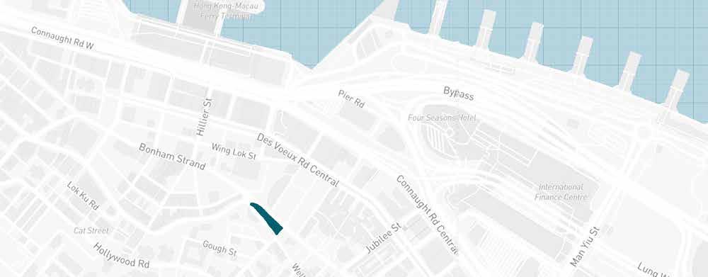
Site:
The project site’s location at the intersection of Wellington St. and Queens Road Central is undeniably one of the most strategic and coveted spots in Hong Kong Island’s central district.

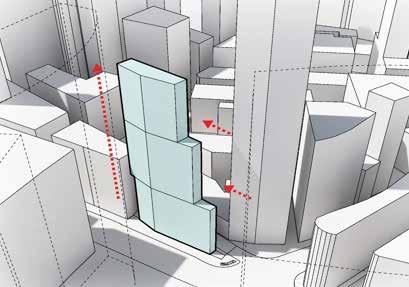
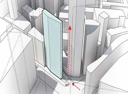

Extrude to the maximum allowed number of stories. (Area:2765.9 sqm, L1-L17: 162.7 sqm)
Creating a series of setbacks allowed as per the local regulation the addition of extra stories, in order to make up for the lost GFA.
The creation of sky gardens and public spaces, also allows the volume to grow higher recovering GFA, increasing the final number of stories.
Massing Study
• Maximise height through extrusion to accommodate more floors and increase the number of stories.


• Incorporate set-backs in accordance with local regulations to add extra stories, compensating for any lost gross floor area.
• Create sky gardens and public spaces to expand the building’s volume, recover the lost GFA, and further increase the number of stories.

• 4 point view by creating vast terrace or balcony that create a conception of leisure in office space.
• Ground level is public space with private lobby for office, the ground space can be used for workshops and expositions.
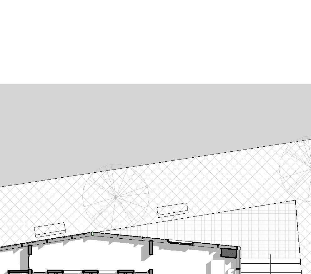
Site Plan Site Plan Coordination Diagrams


1 : 100 Level 0 1
The site plan demonstrates compliance with regulations by providing generous open space around the building. The ground floor is designed as both an entrance lobby for the building and a potential public area. Additionally, the plan includes basement parking spaces to enhance convenience for occupants and visitors.
The illustration shows the integration of different work areas, following a simulated BIM execution plan, to construct a 21-story building. The visual provides a glimpse of a section of the complete 3D rendering of the structure (Level 15 to Level21)
The MEP model was done by another professional, and after the conclusion it was necessary to combine the mep model with structure and architectural model.


FLOOR PLAN LEVEL 16
Fig: 12 Level 16 FLOOR PLAN Scale 1:100
1 1 : 100 L16 SECTION 3
1 1 : 100 L16 SECTION 3
Fig: 13 Level 16 SECTION Scale 1:100
Level 16 Details
The floor plans are a simplified version of detail floor plans from working drawings illustrated using Revit. This condensed representation provides a comprehensive view of the building’s design, aiding stakeholders in understanding the spatial arrangement and functionality. This information can be used to make informed decisions during the construction process, ensuring proper placement of furniture, precise installation of doors/windows, and a clear understanding of the building’s vertical organisation.

FLOOR PLAN LEVEL 18
Fig: 16 Level 16 FLOOR PLAN Scale 1:100
Final Copy 1 1 : 100 L18 SECTION 4
Final Copy 1 1 : 100 L18 SECTION 4
SECTION LEVEL 18
Fig: 17 Level 18 SECTION Scale 1:100
GENERAL NOTES
1. This drawing is Enzyme APD's property and must not be retained, or used without Enzyme APD's authority.
2. All drawings are to be read in conjunction with other relevant drawings specifications of the same and other disciplines.
3. This drawing is not to be scaled. Only written dimensions are to followed. Any discrepancy must be advised to the Architect and the Engineer.
4. All dimensions are metric unless otherwise indicated.
5. The walls are dimensioned to the unfinished face of masonry or unless otherwise noted.
6. Final coordination is the responsibility of the contractor. Any discrepancy must be brought to the attention of the Architect and the Engineer be resolved before commencement of work.
18 Area Plan
Mechanical Engineer
Structural Engineer information can be used to make informed decisions during the construction process, ensuring proper placement of furniture, precise installation of doors/windows, and a clear understanding of the building’s vertical organisation. 47.35 m² NON SELLABLE AREA 31.31 m² SELLABLE AREA Rentable Area NON SELLABLE AREA SELLABLE AREA Electrical Engineer

ABC Design Consultancy 806, Arion Commercial Center, 2-12 Queen's Road West Sheung Wan, Hong Kong AEC Engineering Co 1208, IFC, West Kowloon Hong Kong AEC Engineering Co AEC Engineering Co 1208, IFC, West Kowloon Hong Kong 1208, IFC, West Kowloon ABC AEC AEC AEC Rev Description Level 18 AreaNameLevel m²LIFT LOBBYL 18 m²OFFICE 1L 18 m²ToiletL 18 m²ToiletL 18 m²RoomL 18 m²RoomL 18 m²StaircaseL 18 m²ToiletL 18 m²ToiletL 18 m²OFFICE 2L 18 1 : 200 L 18 6 RENTABLE AREA Level Area L 18 L 18 46 m² L 18 47 m² L 18 31 m²
Firefighting Consultant
CEILING LEGEND
COMPOUND CEILING C1 50MM THK
GULAMB TIMBER SLAT 50X100 MM THK
DROP PENDENT LIGHT
REFLECTED CEILING PLAN- LEVEL 16

The following is RCP for Level 16- Offce 1. Gulamb timber slat of 50x100mm have been used for the ceiling and 2 types of ceiling lighting have been used such as drop pendent light and round flush mount light.

CEILING LEGEND
COMPOUND CEILING C1 50MM THK
GULAMB TIMBER SLAT 50X100 MM THK
DROP PENDENT LIGHT
ROUND FLUSH MOUNT CEILING LIGHT
ROUND FLUSH MOUNT CEILING LIGHT

Structural Plan (Level 16)
The structural arrangement follows a straightforward organizational approach, featuring merely five columns. A spacious central core is incorporated, with walls oriented in various directions. This design choice serves to reduce the number of columns, thereby maximizing the available open space, a crucial factor for office environments.
The secondary core layout comprises two condensed compartments, dedicated to housing all the elevators. The structural documentation operates independently but is coordinated within the architectural files, functioning as a Revit link.
15Concrete-Rectan gular Beam
3L 15Concrete-Rectan gular Beam
6L 16Concrete-Rectan gular Beam

3L 16Concrete-Rectan gular Beam
1L 16Concrete-Rectan gular Beam L 17 ONX_CAP_STR_BEAM_
6L 17Concrete-Rectan gular Beam
3L 17Concrete-Rectan gular Beam
1L 17Concrete-Rectan gular Beam L 18
18Concrete-Rectan gular Beam
Edge Slab Details (Level 16)
Mortar Zone between
Mechanical Engineer
AEC
Structural Engineer
AEC
Detail 1.2- Typical detail for Edge Beam to Slab (Non-Span)Type Local Architect


Rev Description Date 3D ARCHITECTURE 3D 2


Electrical Engineer
ABC AEC
ABC
Firefighting Consultant Interior Designer
1208, IFC, West Kowloon Hong Kong 1208, IFC, West Kowloon Hong Kong ABC
ABC Design Consultancy 806, Arion Commercial Center, 2-12 Queen's Road West Sheung Wan, Hong Kong
AEC Engineering Co 1208, IFC, West Kowloon Hong Kong AEC Engineering Co AEC Engineering Co
ABC Design Consultancy 806, Arion Commercial Center, 2-12 Queen's Road West Sheung Wan, Hong Kong
GENERAL NOTES 1. This drawing is Enzyme APD's property and must not be retained, copied or used without Enzyme APD's authority. 2. All drawings are to be read in conjunction with other relevant drawings and specifications of the same and other disciplines. 3. This drawing is not to be scaled. Only written dimensions are to be followed. Any discrepancy must be advised to the Architect and the Engineer. 4. All dimensions are metric unless otherwise indicated. 5. The walls are dimensioned to the unfinished face of masonry or concrete unless otherwise noted. 6. Final coordination is the responsibility of the contractor. Any discrepancy must be brought to the attention of the Architect and the Engineer and must be resolved before commencement of work. ABC Design Consultancy 806, Arion Commercial Center, 2-12 Queen's Road West
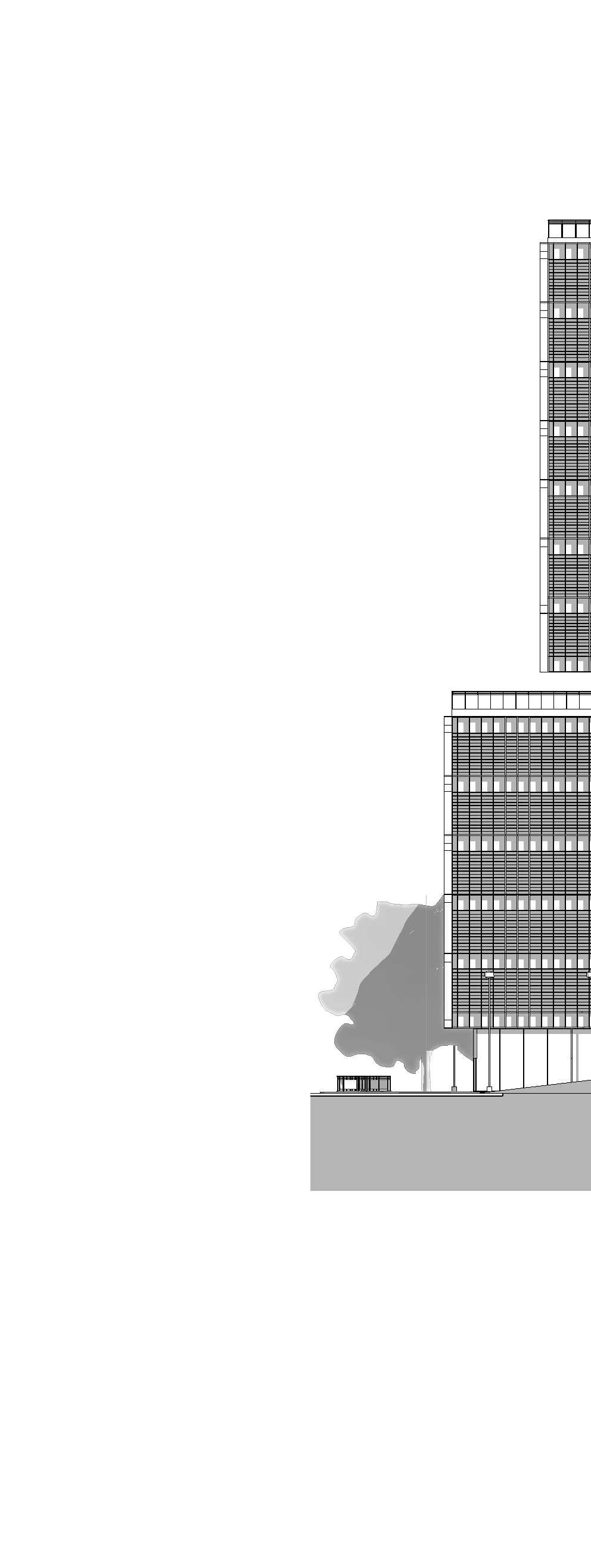
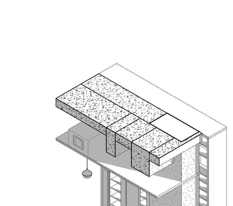
Elevation

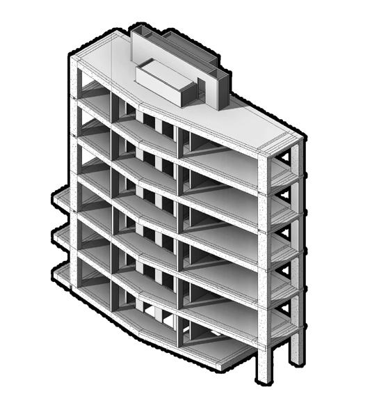
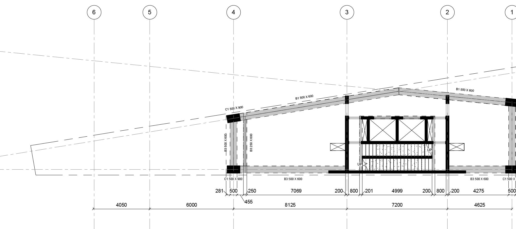
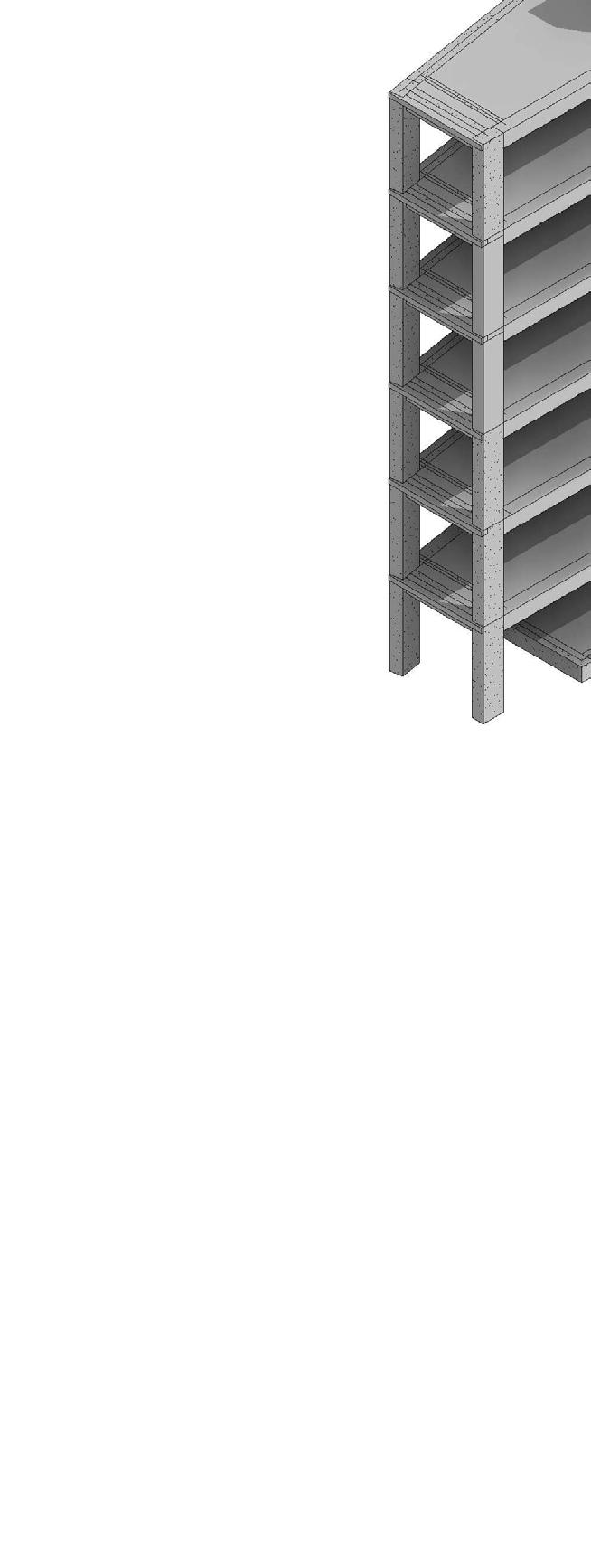
The total height of the project is 82700mm form ground level. there are a total of 21 floors with a basement. The following details are for Zone 3, i.e, Level16- Level 22. The exterior of the facade is cladded with Curtain panels of Glass and Alluminium. The structure has 4 sky gardens that allow the residents to enjoy for a while.


The total height of the project is 82700mm form ground level. there are a total of 21 floors with a basement. The following details are for Zone 3, i.e, Level16- Level 22. The figure here shows the section for the building and a blowup section for level 16-17 showing the different floor types used, different, external facade and the ceiling type. The axonometric shows the external and internal building elements.


L
FAMILY CREATION-DOOR
This section of portfolio shows some of the instances of the family that was created. Various family were created for the project such as Doors, Walls, Floors, Railing, Column, Beams, Staircase etc. Doors were created with parametric values and Fire ratings.

L
L
L
L
115026631
L 19OX_POCKET DOOR_SLIDING_WOOD 586
L 20
L 20LIFT DOOR
L 20OX_0900 X 2100_DOOR_SINGLE LEAF_WOOD900
L 20OX_0900 x 2400_DOOR_SINGLE LEAF_WOOD 900
L 20OX_DOOR_SLIDING_GLASS 115026631
L 20OX_POCKET DOOR_SLIDING_WOOD 586
L 21
L 21OX_0850 x 1950_DOOR_SINGLE LEAF_WOOD 850 19502 Grand total: 78
FAMILY CREATION- WALL
15MM GYPSUM WALL BOARD
15MM GYPSUM WALL BOARD
70MM CELLULOSE FILL
70MM CELLULOSE FILL
15MM GYPSUM WALL BOARD
15MM GYPSUM WALL BOARD
15MM GYPSUM WALL BOARD
70MM CELLULOSE FILL
15MM GYPSUM WALL BOARD
15MM GYPSUM WALL BOARD
15MM GYPSUM WALL BOARD
70MM CELLULOSE FILL
70MM CELLULOSE FILL
15MM GYPSUM WALL BOARD
15MM GYPSUM WALL BOARD
15MM GYPSUM WALL BOARD
70MM CELLULOSE FILL
15MM GYPSUM WALL BOARD
WALL W1 100MM THK. WALL W2 100MM THK.
WALL W1 100MM THK.
WALL W2 100MM THK.
FLOOR FINISH
FLOOR FINISH
WALL W1 100MM THK. WALL W2 100MM THK.
FLOOR FINISH
INSULATION
FAMILY CREATION- FLOOR
INSULATION
CEMENT SCREED
CEMENT SCREED
FLOOR FINISH
INSULATION
CEMENT SCREED
FLOOR F1 150MM THK.
FLOOR F1 150MM THK.
Wall
Wall
FLOOR F1 150MM THK.
Wall
FLOOR FINISH
INSULATION
INSULATION
CEMENT SCREED
CEMENT SCREED
FLOOR FINISH
INSULATION
CEMENT SCREED
FLOOR F2 150MM THK.
FLOOR F2 150MM THK.
15MM GYPSUM WALL BOARD
15MM GYPSUM WALL BOARD
70MM CELLULOSE FILL
70MM CELLULOSE FILL
15MM GYPSUM WALL BOARD
15MM GYPSUM WALL BOARD
15MM GYPSUM WALL BOARD
70MM CELLULOSE FILL
15MM GYPSUM WALL BOARD
WALL W3 200MM THK.
WALL W3 200MM THK.
FLOOR FINISH
WALL W3 200MM THK.
FLOOR FINISH
CEMENT SCREED
CEMENT SCREED
WALL W4
WALL W4
FLOOR FINISH
CEMENT SCREED
WALL W4
FLOOR F3 200MM THK.
FLOOR F3 200MM THK.
FLOOR F3,F4,F5
FLOOR F3,F4,F5
FLOOR F2 150MM THK.
FLOOR F3 200MM THK.
FLOOR F3,F4,F5


RevDescriptionDate


NAVISWORK- CLASH DETECTION
Navisworks clash detection is a valuable process that plays a crucial role in the coordination and successful execution of construction projects. By utilizing the powerful clash detection capabilities of Navisworks software, clashes and conflicts between different building elements, such as architectural, structural, and MEP components, can be identified and addressed. Clash detection involves the automated analysis of models from different disciplines to identify clashes where elements intersect or overlap in the virtual space.


