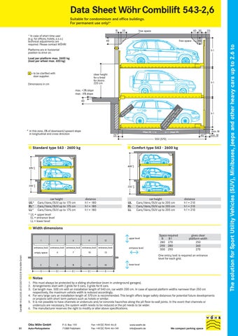
Data Sheet Wöhr Combilift 543-2,6 Suitable for condominium and office buildings. For permanent use only!*
* In case of short time user (e.g. for offices, hotels, a.s.o.) technical adjustments are required. Please contact WÖHR!
35
40 30
free space
40
free space
20
40
X
Platforms are in horizontal position to drive on.
h1
Load per platform max. 2600 kg (load per wheel max. 650 kg)
X = to be clarified with
clear height for a lintel for doors: 220 cm
door supplier. Dimensions in cm
h1
max. +3% slope max. -5% slope 40 re ch co fo ann mm r s e en um l 1 de p 0 x d dr pu 2 ai m plu na p s ge 50 re x 5 ce 0 ss x2 0
e ac sp le on b i i ss ct po r su fo
* in this zone, 0% of downward/upward slope
slope 2%
in longitudinal and cross direction
h1
slope 2%
40*
25*
min.18 min.18
550 (570)
Standard type 543 · 2600 kg
Comfort type 543 · 2600 kg
435 +30
375 +30
200 +30
UL* EL* LL*
230 +30
car height Cars/Vans/SUV up to 175 cm Cars/Vans/SUV up to 175 cm Cars/Vans/SUV up to 175 cm
distance h1 = 180 h1 = 180 h1 = 180
UL EL LL
car height Cars/Vans/SUV up to 205 cm Cars/Vans/SUV up to 205 cm Cars/Vans/SUV up to 205 cm
distance h1 = 210 h1 = 210 h1 = 210
* UL = upper level EL = entrance level LL = lower level
Width dimensions upper level 1
3
6
9
12
entrance/exit entrance/exit entrance/exit entrance/exit entrance/exit
Combilift 543-2,6 | 03.2012 | C027-5223 | © Otto Wöhr GmbH
empty space
7
10
entrance level
gives clear platform width 250 260 270
13
One entry/exit is required on entrance level for each grid. 2
5
8
11
14
B
B1
B1
B1
B
lower level
Notes 1. Pits must always be protected by a sliding shutterdoor (even in underground garages). 2. Arrangements start with 2 grids for 5 cars, 3 grids for 8 cars. 3. Car length max. 500 cm with an installation length of 540 cm, car width 200 cm. In case of special platform widths narrower than 250 cm respectively, the maximum vehicle width is reduced accordingly. 4. For very large cars an installation length of. 570 cm is recommended. This length offers larger safety distances for potential future developments or projects with short term parkers such as hotels or similar. 5. It is not possible to have channels or undercuts and/or concrete haunches along the pit floor-to-wall joints. In the event that channels or undercuts are necessary, the system width needs to be reduced or the pit needs to be wider. 6. The manufacturer reserves the right to modify or alter above specifications.
Otto Wöhr GmbH 01
4
Space required B B1 280 270 290 280 300 290
Auto-Parksysteme
P. O. Box 1151 71288 Friolzheim
Fon +49 [0] 7044 46 -0 Fax +49 [0] 7044 46 -149
www.woehr.de info@woehr.de
We compact parking space
The solution for Sport Utility Vehicles (SUV), Minibuses, Jeeps and other heavy cars up to 2.6 to
15
Doors According EN 14010, the Combilift 543 must be closed with shutterdoors. The door controls are integrated in the overall system. That means: a) The doors are electro-mechanically interlocked b) The doors can only be opened when the selected parking place has reached the entry/exit position c) Any pits are closed in the entrance area
Installation: Behind the building pillars with door offset
Local requirements for electrical doors in respect to technology, maintenance, revision are not subject of our supply, which are according to European standard Door types: Manually operated sliding shutterdoors – for underground garages in galvanised steel – above ground with powder coated metal sheets (RAL 7030) Alternatively, sliding shutterdoors may be supplied with electrical drive.
Installation: Below the lintel between the building pillars
Installation: In front of the building pillars
Section
220
210 220*
210
pit length 550 (570)
X
220*
X
pit length 550 (570)
X
pit length 550 (570)
With installation in front of the pillars, the driving aisle is measured from the door.
X = 25 cm for manually operated sliding shutterdoors X = 35 cm for automatic shutterdoors
Ground plan Marking according to ISO 3864 has to be provided by the purchaser (yellow-black, 10 cm wide)
B3 20
B3 20
* The lintel of 220 cm is absolutely necessary. If differing heights additional fixings are required at additional charge. If no lintel is provided, the gates need to be fitted onto a steel frame (subject to surcharges).
B4
B3
20
B3
20
Space required B3 B4 250 520 260 540 270 560
20
Gives clear platform width 250 260 270
Combilift 543-2,6 | 03.2012 | C027-5223 | © Otto Wöhr GmbH
Floor guide for sliding shutterdoors Floor levelness in door guide range must be conformity with DIN 18202, table 3, line 3.
X
Finished floor acc. to DIN 18353 Floor levelness acc. to DIN 18202, table 3, line 3
Guide rail
Hole depth for dowels approx. 8 cm. Remark: When screed is applied in the door area to obtain floor levelness, the hole depth should be increased by screed thickness (max. 40 mm).
Fixing of guide rail with hexagonal wood screw and plastic dowel S 10
12 02
5
20
Width dimensions and statics All dimensions shown are minimum. Constructional tolerances must be taken into consideration. All dimensions in cm.
Section ( ) dimensions in brackets for longer units
P4
* dimensions for comfort type 158 173* P1 = +80,0 kN 1) P2 = +70,0 kN P3 = +35,0 kN P4 = ± 5,0 kN P5 = ± 2,5 kN P6 = ±30,0 kN P7 = ±15,0 kN
P4 182 197* P4 P5
P5
1)
177 212*
P2 P3
P1 P6 P7
188 223*
all static loadings include the weight of the car
534 (554)
Bearing loads are transmitted by wall plates with min. 30 cm2 surface and to the floor by base plates with min. 350 cm2 surface. Wall and base plates will be fixed by heavy duty anchor bolts to a drilling depth of 10-12cm. When fixing to the waterproof concrete floors chemical anchors are employed (to be advised by Wöhr). Base plate thickness minimum 18 cm. Rear wall and base plate must be formed of concrete and must have a flat surface without protrusions. Concrete quality according to the static requirements of the building, but for the dowel fastening we require a concrete quality of min. C20/25. The specified lengths to the support points are mean values. Please contact Wöhr Agent for exact positions for any variations on the standard units. Please contact Wöhr Agent for clarify the door widths/widths of columns. Grid width of 270 /280/290 cm must be observed.
Ground plan B2
B1
B1
B1
B1
B2
P7
P1
P6
P1
P6
P1
P6
P1
P6
P1
P7
P5
P4
P5
P4
P5
P4
P5
P4
P5
P4
P5
544 (564) 550 (570)
P5
P5
P5
P5
P5
P5
P3
P2
P2
P2
P2
P3
B1
B3 20
B1
B3 20
B
B1
B3 20
B 280 290 300
B4 20
Space required B1 B2 B3 270 145 250 280 150 260 290 155 270
20
B4 520 540 560
gives clear platform width 250 260 270
Notice: If the width of the pillars is more than 20 cm, than the width of the drive through will be reduced accordingly to the above mentioned width dimensions. In order to avoid this we recommend to extend the measures between the pillars (B3 and B4) accordingly. Please contact WÖHR.
Minimum driveway width according to local requirements
Combilift 543-2,6 | 03.2012 | C027-5223 | © Otto Wöhr GmbH
B
03
Hydraulic power packs
Numbering of the parking spaces e.g. in a wall recess. Dimensions: length = 100 cm height = 140 cm depth = 35 cm
client. In compliance with the DIN EN 60204 standard provisions, all systems must be connected directly on site with an earthed equipotential bonding. The leadout connection must be at a 10 m distance!
Switch cabinet
General product information space is above the lower level platform to be raised, or below the upper floor platform to be lowered. This movement is initiated automatically when the desired place is selected via keyboard.
Hotel garage
LL
2
3
6
9 12
4
7 10 13
5
8 11 14
3. The numbering for each system starts with 1 as above. 4. Different numbering of parking spaces is possible at extra cost (software changes are necessary).
Illumination
Free spaces Special drawings for free spaces to accommodate air ducts or other pipes can be requested at Wöhr Agent!
Railings If walkways are arranged directly to the side or behind the systems, railings have to be provided by client acc. to local requirements, height min. 200 cm – this is applicable during the construction phase too.
Drainage To prevent hazards for the ground water, we recommend giving the pit floor an oil-resistant coating as a means of protecting the environment. If this is to be connected to the sewage system, it is advisable to provide oil and/or petrol seperators.
We recommend providing gutter in the pit centre and connecting the gutter either to a gully or a drainage pit 50 x 50 x 20 cm. If the pump sump is not accessible for manual drainage, the client must provide a pump on site to empty the pump sump. Lateral slope only within the gutter.
Maintenance Regular maintenance by qualified personnel can be provided by means of an Annual Service Contract.
Protection against corrosion
If used by hotel guests, the installation requires special planning and construction. Please ask for details.
Noise protection Basis is the German DIN 4109 “Noise protection in buildings”. With the following conditions required 30 dB (A) in rooms can be provided: – noise protection package from our accessory – insulation figure of the construction of min. R’w = 57dB – walls which are bordering the parking systems must be done as single wall and deflection resistant with min. m’= 300 kg/m2 – solid ceiling above the parking systems with min. m’= 400 kg/m2
1
Illumination has to be considered acc. to local requirements by client.
1. Main switch is installed well accessible at driveway in a height of 160 cm to 190 cm. 2. The switch cabinet must be installed visible and near by the system. Area for installation has to be provided by the client. The size of the switch cabinet is 80 x 110 x 21 cm. 3. The wall opening of 15 cm diameter is required between the switch cabinet and the system itself. Please contact Wöhr Agent to clarify. 4. The control is designed to operate between +5° and +40° C. Atmospheric Humidity: 50% at +40°C. If the local circumstances differ from the above please contact Wöhr (if necessary, the switch cabinet has to be provided with a heating). 5. If the system is installed outside the switch cabinet needs to be inside a sun-/water-/wind proof box. In front of the switch cabinet an area of 100 cm is required to work.
The entrance level parking place row has one place less than the upper and lower level. This empty space always stays on entrance floor level. The platforms at the entrance floor level are shifted sideways by one space so that the empty
UL EL
Electrical data Main electrical supply 230/400V, 50 Hz, 3 phase. Power consumption 3.0 kW. Fuse or automatic circuitbreaker 3 x16A slow blow acc. to DIN VDE 0100 p. 430 and main supply line 5 x 2,5 mm2 to the switch cabinet, provided by
1. The empty space of the Combilift is always on the left in the entrance level. 2. The numbering is as follows:
At differing constructional conditions additional sound absorbing measures are necessary. The best results are reached by separated sole plates from the construction. Increased noise protection: If increased noise protection must be provided planning has to be confirmed on a project basis by Wöhr (further building measures are required).
Temperature The installation is designed to operate between +5°and +40°C. Atmospheric Humidity: 50% at +40°C. If the local circumstances differ from the above please contact Wöhr.
Independent of a maintenance workings has to be carried out acc. to Wöhr Cleaning and Maintenance Instruction regularly. Clean up galvanized parts and platforms of dirt and road salt as well as other pollution (corrosion danger)! Pit must be always ventilated and dearated well.
Dimensions All dimensions shown are minimum. Construction tolerances must be taken into consideration. All dimensions in cm.
Clearance profile (standard saloon/estate car) 10
40
60
8
162
40
48
150* 46 (175*) (205*) 275
22 38
14
60 120
max. 290 500
90
* The total car height includes roof rail and antenna fixture and must not exceed the mentioned max. height dimension.
Notes We recommend providing wiring conduits leading to operating panels, particularly in aboveground garages.
The wiring conduits should placed 120 cm above entrance level in a support in the middle of the area.
Combilift 543-2,6 | 03.2012 | C027-5223 | © Otto Wöhr GmbH
For the accommodation of the hydraulic power packs an additional space is required which will be determined during the verifications of the drawings,
04