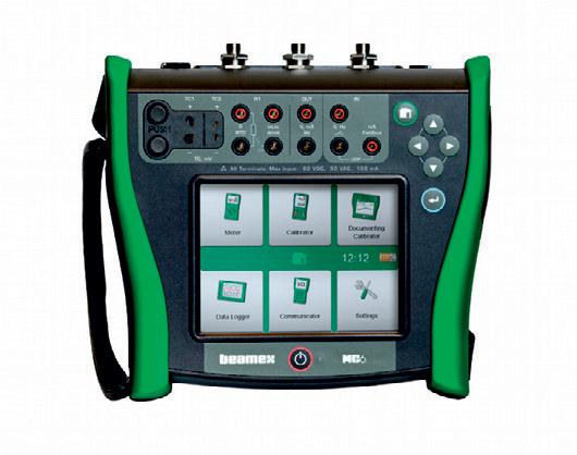
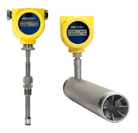
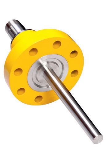
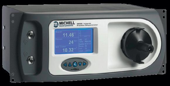
Instrumentation and calibration equipment from

Instrumentation and calibration equipment from
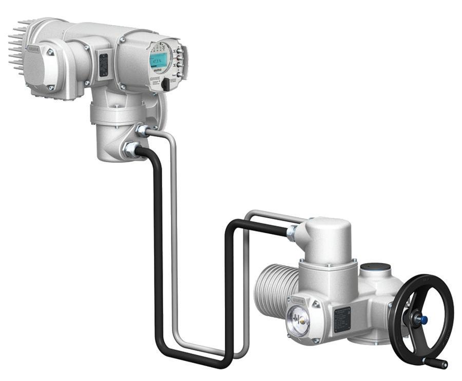
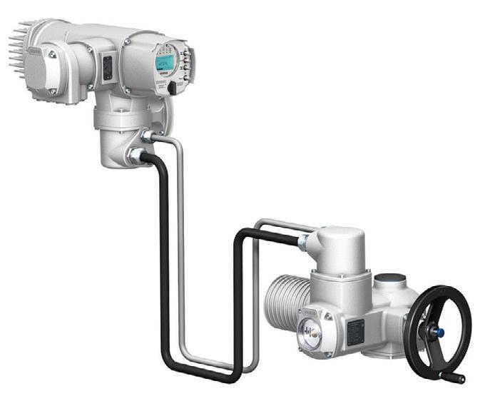
For several decades, AUMA actuators have proved their reliability in automating sluice gates, butterfly valves and gates in weirs, fish ladders, locks and hydro-power plants.
AUMA’S comprehensive portfolio covers torques ranging from 10 Nm to 675,000 Nm offering homogenous automation schemes throughout the plant: from simple OPEN-CLOSE applications to level control using an integral PID controller.
www.auma.com
78 Dickson Avenue, Artarmon NSW 2064
Telephone: 02 8437 4300
Email: info@barron.com.au
BARRON GJM PTY LTD ABN 90 003 560 076


AMS Instrumentation & Calibration has a long history of supplying industrial instrumentation (flow, pressure, level, temperature, analytical and ancillary equipment) and calibration equipment to all industries, government departments and public utilities. AMS is proud to have developed these relationships over many years and will continue to do so while building new relationships as they arise. AMS’ proven track record over the years is testimony to its commitment to quality sales and service.
The company, originally established in 1973, has its head office in Melbourne, as well as offices in NSW, WA and Queensland, and supplies many products to New Zealand, Papua New Guinea and the Pacific Region. The company has seen tremendous growth since its formation. In May 2023, AMS further expanded with the purchase of Streat Control in New Zealand. This transition will further expand the range of high-quality products and services available across various industries, leveraging strong relationships with leading manufacturers to provide innovative and precise solutions tailored to clients’ needs both in Australia and New Zealand.
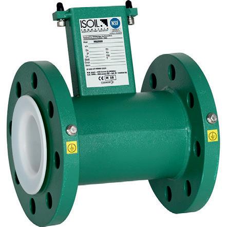
Recent development has also seen the exclusive appointment of AMS as exclusive distributor of ISOIL Automatica, further enhancing the company’s product portfolio.
AMS has been very proud to have serviced all industries over the years and looks forward to continuing that service.





Decarbonisation, cybersecurity and plant efficiency are possibly the three hottest topics of discussion in industry today. And when it comes to efficiency, it is not just the process itself that needs to be focused on, but also the tools and methodologies used by engineers in the design and management of the plant.
Keeping up with the pace of change means making engineering practices as efficient as possible: and a productivity and quality gap that many industrial organisations have had to quietly acknowledge is the state of software engineering practice in operational environments. There is a need to chart a path towards modernisation — drawing on contemporary tools, disciplined version control, and collaborative practices already standard in enterprise IT.
The same goes for decarbonisation: there are many worthy projects that can be embarked on to reduce carbon emissions, but they often forget the obvious improvements that can be made with existing plant infrastructure. One such often-overlooked area is the efficiency of compressed air systems — among the largest consumers of electrical energy on any plant. There are a number of activities and techniques that can be applied to existing air infrastructure for little cost that can deliver significant carbon and cost reductions — frequently without the scale of capital commitment required by more headline-grabbing projects.
And then there is the increasing problem of cybersecurity. In this issue we have an article that helps to cuts through the noise surrounding zero trust, applying the model specifically to operational technology environments.
Finally, we examine a common but underappreciated consequence of variable speed drive adoption: accelerated motor bearing wear. Our tech tips article sets out practical mitigation strategies that allow engineers to capture efficiency benefits without compromising equipment longevity.
As usual, more content can be found on processonline.com.au, and by subscribing to our bi-weekly email newsletter.
Glenn Johnson Editor pt@wfmedia.com.au


The federal government has announced that Western Australian resources company Arafura Rare Earths will ramp up rare earths mining with support through the $1.2 billion Critical Minerals Strategic Reserve.
The company has announced a final investment decision on its Nolans rare earths project in the Northern Territory, and the Government has provided a non-binding commitment to secure 500 tonnes of rare earths from the project through the Reserve. Arafura will now move to commence construction on the project, 135 km north of Alice Springs, which will mine and process rare earths.
The Nolans project will produce neodymiumpraseodymium oxide, or NdPr, a critical input for high-performance permanent magnets used in electric vehicles, wind turbines, advanced manufacturing and defence technologies.
Once operational, the Nolans Project is projected to supply approximately 4-5% of global rare-earth demand, making significant inroads to building an alternative supply chain in products that have been the subject of supply bans and disruptions.
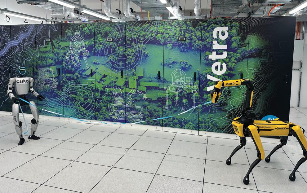
CSIRO has built new infrastructure anmed Vetra that brings powerful AI processing much closer to where data is created — right alongside the robots and sensors that rely on it.
Unlike traditional, remote cloud-based data infrastructure, Vetra provides super-fast, onsite processing close, or on the ‘edge’ to where data is generated. This allows robots and sensing systems to respond faster, learn continuously and operate more safely in complex physical environments.
Liming Zhu, Director of CSIRO’s Data61, said Vetra delivers sovereign, trusted AI computing at the edge, close in physical proximity to where data is generated by robots and sensing systems.
“Vetra enables real-time physical AI research by bringing high performance computing to the edge, where proximity to data allows systems to respond, learn and operate safely in complex environments in ways that are not possible with cloud only or distant data centre approaches,” Zhu said.
Vetra sits alongside Australia’s largest robotics research facility, allowing AI systems to learn directly from real-world testing rather than simulations alone.
The WA Government has opened expressions of interest (EOIs) for companies with an international market to establish a presence in Western Australia around the building of an advanced defence manufacturing hub in Western Australia. The initiative is aimed at companies with cutting-edge capability and expertise across defence manufacturing, industrial systems and enabling technologies.
The proposal will explore the development of a large-scale co-located industrial footprint that connects advanced manufacturing, innovation, logistics and supply chains within a single strategic location.
The government says the opportunity spans a wide range of industries, including precision manufacturing, advanced materials, aerospace and autonomous systems, energetics, space technologies and other high-end capabilities critical to modern defence.
Expressions of Interest will close on 8 July.


To keep up with increasing complexity, the programming practices used in industry need to be modernised with the latest tools and techniques.
The last decade or so has seen a sharp increase in the demands placed on industrial control systems. This is due in part to the higher levels of automation needed to make products efficiently; but industry is also having to fulfil ever greater and more diverse customer requests.
These increases in demands have led to what seems an exponential rise in the complexity of programs used by industrial control systems — a trend that seems certain to continue well into the future. The overall value of a control system has moved away from its hardware, and is now heavily weighted towards its software, which contains the intellectual property (IP) of the overall system.
Software development therefore needs to be carefully controlled to prevent programs becoming unwieldly, difficult to maintain and highly time‑consuming to fault‑find. If not kept in check, program management will become ever more expensive and burdensome for industry.
Fortunately, more attention is being paid to the software engineering practices used by industry. This will become ever more important as companies seek to digitise their operations. It will also help avoid cost blow‑outs for software projects.
Industry has long recognised the trend towards ever greater complexity and the ramifications it has for programming. PLCopen is one organisation specifically established to help in this process. Its stated aim is to enhance the quality of industrial software and thereby improve the overall efficiency of industry.
Being vendor neutral, PLCopen seeks to collaborate with as many vendors as possible, across a wide range of industries. It creates vendor working groups with the goal of creating standards for industry. The process is long, with many requests for comments (RFCs) received from vendors, but the final product shows the benefit of such collective input.
In the early days, PLCopen promoted the use of the IEC 61131‑3 PLC programming standard. Since then, it has more recently branched out into producing standards for other aspects of industrial control such as motion, safety, communications (mainly OPC UA) and data exchange. It also provides training and certification services for vendors to publicise their level of compliance to these standards.
The use of such standards has undoubtedly increased the quality of software used in industry; it has also helped programmers become more efficient in their automation projects.

For many years, industrial programmers have had to purchase a development package for their controllers and install it onto their local computer. This computer was usually located close to the controller so that a physical connection could be made to it.
Creating programs in this way almost always restricted program development to a single user, working on a solitary computer. It also meant the programmer was solely responsible for procuring and maintaining the computer hardware, as well as generating backups of the program. They were responsible for installing updates (to both the operating system and development package) and for ensuring the integrity of the system by protecting against malware.
Much effort was required of this one programmer — in areas they were not necessarily expert in. Nevertheless, this model has worked reasonably well over many years and continues to be used today. But apart from the extra demands placed on the programmer, the one aspect that’s becoming increasingly important is the ability to support multiple programmers on the same project. Due to the growing complexity of programs and the sheer amount of code that needs to be written and tested, projects are increasingly drawing on expertise from different areas, necessitating collaboration from numerous programmers.
It’s become clear that to successfully navigate the larger, more complex programs required of modern applications, the programming practices used by industry will need to be modernised.
To improve programming efficiency, industry should really adopt more of the methodology and techniques commonly used in mainstream IT. For example, Visual Studio is a popular development environment used by IT: it is very adept at handling large programs and supports some very useful facilities that make programming manageable and easy to fault‑find.
The first PLCs were designed to replace hard‑wired relay circuits, and thus only supported the ladder diagram programming language. While it is still the preferred language for solving Boolean
logic type problems, its overuse will cause a phenomenon called ‘code bloat’, where PLC programs are far longer and more complicated than they need to be. However, the use of structured text language will prevent programs from becoming overly convoluted, particularly when an application requires heavy mathematical calculations.
Object‑oriented programming (OOP) is another example of a programming paradigm that’s been available for decades to the IT community but is still not supported by most industrial vendors. This is despite OOP’s inclusion into the third edition of the IEC 61131‑3 programming standard in 2013.
The way OOP organises programs around objects with data and code is radically different from the logic and functions approach of traditional industrial programming. Certain applications lend themselves very well to OOP and its use greatly simplifies programming. Moreover, without OOP, these applications would become far less efficient and more difficult to manage.
One of the more recent innovations in software engineering has been the adoption of cloud‑based services. The cloud, with its virtually unlimited storage capacity, very scalable infrastructure and large array of facilities, has become highly attractive to businesses. It’s also being used extensively by IT departments.
Automation suppliers have similarly been integrating the cloud into industry and using it in areas like IoT for ‘big data’ collection. Using existing internet infrastructure, the cloud can similarly add value to industrial programming environments and can add features that would otherwise be very difficult to implement.
So what exactly is cloud‑based engineering and how can it be applied? More importantly, how can it help us improve what we do?
With cloud based engineering, the whole development suite — together with all its tools — resides not on a local computer but in the cloud. The entire programming environment is called a ‘virtual machine’ because, while it exists in cyberspace, as far
as the programmer is concerned it runs as if it’s installed on the developer’s local machine. Every controller is given its own instance of a virtual machine image in the cloud. Programmers need only login to a portal via a standard web browser on a local device to access it; no special software needs to be loaded. The physical industrial controller on the factory floor is also tunnelled to the cloud via a secure transport channel and linked to the virtual machine to enable program deployment.
One advantage of using the cloud in this way is that it provides true platform independence. Programmers aren’t restricted to just desktop computers: they can use tablets, mobile phones or any other internet‑enabled device. The internet affords complete location independence, meaning programmers and controllers can be anywhere in the world. This alleviates the need for programmers to be physically present onsite.
Perhaps the most significant advantage of cloud‑based engineering is the lifting of the burden on the programmer having to provide the computing resources. With the cloud, it’s the vendor who’s responsible for supplying all the computing hardware and software, as well as its maintenance and the installation of updates. File handling is also performed by the cloud provider; programmers do not need to be concerned with backups or malware.
Another advantage is the elimination of having separate software versions for different firmware editions. In the cloud, every firmware revision is supported, and each will have their own virtual machine. In this way, programming software always matches the controller’s hardware and firmware revision.
Version control (ie, the handling of different revisions of the same program) can be handled in the cloud by seamlessly integrating established systems such as Git. Git is arguably the most used versioning system and its branching and merging facilities are ideal for collaborative work between multiple programmers.
Cloud‑based engineering undoubtedly improves the productivity of the

programming team. It does this by streamlining their work and allowing them to concentrate on their core task of programming, rather than peripheral issues such as file management.
However, security remains a significant concern for some users, who need to be highly protective of their IP, as it’s what gives them their market advantage. For this reason, some web‑based services are hosted locally, rather than in the cloud, where the location of the data is often unknown. While some cloud providers counter this by specifically guaranteeing the final location of the data by country, a hybrid cloud system remains a viable alternative. This is where the cloud is used for general data and services, and a locally‑hosted cloud stores the sensitive elements.
Cloud‑based computing is essentially a software as a service (SaaS) offering. Despite the advantages of SaaS, take up in the
industrial space has heretofore been slow — the main reason being the lack of support from industrial vendors. This placed the onus of creating virtual machines in the cloud and connections to the hardware onto the programmer. These tasks are difficult to implement without expert knowledge.
To help overcome this roadblock, hardware vendors are starting to rent out cloud‑based engineering services to their programmers. They have created web‑based portals for users to login to, dashboards into virtual machines, and connection handles for real controller hardware. The portal can also provide tutorial support and guidance documentation.
Setting up a new cloud instance only takes a few minutes, with many of the functions automated. In future, vendors will be able to extract operational data through the same channels and can add value to their offerings by including integrated analytics, predictive maintenance and much more.
While still embryonic, offerings for
TO IMPROVE PROGRAMMING EFFICIENCY, INDUSTRY SHOULD REALLY ADOPT MORE OF THE METHODOLOGY AND TECHNIQUES COMMONLY USED IN MAINSTREAM IT.
cloud‑based services are starting to appear, albeit slowly. And with the integration of AI into programming, it seems certain the cloud will be increasingly used in industrial software engineering.
*Harry Mulder is the Principal Automation Engineer at Beckhoff Automation. He has been involved in industrial automation for over 30 years and is fascinated by how new innovations keep affecting the direction of the industry. He really enjoys the practical element of his job, where he has a chance to get his hands dirty!
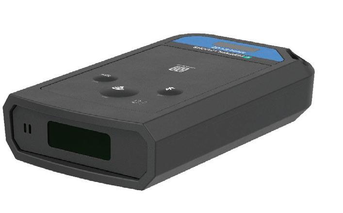
The Ident Ex 02 is a pocket scanner designed for safe mobile data capture in Zone 1/21 and Div. 1 hazardous environments.
Pepperl+Fuchs (Aust) Pty Ltd
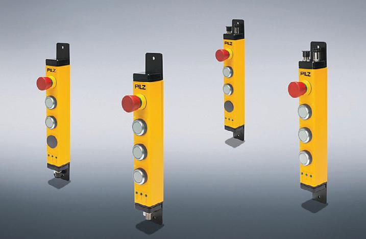
Built on the open, standardised IO Link Safety protocol, the PITgatebox IOLS simplifies both commissioning and maintenance.
Pilz Australia Industrial Automation LP
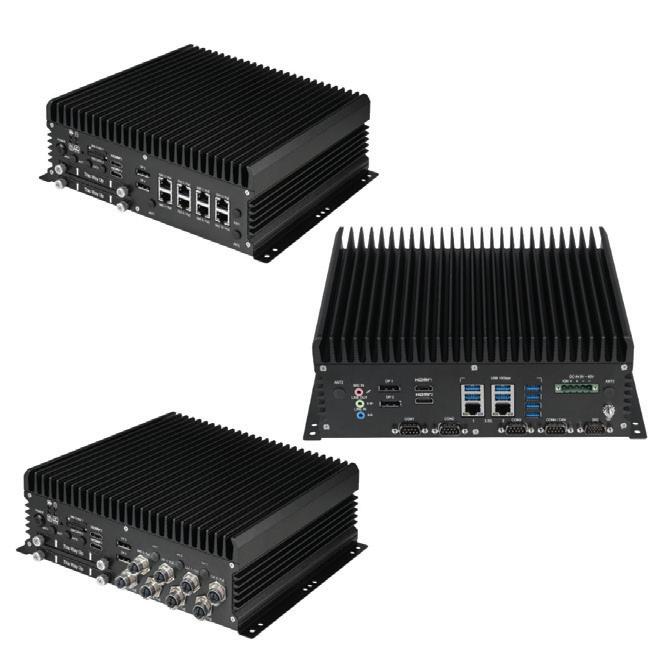
The ABOX 5220 is an advanced AI GPU edge computer engineered for demanding industrial and in vehicle environments.
Backplane Systems Technology Pty Ltd
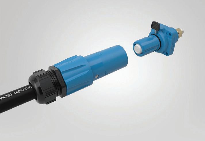
The EPIC POWERLOCK from LAPP has a mechanism with a fully integrated slider, which allows release without the need for special tools.
Treotham Automation Pty Ltd

Which checks have already been carried out on the machine?

Are my employees su ciently qualified?

Where do I find the safety validation documents?


Do all the protective measures comply with the standards?

How do I ensure that I meet my obligation to provide documentary evidence?

With MYZEL, you don’t need to implement everything at once. myCore provides an easy entry point, giving you immediate visibility and control over your machine and employee data. When requirements increase, you can seamlessly expand the platform with dedicated workflows for safe machine design, operation, and access control - exactly when you need them.
mySafeDesign –Safe machine design

mySafeOperation –Safe machine operation
myAccessControl –Secure access management
Risk assessments including AI-supported identification of risks via image recognition Validation of new machinery
Templates for statutory inspection obligations, maintenance and recurring validations for existing machinery
OT security for plant and machinery Management of employee authorisations and qualifications



The HYDAC FCU 1000 Series fluid control unit is a rugged and portable solution for short term, onsite measurement of particle contamination, water saturation and fluid temperature in hydraulic systems and diesel fuels.
Designed for service, maintenance and diagnostics, the FCU 1000 features an integrated pump and hoses that allow easy sampling from control circuits, pressure lines and unpressurised tanks with minimal set up. The unit provides cleanliness ratings in accordance with ISO, SAE and NAS standards, and stores timestamped data that can be quickly downloaded to a PC or analysed using HYDAC’s FluMoS software.
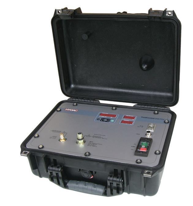
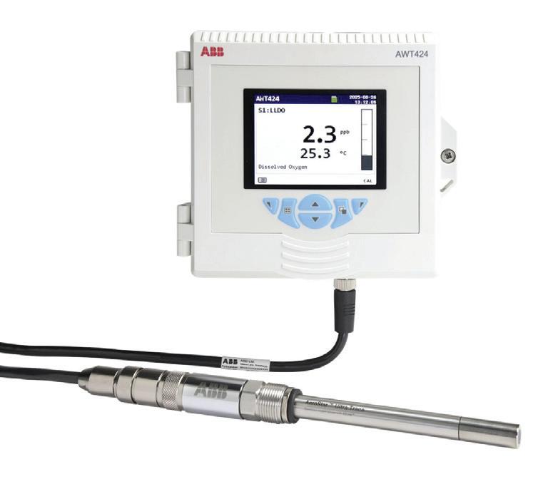
ABB has launched the AeroStar family of dissolved oxygen sensors and the AWT424 transmitter.
Compared to traditional electrochemical sensors that can require frequent sensor replacement, calibration and maintenance, AeroStar is designed to provide stable, accurate water quality measurement with minimal maintenance.
Compact, the FCU 1000 enables technicians to gain fast and accurate insights into fluid condition, helping to optimise uptime and prevent costly failures.
HYDAC International www.hydac.com.au
Engineered for applications in the power, process steam, semiconductor, and food and beverage industries, where even trace levels of dissolved oxygen can compromise performance or cause corrosion, the AeroStar ULTRA measures down to four parts per billion, while AeroStar ULTRA TRACE delivers measurement capability below one part per billion (ppb). The luminescence quenching optical design is said to offer stability and precision, with a fast response time and extended sensor cap life of up to two years — reducing maintenance by as much as 70% compared to traditional electrochemical devices.
The AeroStar sensors connect via ABB’s EZLink digital platform with the AWT424 transmitter and offer predictive maintenance alerts through the EZLink Connect App.
Engineered for excellence, trusted by industry

• Australian standards compliant.
• Data processing and process control
• Instrument-to-instrument connections
• Protects signals from interference caused by other electrical circuits
• Connects electrical measuring devices to instrument panels
• Links electrical sensing devices to control cabinets
• Transmits signals in remote control, indication, telemetering, monitoring, and analysis systems

The next generation AWT424 transmitter is designed to simplify and unify water measurement, allowing operators to connect and control up to four sensors simultaneously, offering a complete view of water quality, including parameters like pH/ORP, conductivity, turbidity, chlorine and dissolved oxygen.
With its modular design, the AWT424 enables operators to add and change sensors and communication modules. A full colour TFT display and Bluetooth connectivity make real time data accessible through ABB’s EZLink Connect App. The AWT424 also adds Modbus TCP communications, further simplifying its integration into plant control systems.
ABB Australia Pty Ltd www.abbaustralia.com.au
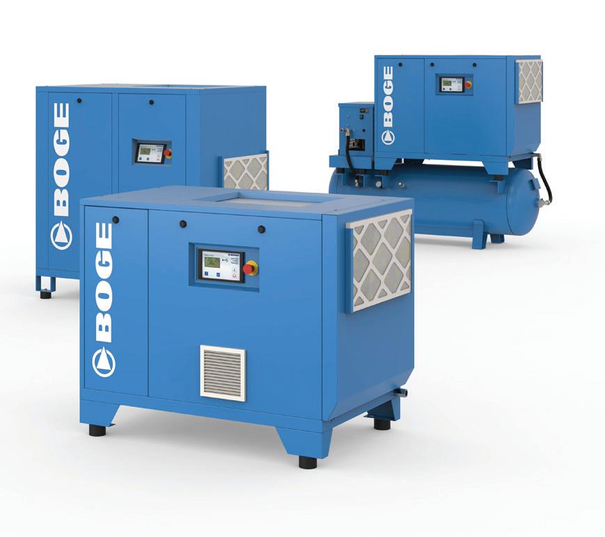
The Boge E series oil lubricated screw compressor is aimed at users who require solid basic equipment without extended premium functions and who depend on compressed air in daily operations. At the heart of the series is a low maintenance and durable airend, combined with an efficient drive motor and the BOGE GM drive system, which is designed to ensure constant belt tension in every operating phase.
The design relies on established standard components so that maintenance and the supply of spare parts is easy and cost effective. Another feature of the series is the low temperature difference between the ambient air and compressed air at the outlet, which is made possible by generously sized coolers. A low outlet temperature forms a good basis for subsequent effective treatment of the compressed air.
The E series comprises various models with different housing sizes from 4 to 30 kW and maximum pressures of 7.5, 10 and 13 bar, including versions with optional frequency control for compressed air generation adapted to requirements. For applications in the lower output range up to 15 kW, complete systems with integrated dryer and compressed air receiver are also available — suitable for companies that require a compact, central compressed air system that is ready for immediate use.
Boge Compressors (Australia) Pty Ltd www.boge.net.au
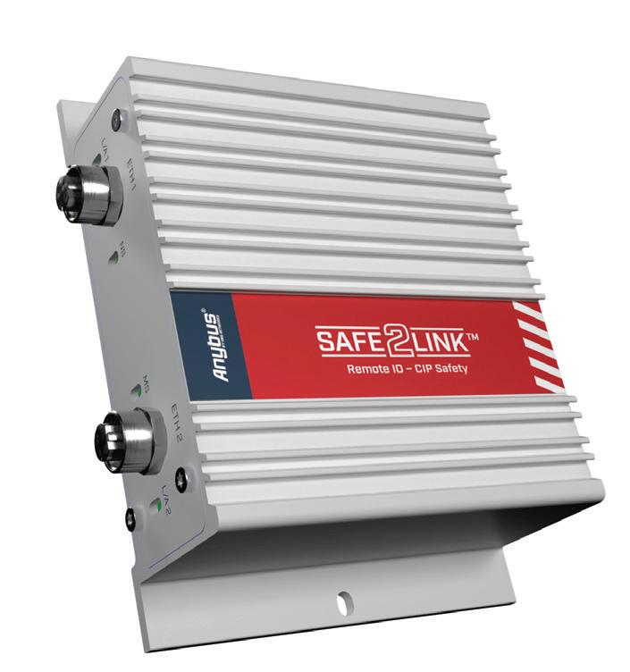
HMS Networks has announced the release of the Anybus Safe2Link Remote IO CS, a rugged, type approved I/O device designed to simplify the integration of functional safety into AGVs, AMRs and other mobile machines. With TÜV certified safety functions and support for CIP Safety over EtherNet/IP, the Anybus Safe2Link Remote IO CS is designed to provide a simpler path to compliance with ISO 3691 4 and the upcoming EU Machinery Regulation 2023/1230.
The Anybus Safe2Link Remote IO CS mounts directly on the machine, enabling system integrators and machine builders to add a safe remote stop and manage local or remote safety signals without custom hardware design. Since it connects with existing local safety logic, system integrators can implement the same safety functions across AGV/AMR platforms from different suppliers. This simplifies integration and reduces the effort required for the recertification of functions such as safe remote stop.
Advanced safety features such as SafeBound (fast local and slow remote safe reaction) and SS1 t (controlled safe stop) allow machines to react predictably, protecting both people and equipment.
With certification up to SIL 3 (IEC 61508) and PLe/Cat. 4 (ISO 13849 1), the Safe2Link Remote IO CS is type approved and ready to deploy. Its rugged IP54 enclosure, dual M12 Ethernet connectors and straightforward D Sub I/O interface make it suitable for industrial environments.
HMS Industrial Networks hms-networks.com
Byron Raal*
Why process engineers should look at their compressed air system before their next capital decarbonisation submission.
Most facility decarbonisation plans tend to favour visible interventions like rooftop solar, battery storage and process electrification. All these are of course worthy paths to follow, but they are costly interventions, and if there are existing energy inefficiencies in the plant, they will do nothing for them.
For many plants, inefficiencies in compressed air systems are a significant source of wasted energy, but they can be significantly reduced for far less outlay.
Most Australian process plants can cut compressed air energy consumption by 25–40% inside 12 months with modest capital outlay, and the business case reads very differently once the correct commercial and industrial electricity rate is applied.
Compressed air typically accounts for around 10% of industrial electricity consumption on a general manufacturing site and up to 30% on air intensive process lines, yet it rarely appears on facility level decarbonisation plans because the losses do not sit under a single line item. Leaks, artificial demand, pressure band overshoot, and part load inefficiency all bleed energy quietly, and each one responds to a different lever.
This article walks through the three highest return interventions in sequence, with calculations grounded in the 2025–26 Australian C&I tariff environment.
All worked examples below use $0.27 per kWh as a representative 2025–26 Australian commercial and industrial rate inclusive of network, retail and environmental charges. Actual rates vary by state, retailer, contract and demand profile.
An energy audit on a compressed air system is not exotic instrumentation work. Power meters on the compressor feed, pressure transducers at the header, flow measurement (where it can be fitted) at three or four representative points of use, and an out of hours leak survey with an ultrasonic detector are enough to produce a defensible baseline.
Done well, the audit will quantify four problems that show up repeatedly on Australian process plants:
1. Artificial demand
2. Pressure creep
3. Leaks
4. Part load inefficiency.
Artificial demand is the result of not tracking real use. Many systems were sized for a production peak that no longer exists, and the compressor still cycles to deliver that capacity.
Similarly, pressure creep occurs when, for example, a system set at 8–8.5 bar when it was commissioned a decade ago, but often feeds end use equipment that only needs 6–6.5 bar now.
Leaks come third. A 3 mm hole at 7 bar pressure leaks approximately 7.3 litres per second (0.44 m3/min) of free air delivery.
At a typical specific power of 7.5 kW per cubic metre per minute for a modern 7 bar rotary screw compressor (approximately 0.12 kWh per cubic metre of free air delivered), that single leak draws around 3.3 kW continuously. If you run that compressor for 4000 hours per year on that one leak (a conservative estimate accounting for seasonal variation and part load periods) that single air leak costs close to $3560 dollars annually. A plant with five such leaks is haemorrhaging around $18,000 dollars per year before anyone has walked the shop floor with a soapy spray bottle.
Part load inefficiency is the fourth major issue. Fixed speed compressors running on load–unload cycles waste a substantial share
of input power every time they blow down. An air audit rarely surprises experienced operators. What it does, though, is convert suspicion into quantified Capex ready findings, which is what a process engineer needs before a decarbonisation submission will get past the CFO.
Pressure reduction is the fastest and cheapest decarbonisation lever available, and the relationship between energy savings and pressure reduction is close to linear at industrial operating ranges: roughly 7% of compressor electrical input is saved for every 1 bar reduction in discharge pressure.
If you drop system pressure by 1 bar on a 45 kW rotary screw running two shifts, 16 hours per day, 260 operating days per year, then the annual saving lands at $3538. Drop it by 1.5 bar and that climbs to $5307.
The Capex cost is zero for the reduction itself, though point of use regulators and flow controllers are often worth fitting to let individual circuits run at their minimum required pressure.
The method is methodical rather than clever. Reduce the discharge pressure setpoint in 0.5 bar steps over days or weeks, and monitor actuator response, cylinder cycle times, air tool performance and the pressure at the furthest point of use. The system design target is a total
system pressure drop of 0.1–0.3 bar from the receiver to the end use. If the drop is larger than that, the piping, filters or drain traps are the real bottleneck and should be addressed before the headline setpoint is pushed lower.
Most plants find that 1–1.5 bar of genuine headroom exists. Capturing savings from that headroom requires no outside consultant, no capital submission and no new equipment.
Fixed speed compressors match a fixed motor speed to a highly variable demand. When demand drops below compressor
MOST AUSTRALIAN PROCESS PLANTS CAN CUT COMPRESSED AIR ENERGY CONSUMPTION BY 25–40% INSIDE 12 MONTHS WITH MODEST CAPITAL OUTLAY
capacity the unit unloads, and unloading still draws roughly 30% of loaded power while producing no useful air. Variable speed drive compressors modulate motor speed to track demand, which collapses that unload waste.
For a 45 kW compressor running two shifts in a process site with variable demand, a representative real world outcome is 20% energy savings from a VSD retrofit. Running 16 hours per day, 260 days per year, at $0.27 per kWh, the baseline electricity cost for that compressor is $50,544 dollars per year, so a 20% reduction will save $10,109 dollars per year.
A VSD retrofit on a 45 kW rotary screw compressor typically installs for $14,000 to $20,000 in Australia, which gives a payback window of 16–24 months. After that, the facility banks around $10,000 dollars per year in pure energy savings for the remaining life of the compressor package.
Two conditions matter though:
1. There needs to be variable demand:
A retrofit only makes sense on a variable demand duty cycle. A plant running 24/7 at a flat load will see smaller percentage savings, because the unload losses the VSD eliminates are already small.
2. Planned replacement vs retrofit:
A VSD compressor brought in during planned replacement, rather than as a retrofit, integrates far more cleanly and typically arrives with heat recovery interfaces already fitted.
Rotary screw compressors in flat single shift duty typically reach 10–12 years between major overhaul with disciplined maintenance. In short cycle workshop duty with heavier moisture and start–stop loading, the same unit often lasts 4–6 years. Decarbonisation led procurement should align with that replacement schedule, not cut across it.
HEAT RECOVERY PLUMBING IS MOST COST-EFFECTIVE WHEN SPECIFIED INTO A VSD REPLACEMENT RATHER THAN RETROFITTED ONTO AN AGING FIXED-SPEED COMPRESSOR.
Approximately 94% of the electrical energy supplied to an oil flooded rotary screw compressor becomes low grade heat. On the 45 kW package described above, running 16 hours per day over 260 days, that translates to around 176 MWh of waste heat annually.
Capturing even half of the waste heat — typically into process wash water, amenities hot water or workshop space heating — displaces 88 MWh of thermal load per year.
The economic value depends entirely on what fuel is displaced. At $0.27 per kWh, replacing resistive electric heating yields around a $23,760 saving per year. Replacing a gas boiler at representative Australian C&I gas rates of $0.020 to $0.040 per megajoule yields $6300 to $12,700 per year. Replacing an existing heat pump saves far less.
Heat recovery plumbing is most cost effective when specified into a VSD replacement rather than retrofitted onto an aging fixed speed compressor. If the replacement is already funded, the marginal heat recovery cost is modest and the additional payback usually falls inside three years.
A defensible order of operations for a process plant with no recent audit runs as follows:
• Phase one: Commission the audit, baseline the system, map pressure and demand over a production week.
• Phase two: Reduce discharge pressure to the minimum required pressure plus headroom, fix the top decile leaks found during the audit and install point of use regulators on high waste circuits. Capital for phase two is typically $3000 to $8000 and pays back inside a year.
• Phase three: Plan the VSD retrofit or replacement on the compressor replacement cycle.
• Phase four: Integrate heat recovery into the phase three package. Done in sequence, this routine delivers 30–40% total electrical consumption reduction on the compressed air system of a
medium sized Australian process facility, with positive net present value inside three years at typical C&I tariff conditions.
The Australian electricity environment makes this case stronger than the overseas trade press tends to represent, because the effective marginal value of every kilowatt hour avoided is higher.
Facility level decarbonisation plans tend to favour visible interventions: rooftop solar, battery storage, process electrification. All of those are genuine and worthy, but none of them deliver a 25–40% reduction on an identifiable portion of
site energy use inside 12 months for less than $30,000 dollars of capital expenditure; compressed air optimisation does. It may not be the most glamorous lever on the decarbonisation board, but in the Australian tariff environment it is also the one with the shortest and most defensible payback.
A plant engineer who walks this sequence the first time usually ends up asking the same question afterwards: Why did it take so long?
*Byron Raal is founder and editor of Compressed Air Solutions, an independent Australian technicalresource site for plant managers, process engineers and facilities teams responsible for industrial compressed air systems.
Anyone who has ever played Age of Empires knows the frustration of realising too late that more villagers were needed. In mining and minerals processing, operators face a similar reality every day, just with significantly higher stakes.
At its core, Age of Empires is not really a game about combat. It is about resource management, information and the sequencing of investment decisions. That is precisely what makes it an effective analogy for instrumentation and process automation in modern plants.
The ages of automation
Progression in Age of Empires is deliberate. Skipping from the Dark Age to the Imperial Age without the right foundation inevitably leads to failure.
Minerals processing operations follow a similar maturity curve:
• Dark Age: Manual sampling, operator judgement and delayed lab analysis
• Feudal Age: Basic instrumentation, local PID control and PLC driven operations
• Castle Age: Integrated DCS, real time analysers and plant wide visibility
• Imperial Age: Advanced process control (APC), optimisation and AI assisted decision making.
Attempting to advance too quickly, without reliable measurement and control, often limits performance gains.
Villagers, sensors and the economics of measurement
In Age of Empires, villagers underpin the entire economy. Idle or poorly assigned villagers directly constrain progress.
In processing plants, sensors play the same role. Flowmeters, density gauges and online analysers form the foundation of reliable mass balance, throughput visibility and quality control.
However, incorrectly specified, installed or maintained instruments deliver limited value. Measurement devices without verification or health diagnostics can generate misleading data, causing operators to lose trust and eventually ignore them.
This is why many operations are data rich but insight poor. The infrastructure exists, but confidence in the data does not. In practice, unreliable or unused data adds little value and can be worse than no data at all.
The analogy extends further. The ‘fog of war’ highlights a simple truth: decisions are only as good as the information available. Reliable and validated measurement is what enables operational visibility.
Build order matters more than technology
Experienced players understand there is no universal ‘best’ build order, only context specific ones. The same applies to instrumentation strategy.
For example, flotation circuit optimisation depends on a structured progression:
Accurate and robust reagent measurement
• Optimised reagent selection
• Stable flow control
• Ratio control implementation Metallurgical control such as mass based dosing
• Management of transient conditions including start up, shutdown and disruptions
• Integration of feedback signals such as mass flow and froth condition.
Only once these foundations are in place can plants achieve consistent metallurgical performance and improved reagent efficiency.
From operator intuition to system stability
Historically, mining operations have relied on highly experienced opera tors who make adjustments based on observation and intuition. While effective in the short term, this approach introduces variability and risk. Changes in personnel, operating conditions or ore characteristics can quickly expose these limitations.
Well designed automation systems — supported by reliable instrumentation — do not replace operators; they enhance them. By stabilising routine control, they allow operators to focus on higher value decisions and exception management.
Before pursuing autonomy or AI, plants should focus on three funda mentals:
• Trusted and validated measurement
• Clear operational visibility
• A structured and appropriate automation roadmap.
Ultimately, performance is not defined by the sophistication of technology alone, but by how and when it is deployed. And in both game and processing plants, success often comes down to one principle: build strong foundations early.
And yes, probably build more villagers early on.
Taylor McKertich is the Regional Industry Manager for Mining, Minerals and Metals at Endress+Hauser Group in the Asia–Pacific region, with a focus on process improvement, operational excellence and engineering solutions in the industrial automation field.

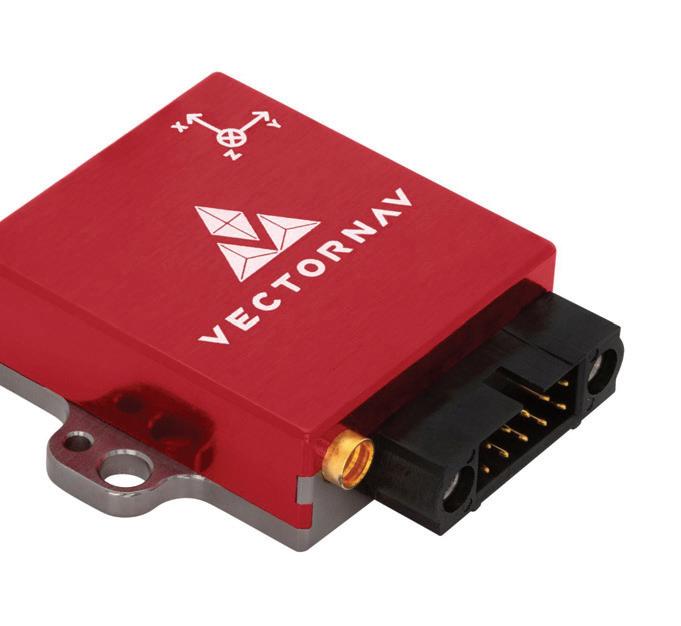
The VN 200 from VectorNav is a compact GNSS aided inertial navigation system (INS) designed for demanding industrial and automation environments.
It is designed to provide accurate real time position, velocity and orientation data by integrating inertial sensors with GNSS using advanced sensor fusion algorithms. This approach aims to ensure stable, reliable outputs even in dynamic conditions involving vibration, rapid motion or brief GNSS interruptions.
The VN 200 integrates tri axis gyroscopes, accelerometers, magnetometers and a high sensitivity GNSS receiver into a single unit, reducing system complexity and eliminating the need for custom fusion development. High data rates support fast moving platforms and control systems, making the VN 200 suitable for applications such as autonomous industrial vehicles, robotics, rail monitoring, mobile mapping and heavy machinery automation.
Available in both an ultra compact surface mount module and a ruggedised enclosure, the VN 200 offers flexibility for OEM integration or direct deployment in harsh field environments. Multiple interface options allow straightforward connection to controllers, embedded computers and automation platforms.
Metromatics Pty Ltd
www.metromatics.com.au
The pco.dimax 3.6 DS ST CLHS is a high speed, double shutter camera engineered to capture extremely fast phenomena with high precision and clarity. It offers 3.6 MP resolution (1984 × 1808) combined with double shutter CMOS technology, enabling over 1000 double images per second at full resolution.
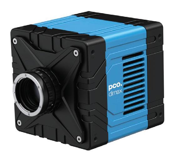
Its ultra short inter framing time of 250 ns makes it suitable for precise measurement of rapid motion in applications such as particle image velocimetry, flow visualisation, fluid dynamics, fuel injection and spray analysis, industrial production control and quality assurance, ballistics, combustion research, automotive airbag and impact testing, astronomy, wind tunnel studies and other high speed industrial processes.
The camera features a Camera Link HS FOL interface for real time streaming over eight 10 GB fibre connections, supporting continuous acquisition of uncompressed 10 bit data for high throughput workflows. Additional capabilities include 11 µm pixel size for high sensitivity, global and double shutter operation, flexible region of interest and binning options, and air or liquid cooled configurations for demanding environments.
SciTech Pty Ltd www.scitech.com.au
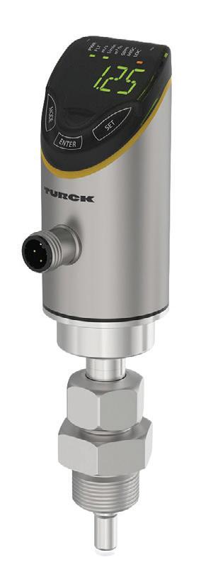
Turck has expanded its FS+ fluid sensor series with the introduction of the FS501 flow sensor.
The robust IP67 rated FS501 device is designed for pipe diameters from 15 to 250 mm and can be used across a broad range of applications. It can be used to measure both flow velocity and volume flow and is also designed to provide precise temperature values. Users can freely configure switching and analog outputs, while the sensor’s Smart Sensor Profile allows integration into IO Link environments. Smart Sensor Profile also provides direct access to process data and advanced functions such as ‘Single Value Teach’, which stores the current flow velocity as a switching point, as well as ‘Dynamic Teach’ and a ‘Totaliser’. The integrated intelligence of the FS501 is designed to reduce engineering effort while improving operational visibility.
The Totaliser function can also be used to determine machine consumption data directly within the sensor, supporting more transparent resource monitoring and enabling predictive maintenance strategies in automated production environments.
Turck Australia Pty Ltd www.turck.com.au/en
The WITT 85 30 SMART flashback arrestor offers an active monitoring function: the fitting not only stops flashbacks and backfires, but also detects them and immediately provides the information as a signal.
This changes the arrestor from a passive safety component into an active sensor within the gas system. Monitoring enables an immediate response to irregularities and lays the foundation for a stable, safe process. Personnel, plant and system components are protected even more effectively, and service life can be extended.
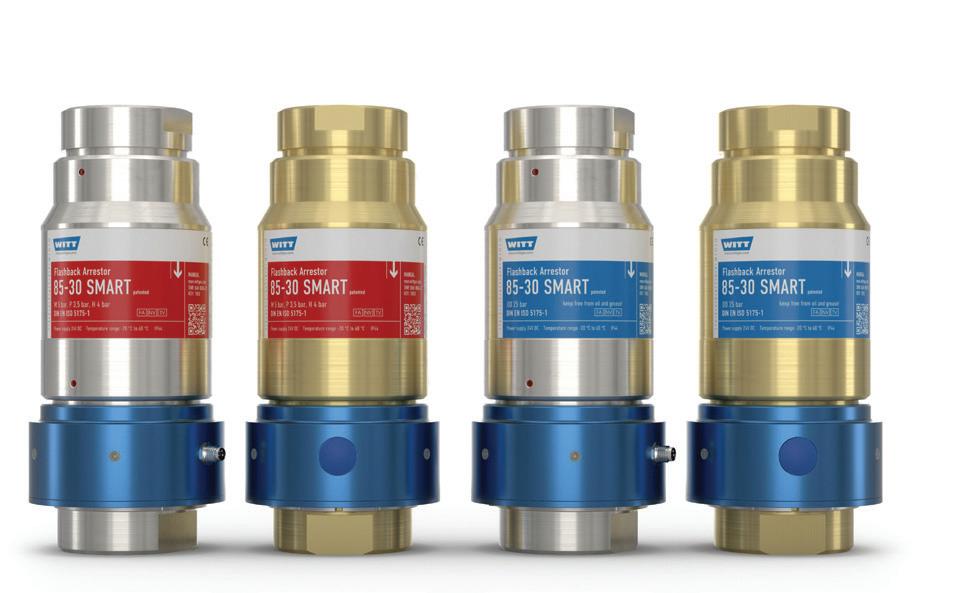
Technically, the SMART version is based on WITT’s existing 85 30 flashback arrestor. This features a flame arrestor made of sintered stainless steel, a temperature controlled backflow preventer, a gas non return valve and an integrated dirt filter. It is available in brass or stainless steel and is suitable for numerous gases such as acetylene, hydrogen, natural gas, liquefied petroleum gas and oxygen.
The 85 30 complies with the requirements for safety devices in accordance with DIN EN ISO 5175 1. The high reliability of the fitting is confirmed by external certification from the IBExU Institute.
Due to its signal transmission capabilities, the 85 30 SMART is more suitable for modern, digitally networked production environments, supporting the digitalisation of gas supply systems.
Niche Gas Products www.nichegas.com.au
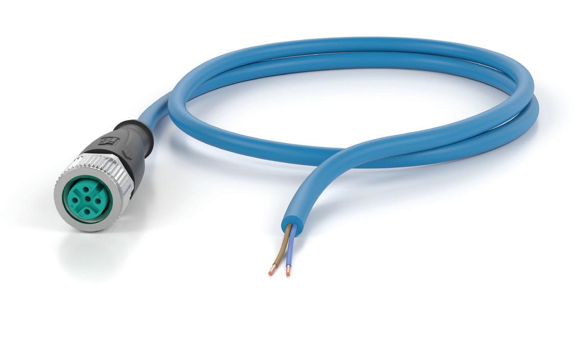
Pepperl+Fuchs has introduced ATEX certified M12 connectors designed for hazardous areas. Engineered to meet EN 61076 standards for intrinsically safe applications, these connectors combine high levels of safety, mechanical durability and simplified installation.
M12 connectors are the trusted standard for industrial automation, offering compact design, high protection ratings and easier installation. Designed for challenging industrial settings such as chemical, oil and gas plants, these connectors feature built in vibration protection that prevents hex nuts from loosening under shock or vibration. The result is long lasting, secure connections, increased system availability, longer maintenance intervals, and enhanced operational safety. Certified M12 cables and cordsets reduce the extensive verification efforts required for intrinsically safe circuits under IEC/EN 60079, NEC, and CEC standards. With EU type examination certificates, installers can save time, minimise errors and accelerate commissioning.
Pepperl+Fuchs (Aust) Pty Ltd www.pepperl-fuchs.com

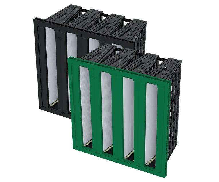
The Camfil CamGT 4V 300 turbine static air intake filter is engineered for facilities requiring high availability, and is designed for harsh environments, including coastal areas with high humidity and heavy rain.
The CamGT 4V 300 features premium hydrophobic EPA grades that actively limit media degradation, fouling and corrosion. Its aerodynamic support grid and high burst strength are designed to provide a consistently low and stable pressure drop, even under extreme weather conditions. Its lightweight construction also enables easy mounting, streamlining maintenance workflows and reducing equipment downtime.
The filter’s long life is said to directly improve overall turbine efficiency, while the use of EPA grades leads to better fuel efficiency and reduced CO₂ emissions per megawatt hour.
Camfil Australia Pty Ltd www.camfil.com.au
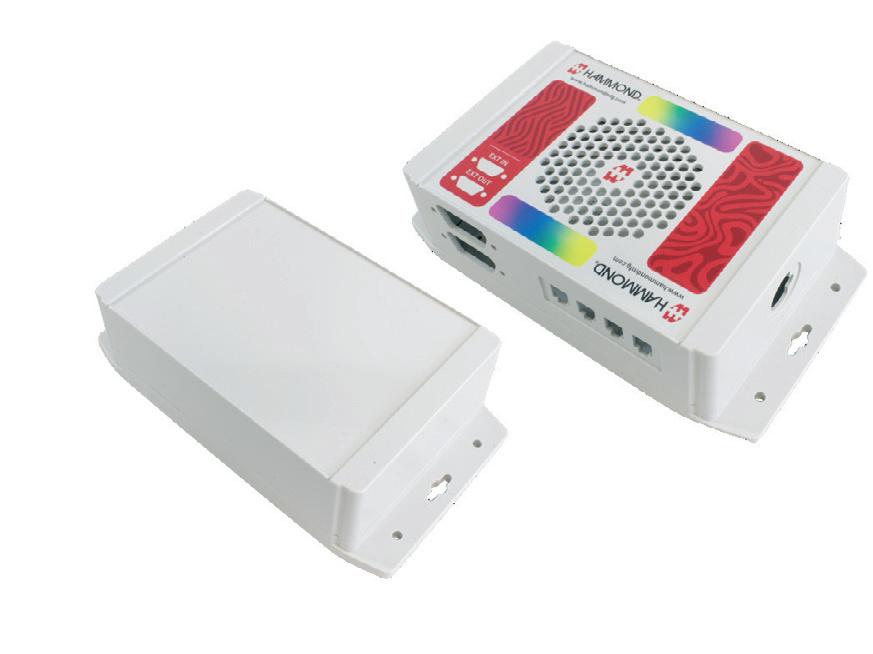
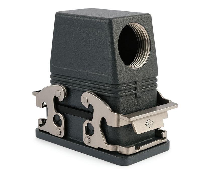
ILME offers a range of corrosion resistance connector enclosures, based on the principle that corrosion must never penetrate, affect the connector’s locking mechanisms, or contaminate internal contacts and terminations, as this would compromise electrical performance. Salt spray testing provides a controlled, repeatable benchmark to verify resistance levels beyond purely aesthetic standards.
Suitable for aggressive environments, the IP68 range is for railway applications and in environments where high pressure resistance, impact strength, and corrosion resistance are required. They are manufactured from aluminium die cast alloy with an epoxy polyester thermosetting powder coating, colour black RAL 9005, resistant to external agents and impacts. Gaskets are manufactured in anti ageing, oil resistant, grease resistant and fuel resistant NBR elastomer.
Meanwhile, ILME’s W TYPE enclosure series is designed for industrial applications with particularly aggressive external agents. Its advanced surface treatment delivers up to 50% higher corrosion resistance in salt spray testing compared to standard solutions. Manufactured from aluminium die cast alloy with a pre coating chromate conversion treatment, they also have FKM fluoroelastomer gaskets for improved resistance to chemicals and aging.
The E Xtreme series is built for the most demanding conditions with special protective coating applied prior to the finishing layer to provide maximum protection against pollution, erosion and long term exposure to corrosive agents, achieving up to 3000 hours of resistance in salt spray testing (EN ISO 9227).
Treotham Automation Pty Ltd www.treotham.com.au

Implementing zero trust in OT environments requires a holistic approach that unites informed people, rigorous processes and the right technology.
Not long ago, the operational technology (OT) networks used in environments such as factories and critical infrastructure were air gapped, meaning they were not connected to the internet. But today, the once siloed worlds of OT and information technology (IT) are seeing greater interconnectivity due to digital transformation and support for scarce or remote workers. This connectivity can enhance production via data sharing and new cloud based tools that allow organisations to tap into new business value. One of the main drawbacks of IT/OT convergence, however, is that ever evolving cyberthreats now have easier access to previously air gapped OT environments, jeopardising the benefits of this integration.
Operational technology systems are particularly vulnerable because they were designed to implicitly trust everything within their environments. Organisations should therefore be evolving towards a zero trust cybersecurity model, one that continuously verifies the trustworthiness of users and devices while controlling access based on contextual information.
Historically, industrial automation and control systems (IACS) designers, builders, manufacturers and operators knew what should and should not be trusted with
regard to protecting their systems. They could assume that their systems would not execute something that was dangerous to the human operator or the production line. Most IACS technologies were designed around the hypothetical concept of implied trust. This meant that any connections made within the air gapped OT perimeter were safe from any and all cyberthreats that proliferated in the outside world. This state of implied trust was mostly a successful security strategy for years because of OT’s isolation from the public internet.
Furthermore, industrial control system (ICS) assets are typically built for longevity. Deployed technologies may remain in working order for 20 years or more. There are often strong business justifications (as well as safety and reliability requirements) for continuing to operate older ICS equipment.1 Also, a future where outside connections to OT systems would become a common necessity was never really a consideration.
Now, operational technology environments are increasingly being connected with IT networks (also known as IT/OT convergence or Industry 4.0), which can deliver new strategic benefits. These include utilising cloud native capabilities and improving frontline decision making by using data from both IT and OT systems.2 This convergence can additionally reduce space requirements, eliminate physical

hardware, shorten deployment times, improve cost savings, boost performance, and reduce siloed IT and OT department resources. But these connections also puncture the OT air gap, thereby deflating the false notions of implied trust and ICS security by design.
IT environments are increasingly responsible for configuring and managing OT devices, as well as collecting and reporting on the critical data organisations need to effectively oversee their OT assets. This bridging of enterprise and industrial networks serves a clear business purpose, but as more IT assets shift to cloud based environments, OT assets are becoming

vulnerable to cybersecurity threats that were previously non existent.
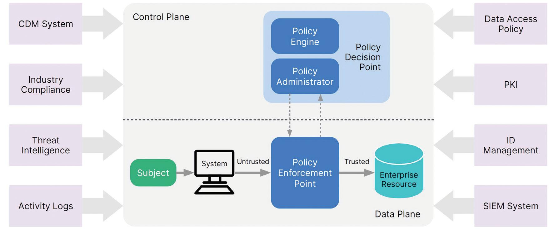
At a conceptual level, the term ‘zero trust’ shifts the thinking around security from an ‘implied trusted’ attitude to an ‘assumed breached’ state, where nothing is trusted without verifying.
In more practical terms, zero trust refers to a security model in which users and devices are no longer automatically granted access based on network location. Instead, it focuses on evaluating trust on a per transaction basis. Degrees of access can be
granted to verified users and devices based on the contextual factors surrounding the request. Reverification or re evaluation of permissions is frequent.
Approaches to implementing a zero trust model can vary greatly, and even some of the common solution initialisms can be confusing without detailed definitions.
• A zero-trust access (ZTA) solution focuses on identifying and having oversight of which users and devices are accessing the network. As more users work remotely and Industrial Internet of Things (IIoT) devices proliferate in OT environments, organisations should continuously verify
all users and devices as they access applications and data.
• A zero-trust network access (ZTNA) solution refers to application access in which no user or device is trusted to access an application unless they prove their credentials. Zero trust network access is often cited as a natural evolution from traditional virtual private network (VPN) tunnels, which assume anything that passes network perimeter controls can be trusted. Unlike a VPN, ZTNA extends the zero trust model beyond the network and reduces the attack surface by hiding applications from the internet.
An effective zero trust implementation can address several pressing cybersecurity needs facing organisations today, namely:
• Enabling full mobility of staff without disrupting normal operations or affecting the access control policies in place.
• Unifying the organisation’s security strategy with regard to users, assets and (indirectly) applications, regardless of where they are physically located.
• Helping prevent cyberthreats from spreading laterally throughout organisations by continuously reassessing user and device identity and posture on a per session basis.
The road from implied trust to zero trust isn’t without hurdles or complications. To effectively implement a zero trust solution such as ZTA within an OT environment, security leaders may need to address some questions that are particular to how ICS operates within the OT environment and any safety related aspects.
1. Does the warranty language of any current automation vendors restrict or limit what can happen on the network? This is a fairly frequent issue that should be fully investigated in advance.
2. Are the ZTA technologies compatible with the legacy technologies found in the OT environments? ICS longevity (20 year lifecycles) must be taken into account.
3. Asset owners often depend on system integrators and original equipment manufacturers (OEMs) for integration and commissioning. Are they prepared for the introduction of ZTA technologies that may disrupt currently integrated and commissioned subsystems?
4. Original equipment manufacturers and system integrators may also require remote access as part of their warranty or third party operation and maintenance contracts.
5. Typically, much of the ICS/OT technology stack is headless, making user interaction impossible. Internet Protocol (IP) addresses are often static, and it would be hard to imagine re authenticating a connection with a headless device lacking a user interface. Can the ZTA solution support this unique limitation of OT environments?
6. Because OT environments have historically been air gapped, they sometimes rely on static passwords rather than those managed in Active Directory (AD) with secure credential management policies.
7. Some OT components (for example PLCs and HMIs) may not support the technologies or protocols required to fully integrate with a ZTA implementation. As a result, a ZTA approach might not be practical for some OT devices or systems.
8. Some ICS technologies within the OT environment may be designated for safety operations and may require timely and uninterrupted access to systems to execute safety functions.

...ZERO

Thus, implementing ZTA for such an ICS shouldn’t impede the safety aspects of the infrastructure.
Another key challenge to implementing zero trust across interconnected IT/OT environments is that organisations need to establish distinct identities between the two sides of the business. Effectively embracing ZTA requires a solution capable of converged security operations for two management areas coming together with different priorities. Maintaining separate security operations centres (SOCs) for IT and OT increases complexity and potential risks when it comes to managing assets and policies in both environments, ingesting and analysing data from both IT and OT systems, and performing remediation actions in case of a cyber intrusion.
Acquiring and maintaining zero trust solutions will also call for internal know how and operational resources for managing logging and access controls. Combined with limited budgets, many organisations currently may struggle to find, hire and
retain the skilled security staff required to deploy and maintain zero trust solutions. In these instances, it may be important to consider whether a vendor offers the option of dedicated support services.
As IT/OT convergence continues to accelerate, security leaders should be evolving into a zero trust model to keep their OT environments safe from disruptions due to internal or external security events. Today’s path to deploying zero trust in OT is threefold:
1. People: Start raising awareness about the risks of IT/OT convergence with users and training them on how zero trust solutions can help secure the organisation against opportunistic threats.
2. Process: The era of security based on implied trust in OT is over. Any security policies and protocols should now be based on trust that is contextually verified and constantly reverified. Organisations need complete and
continuous control over who and what is on the network, including automation vendors and service providers.
3. Technology: Evaluate zero trust solutions for OT environments and be mindful that they may also impact your broader supply chain. Look for a zero trust security vendor with strong partnerships across the technology ecosystem. Ultimately, successfully implementing zero trust in OT environments requires a holistic approach — one that unites informed people, rigorous processes and the right technology to build a resilient and secure operational foundation.
1. Benestelli B and Kambic D 2022, IT, OT, and ZT: Implementing Zero Trust in Industrial Control Systems, Carnegie Mellon University,<<https://www.sei.cmu. edu/blog/it ot and zt implementing zero trust in industrial control systems/>>
2. Chang M, Koerber B and Soganci M 2022, Converge IT and OT to turbocharge business operations’ scaling power, McKinsey & Company,<<https://www. mckinsey.com/capabilities/operations/our insights/ converge it and ot to turbocharge business operations scaling power>>
3. NIST 2020, SP 800-207: Zero Trust Architecture,<<https:// csrc.nist.gov/pubs/sp/800/207/final>>
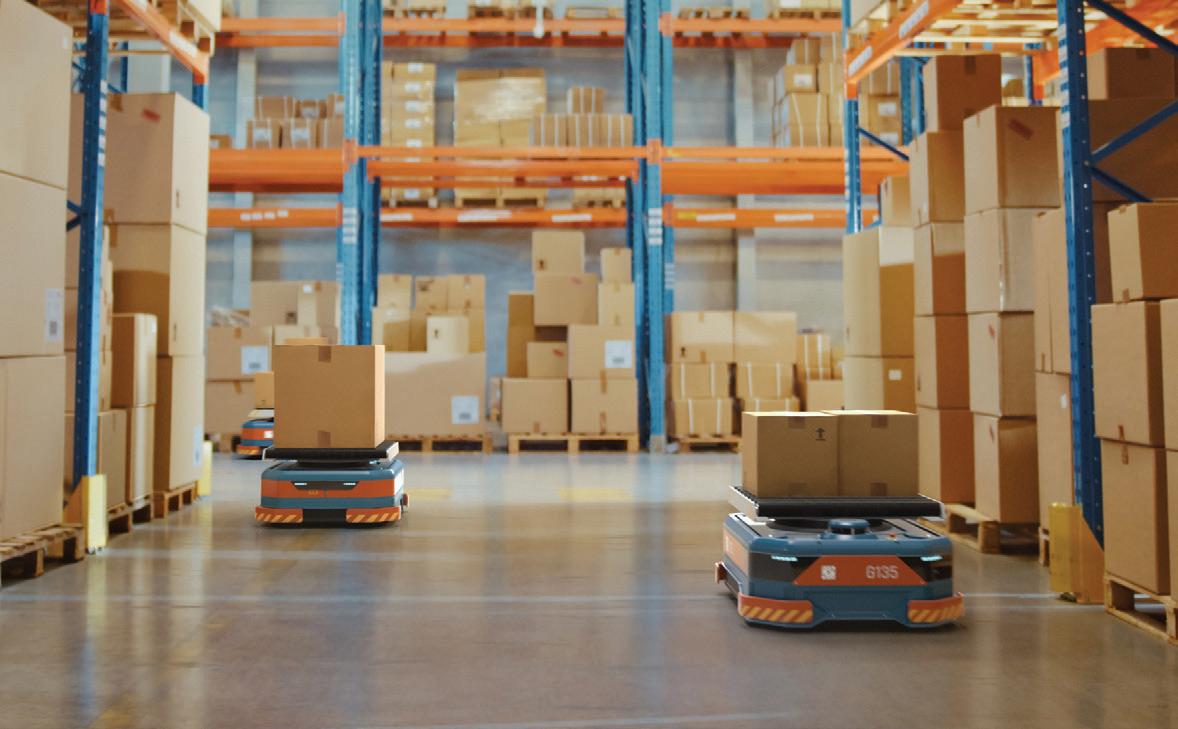
Inside large autonomous warehouses, hundreds of robots move around as they collect and distribute items. In this busy environment, even small traffic jams or minor collisions can snowball into massive slowdowns.
To avoid such an avalanche of inefficiencies, researchers from MIT and the tech firm Symbotic developed a new method that automatically keeps a fleet of robots moving smoothly. Their method learns which robots should go first at each moment, based on how congestion is forming, and adapts to prioritise robots that are about to get stuck. In this way, the system can reroute robots in advance to avoid bottlenecks.
The hybrid system utilises deep reinforcement learning, a powerful artificial intelligence method for solving complex problems, to figure out which robots should be prioritised. Then a fast and reliable planning algorithm feeds instructions to the robots, enabling them to respond rapidly in constantly changing conditions.
In simulations inspired by actual e commerce warehouse layouts, this new approach achieved about a 25% gain in throughput over other methods. Importantly, the system can quickly adapt to new environments with different quantities of robots or varied warehouse layouts.
“There are a lot of decision making problems in manufacturing and logistics where companies rely on algorithms designed by human experts. But we have shown that, with the power of deep reinforcement learning, we can achieve super human performance. This is a very promising approach, because in these giant warehouses even a 2 or 3% increase in throughput can have a huge impact,” said Han Zheng, a graduate student in the Laboratory for Information and Decision Systems (LIDS) at MIT, and lead author of a paper on this new approach.
Coordinating hundreds of robots in an e commerce warehouse simultaneously is no easy task. The problem is especially complicated because the warehouse is a dynamic environment, and robots continually receive new tasks after reaching their goals. They need to be rapidly redirected as they leave and enter the warehouse floor.
Companies often leverage algorithms written by human experts to determine where and when robots should move to maximise the number of packages they can handle.
But if there is congestion or a collision, a firm may have no choice but to shut down the entire warehouse for hours to manually sort the problem out.
“In this setting, we don’t have an exact prediction of the future. We only know what the future might hold, in terms of the packages that come in or the distribution of future orders,” Zheng said. “The planning system needs to be adaptive to these changes as the warehouse operations go on.”
The MIT researchers achieved this adaptability using machine learning. They began by designing a neural network model to take observations of the warehouse environment and decide how to prioritise the robots. They train this model using deep reinforcement learning, a trial and error method in which the model learns to control robots in simulations that mimic actual warehouses. The model is rewarded for making decisions that increase overall throughput while avoiding conflicts.
Over time, the neural network learns to coordinate many robots efficiently.
“By interacting with simulations inspired by real warehouse layouts, our system receives feedback that we use to make its decision making more intelligent. The trained neural network can then adapt to warehouses with different layouts,” Zheng explained.
It is designed to capture the long term constraints and obstacles in each robot’s path,
while also considering dynamic interactions between robots as they move through the warehouse. By predicting current and future robot interactions, the model plans to avoid congestion before it happens.
After the neural network decides which robots should receive priority, the system employs a tried and true planning algorithm to tell each robot how to move from one point to another. This efficient algorithm helps the robots react quickly in the changing warehouse environment.
Once the researchers trained the neural network, they tested the system in simulated warehouses that were different from those it had seen during training. Since industrial simulations were too inefficient for this complex problem, the researchers designed their own environments to mimic what happens in actual warehouses.
On average, their hybrid learning based approach achieved 25% greater throughput than traditional algorithms as well as a random search method, in terms of number of packages delivered per robot. Their approach could also generate feasible robot path plans that overcame congestion caused by traditional methods.
“Especially when the density of robots in the warehouse goes up, the complexity scales exponentially, and these traditional methods quickly start to break down. In these environments, our method is much more efficient,” Zheng said.

BRIDGING THE GAP BETWEEN SAFETY COMPLIANCE AND EFFICIENT DEPLOYMENT.
Talk to process engineers and a common frustration quickly emerges around implementing Safety Instrumented Systems (SIS): many plants need certified safety coverage or a logic solver for just a handful of loops, such as an overpressure interlock, pump shutdown or high-temperature trip. Yet the available options are often mismatched to the need. On one end is a basic alarm device for a single function or loop that falls just short of requirements; on the other, you have a full safety PLC that meets the requirements but comes at a cost far beyond what the application justifies. This in-between space, commonly referred to as the ‘safety gap’, is where much of the real-world SIS work resides, and it has remained underserved for years.
The challenge with defaulting to a safety PLC
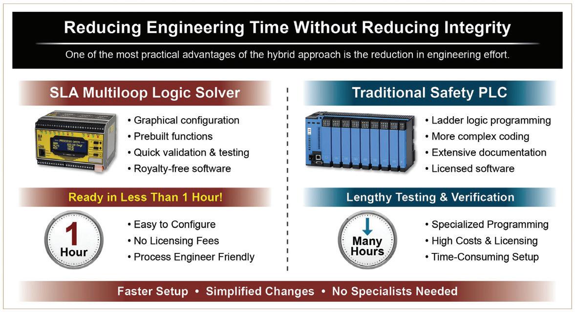
Specifying a safety PLC for a small SIF (Safety Instrumented Function) is technically defensible under IEC 61511. No one’s going to argue that it is incapable, but in practice, it often creates headaches that outlast the original project. Oftentimes, you are buying more equipment than you need. With these larger, more complex safety logic solvers, you are locked into licensed programming software and complex architectures, where even minor logic changes often require waiting on a certified specialist. This leaves many plants with safety systems that are costly to commission, difficult to modify, and more complex than the application truly demands.
A better fit: multi loop logic solvers
When point and loop counts are smaller, or when safety loops are not centralised, users should consider installing a logic solver that handles more than one loop but has some of the advanced functionality of the larger safety PLCs. The Moore Industries SLA Multifunctional Safety Logic Solver
and Alarm sits squarely in the safety gap. It is exida certified to IEC 61508:2010 with systematic integrity to SIL 3, random integrity to SIL 2, but packaged more like a field instrument than a control system. With up to six analog inputs, 16 internal alarms, and eight physical alarm outputs, simple and complex alarming strategies can be implemented with easy-to-use dropdown menus, radio buttons and check boxes. Even complex alarm voting architectures like 1oo2, 2oo3 and 3oo5 are simple to employ.
Integration with existing control and monitoring systems is straightforward as the SLA supports Modbus/TCP and Modbus RTU industrial protocols. An embedded read-only web server also allows all inputs, outputs, internal variables and various other parameters to be read with a simple web browser.
Configuration without complexity
Setting up an SLA-based safety function is secure, straightforward and hassle-free. No custom or licensed software is required with the SLA, as it is programmed with any FDTcompliant host, such as PACTware. Along with configuration and setup, the SLA’s DTM also includes full monitoring and simulation capabilities that allow users to test alarming and safety functions before installation or commissioning. For more advanced safety functions, the SLA’s powerful but easy-touse equation/expression editor enables the
creation of monitoring, alarming and control schemes that involve simple to complex equations using timers, running min/max functions, prebuilt analog and discrete logic functions, and more.
This means process engineers can more easily own the safety function from commissioning through future modifications, removing a common bottleneck on sites where certified safety PLC specialists are sometimes in short supply.
Getting the size right
The push for functional safety compliance has produced better outcomes across process industries, but it has also driven some unnecessary spending. For small SIS applications, a right-sized solution can often deliver the same certified protection at a fraction of the cost and engineering overhead.
The Moore Industries SLA isn’t intended to replace a safety PLC where one is truly required. But for the many applications that fall into the safety gap, it delivers what the market has long lacked: a certified, practical, field-ready solution that keeps you compliant without forcing unnecessary complexity or cost.
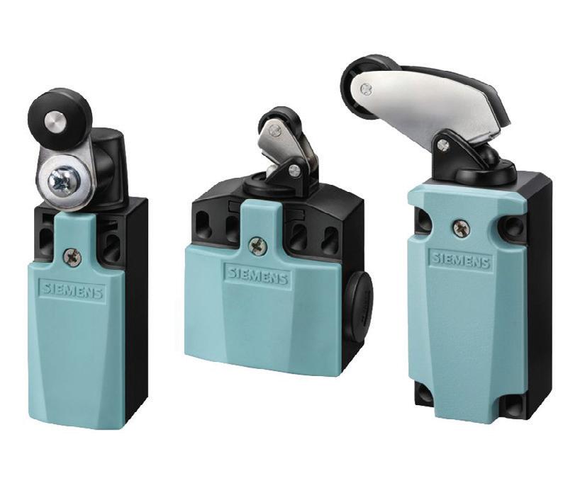
Siemens SIRIUS limit switches are designed to deliver precise position detection and dependable switching performance across a wide range of applications. Designed as part of the SIRIUS modular system, the switches offer flexibility, durability and easy integration into modern control architectures.
The 3SE5 series features a robust metal or plastic enclosure for high resistance to mechanical stress, dust and moisture, making them suitable for harsh conditions commonly found in manufacturing, materials handling and process industries. With a wide selection of actuator heads — including plunger, roller lever and rotary types — SIRIUS limit switches can be tailored to suit specific motion detection requirements.
Engineered for long service life, the switches incorporate high quality contacts that provide consistent switching accuracy over millions of operating cycles. Their modular design allows for easy configuration and maintenance, reducing downtime and simplifying installation. In addition, positive opening operation supports enhanced safety in critical applications.
SIRIUS limit switches also support a broad range of electrical ratings and connection options, enabling compatibility with various control systems. Whether used for position monitoring, end of travel detection or safety interlocking, they are designed to provide a reliable and efficient solution.
APS Industrial www.apsindustrial.com.au
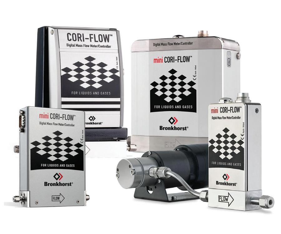
The mini CORI FLOW series by Bronkhorst are compact mass flowmeters and controllers based on the Coriolis measuring principle. Designed to cover the needs of the low flow market, there are three models to overlap flow ranges from 5 g/h up to 30 kg/h (full scale values), each offering multi range functionality. Factory calibrated ranges can be rescaled by the user, maintaining the original accuracy specifications. As a result, users are able to reduce the variety of instruments and thus reduce the cost of ownership.
The instruments are equipped with a robust IP65 weatherproof housing and are available with optional ATEX approval for use in Zone 2 hazardous areas.
Instruments of the mini CORI FLOW series contain a uniquely shaped, single loop sensor tube, forming part of an oscillating system. When a fluid flows through the tube, Coriolis forces cause a variable phase shift, which is detected by sensors and fed into the integrally mounted PC board. The resulting output signal is strictly proportional to the real mass flow rate. Coriolis mass flow measurement is fast, accurate and inherently bi directional. The mini CORI FLOW meters also feature density and temperature of the fluid as secondary outputs. Coriolis flowmeters are offer high accuracy and when applied for liquids, the mass flow accuracy is better than ±0.2% Rd.
The mini CORI FLOW meters can be applied to the mass flow measurement of most liquid types. They are fully metal sealed, and the controllers have a high performance elastomeric valve seat made of Kalrez.
AMS Instrumentation & Calibration Pty Ltd www.ams-ic.com.au
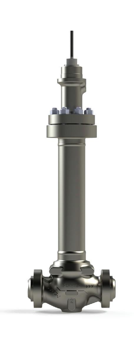
Emerson has introduced the Fisher IC2 cryogenic top entry control valve, designed for cold box applications in air separation units, hydrogen liquefaction and LNG production. Cold boxes are insulated enclosures that house cryogenic equipment, such as heat exchangers, distillation columns, piping and valves. The IC2 control valve meets the demands of these extremely low temperature environments, operating reliably at temperatures as low as 269°C.
Operating in cryogenic environments can be challenging due to various factors, including product and energy losses due to emissions, which lead to reduced profitability, high maintenance costs and regulatory concerns. To address these and other issues, the IC2 control valve includes cryogenic enhancements, including a narrow extension diameter and fluid baffle.
These components work together to minimise heat conduction, thereby reducing the energy required to maintain process fluid temperatures, while enhancing overall operational sustainability. The IC2 control valve’s Fisher enhanced ENVIRO SEAL packing system and bellows limit leakage to a maximum of 100 parts per million by volume, meeting or surpassing US Environmental Protection Agency standards.
The Fisher IC2 control valve provides longevity with its hardened trim materials, enhanced ENVIRO SEAL packing and metal to metal seating. When maintenance is necessary, the IC2 valve offers simple serviceability via features such as top entry, a single packing nut, a modular stem assembly, an independently replaceable bellows and a replaceable valve plug and seat ring.
The IC2 control valve is rated for the CL600 pressure class, and is available in line sizes from DN25 to DN100.
Emerson www.emerson.com/au/automation
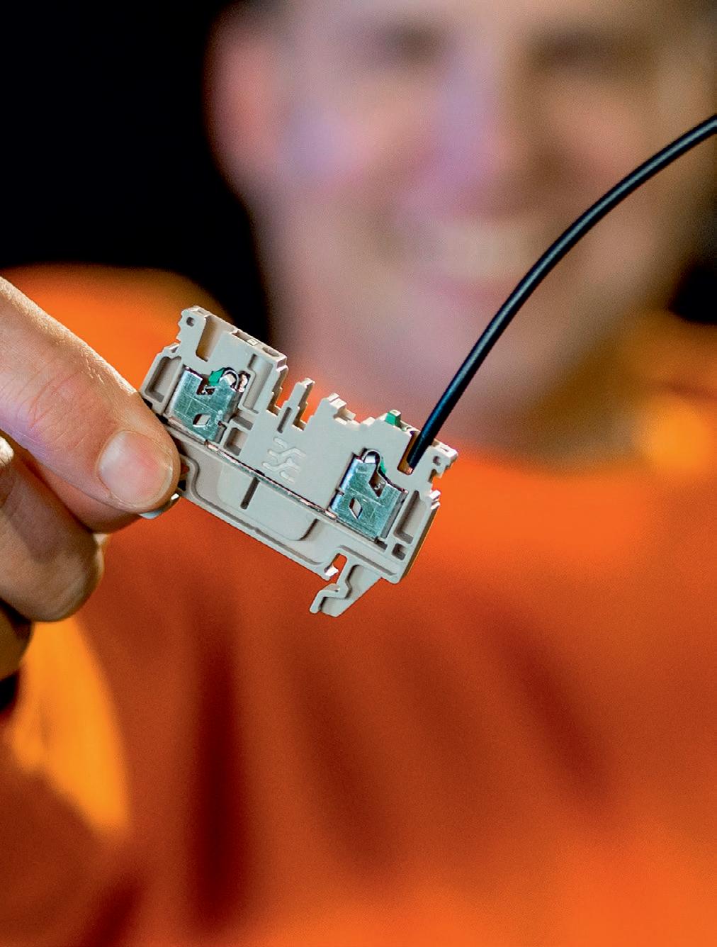
While variable speed drives can greatly improve energy efficiency, they can introduce other problems that shorten the life of motor bearings.
Bevan Christiansen, Global Segment Manager, NEMA Motors, ABB
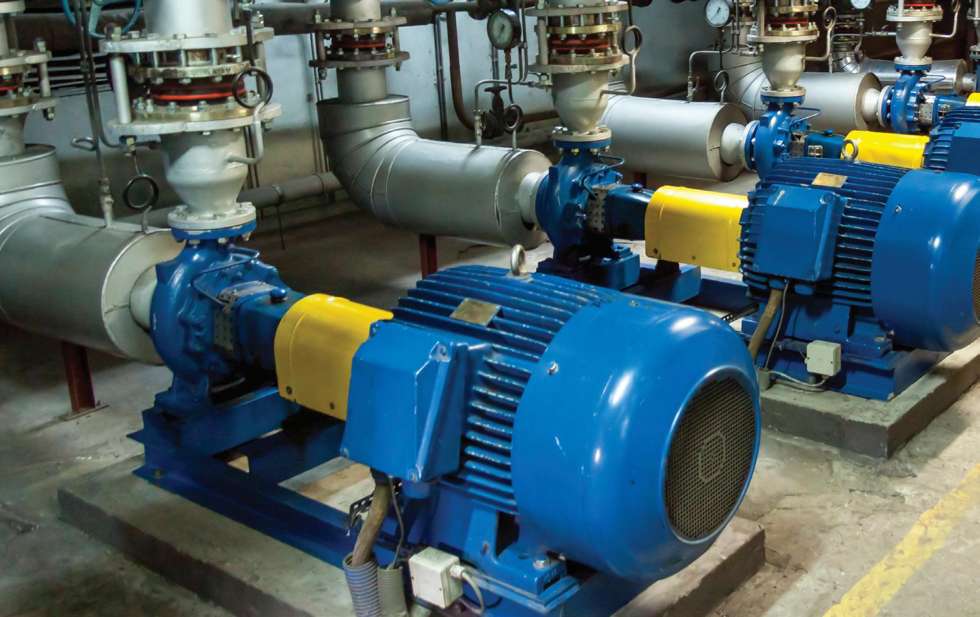
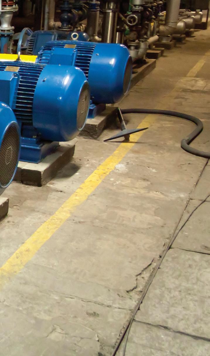
Electric motors play a vital role in our everyday lives — where we live, work and play. Simply put, they make almost everything that moves, move. Nearly 70% of electricity consumed by industry is used by electric motor systems1
Roughly 75% of the industrial motors in operation are used to run pumps, fans and compressors, a category of machinery that is highly susceptible to major efficiency improvements2. These applications often operate at constant speed, all the time, even
when not needed. This constant operation wastes energy and produces unnecessary CO2 emissions, but by controlling a motor’s speed, we can reduce power consumption, saving energy and reducing environmental impact.
One way to control a motor’s speed is through the use of a variable speed drive (VSD), a device that regulates an electric motor’s rotational speed by varying the frequency and voltage supplied to the motor. By controlling a motor’s speed, a drive can reduce power consumption (for example,
reducing rotating equipment speed by 20% can reduce input power requirements by approximately 50%3) and provide a considerable improvement in process control and a significant cost of operation savings over the life of the motor.
As useful as VSDs are for saving energy in many applications, they can cause premature motor failure if not properly grounded. While there are many different causes of electric motor failures, the most common issue when using a drive is bearing failure caused by common mode voltage.
DAMAGE CAUSED BY COMMON MODE VOLTAGE
In a 3 phase AC system, common mode voltage can be defined as the imbalance present between the three phases created by the pulse width modulated power of the drive, or the voltage difference between the power source ground and the neutral point of the 3 phase load. This fluctuating common mode voltage electrostatically induces voltage on the motor’s shaft, and this shaft voltage can discharge through the windings or through the bearings. Modern engineering designs, phase insulation and
inverter spike resistant wire can help protect the windings; however, when the rotor sees a build up of voltage, the current seeks a path of least resistance to ground. In the case of an electric motor, this path runs directly through the bearings.
Since motor bearings utilise grease for lubrication, the oil in the grease forms a film that acts as a dielectric, which means it can transmit the electric forces without conduction. Over time though, this dielectric breaks down. Without the insulating properties of the grease, the shaft voltage will discharge through the bearings, then through the motor’s housing, to achieve electrical earth ground. This movement of electrical current causes arcing in the bearings, commonly referred to as electrical discharge machining (EDM). As this continual arcing occurs over time, the surface areas in the bearing race become brittle, and tiny pieces of metal can break off inside the bearing. Eventually, the damaged material works its way between the bearing’s balls and races, causing a grinding effect, which can produce micron sized pitting, called frosting, or washboard like ridges in the bearing raceway, called fluting.
Some motors can continue to run as the damage gets progressively worse, without any noticeable issues. The first sign of bearing damage is usually an audible noise, due to the bearing balls travelling over the pitted and frosted areas. But by the time this noise occurs, the damage has usually become substantial enough that failure is imminent.
WHILE THERE ARE MANY DIFFERENT CAUSES OF ELECTRIC MOTOR FAILURES, THE MOST COMMON ISSUE WHEN USING A DRIVE IS BEARING FAILURE CAUSED BY COMMON MODE VOLTAGE
Some industrial applications do not experience these bearing difficulties on variable speed motors, but in many installations robust grounding is not always available. In these instances, another method must be used to divert this current away from the bearings. The most common solution is to add a shaft grounding device to one end of the motor shaft, especially in applications where common mode voltage can be more prevalent. A shaft ground is essentially a means to connect the turning rotor of the motor to earth ground via the frame of the motor. Adding a shaft grounding device to the motor prior to installation (or buying a motor with one preinstalled) can be a small price to pay when compared to the price tag of maintenance costs associated with bearing replacement, not to mention the high costs of downtime in a facility.
There are several common types of shaft grounding devices in the industry today, such as carbon brushes, ring style fibre brushes and grounding bearing isolators; and other methods of protecting the bearings are also available.
Carbon brushes have been in use for more than 100 years and are similar to the carbon brushes used on DC motor commutators. Grounding brushes provide the electrical connection between the rotating and stationary portions of the motor’s electrical circuit and take the current from the rotor to ground so that the charge does not build up on the rotor to the point where it discharges through the bearings. Grounding brushes offer a practical and economical means to provide a low impedance path to ground, especially for larger frame motors; however, they are not without their drawbacks. As with DC motors, the brushes are subject to wear because of the mechanical contact with the shaft, and, regardless of the design of the brush holder, the assembly must be periodically inspected to assure proper contact between the brushes and the shaft.
Shaft grounding rings work like a carbon brush, but they contain multiple strands of electrically conductive fibres arranged inside a ring around the shaft. The outside of the ring, which is typically mounted to the endplate of the motor, remains stationary, while the brushes ride on the surface of the motor shaft, directing the current through the brushes and safely to ground. Unlike carbon brushes, shaft grounding rings can be mounted inside the motor, allowing them to be used on washdown duty and dirty duty motors. No shaft grounding method is perfect, however, and grounding rings mounted externally tend to collect contaminants on their bristles, which may reduce their effectiveness.
Grounding bearing isolators combine two technologies: a 2 part, noncontact isolation shield that uses a labyrinth design to prevent ingress of contaminants; and a metallic rotor and isolated conductive filament ring to divert shaft currents away from the bearings. Since these devices also prevent lubricant loss and contamination, they replace standard bearing seals and traditional bearing isolators.
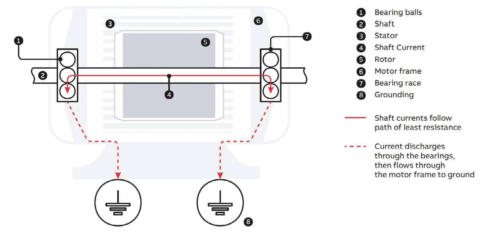
Another way to prevent a discharge of current through the bearings is to manufacture the bearings from a nonconducting material. In ceramic bearings, ceramic coated balls protect the bearings by preventing shaft current from flowing through the bearings to the motor. Since no electrical current flows through the motor bearings, there is little chance of current induced wear; however, the current will seek a path to ground, which means it will go through attached equipment.
Since ceramic bearings will not remove the current from the rotor, only specific direct drive applications are recommended for motors with ceramic bearings. Other drawbacks are the cost for this style of motor bearing and the fact that the bearings are usually available only up to size 6311.
On motors larger than 75 kW, it is generally recommended that an insulated bearing be installed on the opposite end of the motor on which the shaft grounding device is installed, regardless of which style of shaft grounding is used.
Three considerations for the maintenance engineer when trying to reduce common mode voltage in variable speed applications are:
Method Pros
Carbon brushes
• Effective, tried-and-true system
• Practical, economical
Shaft grounding rings
Grounding bearing isolators
Ceramic bearings
• Can be mounted internally
• Low maintenance - no adjustment necessary
• Also prevent lubrication loss and contamination
• Low maintenance necessary
• Won’t micro-weld
• Deflection resistant
• Corrosion resistant
• Low thermal expansion
1. Ensure that the motor (and motor system) is properly grounded.
2. Determine the proper carrier frequency balance, which will minimise noise levels as well as voltage imbalance.
3. If a shaft grounding device is deemed necessary, select one that works best for the application.
When a bearing current is present, there is no one size fits all solution. It is vital for the end user and motor and drive supplier to work together to identify the
Cons
• Subject to failure and corrosion
• High maintenance - need to be adjusted periodically
• Can’t be used in washdown duty or explosion-proof motors
• Collect contaminants
• Not suitable for high moisture environments
• Does not effectively retain oil mist
• Shaft currents are still present
• Susceptible to thermal shock from temperature fluctuation
• High cost
• Lower load capacity than metal bearings
most appropriate solution for the specific application.
1. Fong J, Fernando J et al 2020, “IEC61800 9 System Standards as a Tool to Boost the Efficiency of Electric Motor Driven Systems Worldwide,” Inventions, vol 5, issue 2, <<https://www.mdpi. com/2411 5134/5/2/20/>>
2. Reine P, Campos I and Schiller K 2020, Motor-Driven Equipment Research Package 2020, Omdia,<<https:// omdia.tech.informa.com/ /media/tech/omdia/ brochures/electric motor systems/fans blowers database 2020.aspx>>
3. US Department of Energy 2012, Energy Tips: Motor Systems, DOE/GO-102012-3730, <<https:// www. energy.gov/sites/prod/files/2014/04/f15/motor_tip_ sheet11.pdf>

Australia’s industrial sector is under increasing pressure to reduce emissions while maintaining productivity and reliability. Rising energy costs, tighter decarbonisation policies and growing demand for sustainable operations are driving companies to rethink how equipment and power systems are designed and operated. Across the mining, oil and gas, manufacturing and infrastructure sectors, electrification and energy-efficient system design are emerging as practical pathways towards decarbonisation.
For many industrial sites, particularly in remote and off-grid environments, diesel-powered systems have traditionally been the only viable option. However, advances in electrified drive technology, battery storage and smarter hydraulic system engineering are now creating opportunities to complement existing diesel infrastructure, helping industrial operators reduce fuel consumption, maintenance requirements and carbon emissions while maintaining reliability.
One area gaining attention is the electrification of hydraulic power systems. Conventional diesel-driven hydraulic power units (HPUs) are widely used across heavy industries, but they often operate inefficiently, particularly in intermittent-duty applications where engines remain running while demand fluctuates. This leads to unnecessary fuel burn, increased servicing requirements and higher operating costs.
Through system engineering and redesign, these systems can be optimised using a combination of electric drive technologies, hybrid architectures and energy-effi cient solutions that improve overall efficiency while supporting decarbonisation objectives. HYDAC Australia has been working with customers to develop electrified hydraulic systems using advanced drive technologies such as ENGIRO motors and integrated system solutions designed for industrial applications.
A recent project delivered for an oil and gas customer in Queensland demonstrated the benefits of this approach. The customer operated diesel-driven hydraulic equipment in a remote mining area with limited infrastructure and no access to grid power. The hydraulic system was required intermittently to erect and operate machinery critical to site operations.
HYDAC engineered and integrated an electrified hydraulic solution using an ENGIRO efficiency drive with interior permanent magnet (IPM) technology to complement the existing site infrastructure. The system reduced reliance on diesel operation while maintaining the
reliability and flexibility required for remote industrial applications.
The result was a more reliable and efficient hydraulic system with reduced servicing requirements, lower fuel costs and reduced emissions. In remote applications where maintenance access can be difficult and expensive, reducing engine servicing intervals also delivered significant operational benefits.
Battery energy storage is also emerging as a practical solution for reducing reliance on standby diesel generators. Across many remote industrial and mining sites, generators are commonly left in standby mode to ensure sufficient backup power is available to start critical equipment and applications when required. While effective, this approach often results in unnecessary fuel consumption and ongoing engine maintenance, even during periods of low demand.
Battery-based backup systems can provide a complementary or hybrid solution alongside existing diesel infrastructure. By integrating battery storage with existing generator infrastructure, sites can reduce generator runtime, lower fuel consumption and minimise emissions while still maintaining the reliability and backup capability required for critical operations. In some applications, battery systems can also improve system responsiveness and energy efficiency by supplying instant power during startup or peak demand events.
As industries continue progressing towards lower-emission operations, the focus is shifting towards smarter system integration, where existing infrastructure can be enhanced through more energy-efficient technologies and hybrid solutions. Smarter system engineering, energy-efficient drive technologies and integrated electrified solutions are becoming essential tools for improving productivity while supporting long-term sustainability goals.
For Australian industry, decarbonisation is no longer only about meeting policy requirements, it is increasingly becoming an operational and commercial advantage. Companies that invest in higher-efficiency systems today are positioning themselves to reduce operating costs, improve reliability and prepare for the future energy landscape.

Modern industrial facilities require machines, sensors and control systems to communicate with one another fast and reliably. Traditional wired connections are often inflexible, and wireless solutions are susceptible to interference. Li Fi Grathus, developed by the Fraunhofer Institute for Photonic Microsystems IPMS, is designed to address this challenge. The technology uses light for data transmission (Li Fi), providing a wireless connection that does not rely on radio waves. With data rates of 1 Gb/s or more and a range of up to 10 m, the system is suitable for many industrial applications. A key advantage is its extremely short and predictable (deterministic) latency of less than 100 ns, about 10,000 times lower than 5G and Wi Fi. This allows for truly real time data transmission, which is crucial for robotics and precise machine control.
Using light signals instead of radio waves gives Li Fi Grathus a key advantage: immunity to electromagnetic interference (EMI), which is common in industrial environments. The system also supports full duplex communication, transmitting and receiving simultaneously, which ensures uninterrupted data flow and prevents any time loss. It can be seamlessly integrated into existing systems and networks without major modifications and supports common industrial standards, such as Profinet, EtherCAT, EtherCAT G, SERCOS III and Time Sensitive Networking (TSN). In addition to Ethernet and Gigabit Ethernet, it supports USB 3.0/3.1 and user specific interfaces. An additional side channel with 1 Mb/s supports management, diagnostics and safety signals.
In addition to performance, ease of use is crucial in practical industrial settings. Li Fi Grathus is designed to offer easy installation: unlike complex optical systems such as free space
setups, which require time consuming alignment, or costly solutions like beam steering or adaptive optics, Li Fi Grathus can be installed and operated flexibly without any adjustments. A patented multi path lens allows higher transmission power and simple manual alignment.
Its thermally stable, compact, plug and play design with metal housing protects the technology in everyday industrial use, and eye safety is ensured through the use of Class 1 laser technology.
With its reliable, real time communication between control, sensor and actuator systems, Li Fi Grathus is designed for applications that require fast, wireless data transmission. Typical use cases include industrial automation, robotics, motion control, large rotating machinery, logistics systems and high bandwidth channels for uploading and downloading sensor data in
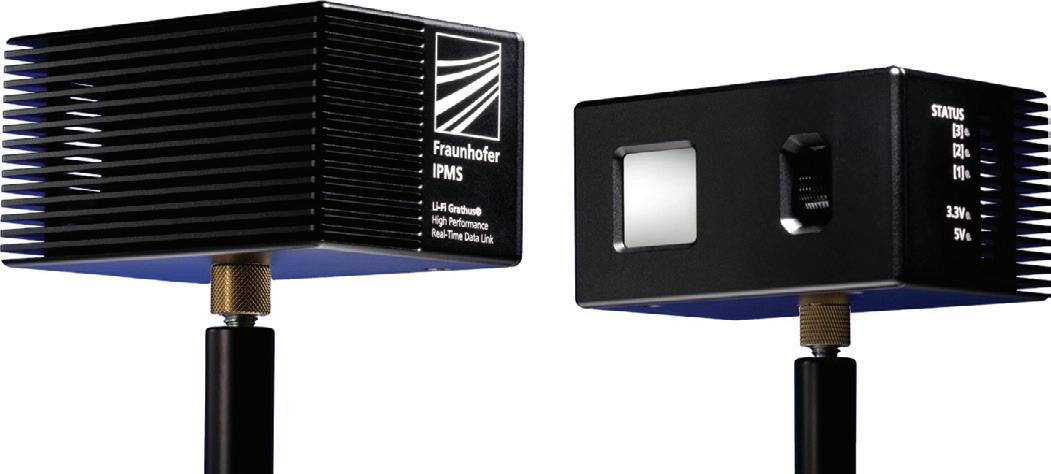
automated guided vehicles (AGVs), as well as backhaul and backbone connections for Wi Fi and cellular access points.
Wireless connectivity offers significant advantages, especially in flexible production environments, where machines are frequently reconfigured without compromising deterministic performance. It also ensures reliable operation in metallic environments, which are challenging for traditional radio technologies and can lead to failures.
“Li Fi Grathus builds on more than 15 years of Li Fi expertise at Fraunhofer IPMS,” said Dr René Kirrbach, Group Leader for Li Fi at Fraunhofer IPMS. “Our latest development provides fast, secure, real time optical wireless communication for industrial applications and is compatible with numerous industrial Ethernet standards. Its robust design makes it ideal for demanding industrial environments.”
Li Fi Grathus is available as an evaluation kit; a ‘ready to use’ set that enables the easy replacement of a wired 1 Gbps Ethernet connection with an optical link via plug and play, while also allowing testing of the technology’s basic functions in practice. The kit includes two Grathus modules, two Ethernet cables, a power supply and a user manual.
Fraunhofer Institute for Photonic Microsystems IPMS www.ipms.fraunhofer.de/en.html

Ella Averill-Russell, IICA Sydney Branch Manager
Across Australia, decarbonisation is rapidly reshaping industry. What was once viewed primarily as an environmental initiative is now becoming a major operational and technological transformation across mining, manufacturing, utilities, transport and other critical infrastructure.
However, decarbonisation is not simply about renewable energy generation. Increasingly, it is about data, automation, visibility and intelligent operational control.
To improve energy efficiency, monitor emissions, optimise processes, electrify operations and integrate renewable systems, industrial facilities now rely heavily on connected OT environments. Smart sensors, industrial networks, edge devices, real-time analytics, cloud platforms and AI-assisted monitoring are becoming essential to how industrial sites operate.
This shift is particularly significant for Australia, as many industrial facilities still operate using legacy automation infrastructure originally designed decades ago.
Existing PLCs, SCADA systems, fieldbus networks and plant-floor communication systems were built for reliability and uptime, not for today’s highly connected, data-driven industrial environments.
For many operators, complete infrastructure overhauls introduce excessive cost, operational disruption, downtime risk and workforce challenges. Instead, the industry is increasingly moving towards staged modernisation strategies that allow legacy systems to remain operational while progressively integrating modern OT software, industrial cybersecurity frameworks, data acquisition systems, cloud connectivity and interoperable communication architectures. This allows facilities to modernise at a manageable pace while continuing to operate.
Importantly, this transformation is no longer being driven purely by hardware. The real shift is occurring through the combination of software intelligence, industrial networking, operational data visibility and cybersecurity resilience.
Modern OT software platforms can now deliver real-time operational visibility, predictive maintenance analytics, energy optimisation, asset lifecycle management, remote support capabilities and integrated reporting across previously isolated systems. This enables organisations to extract greater value from existing infrastructure while preparing operations for future industrial demands.
However, increased connectivity also introduces major cybersecurity concerns for industrial facilities. Historically, industrial environments operated largely in isolation. Today, many sites rely on remote access systems, cloud-connected platforms, virtualised operations, mobile monitoring, third-party vendor access and AI-driven analytics platforms continuously exchanging operational data. As a result, the attack surface across critical infrastructure is expanding rapidly.
Many legacy OT environments were never designed for this level of connectivity. Older systems often lack modern authentication, segmentation, encryption, asset visibility and threat detection capabilities. As organisations connect these environments to cloud and enterprise systems, vulnerabilities can emerge across both old and new infrastructure.
This creates significant potential for Australian engineering, automation, software and industrial technology companies that are well positioned to deliver practical, staged solutions bridging legacy infrastructure with future-ready industrial systems. Rather than forcing complete rip-and-replace models, local providers can combine hardware and software solutions to deliver secure, scalable and operationally workable transition pathways.
Done correctly, this shift has the potential to improve productivity, reduce energy consumption, strengthen cyber resilience, extend the life of critical assets and position Australian companies as leaders in practical industrial transformation.
June
ROKLive Adelaide 23-25 June 2026
Adelaide Convention Centre www.rockwellautomation.com/en-au/events/ roklive-2026-adelaide.html
CeMAT Australia 23-25 June 2026
Melbourne Convention and Exhibition Centre www.cemat.com.au
Industrial Transformation Australia 2026 23-25 June 2026
Melbourne Convention and Exhibition Centre www.industrialtransformation.com.au
July
Carbon Capture APAC Summit 8-9 July 2026
Melbourne Convention and Exhibition Centre www.carboncaptureapac.com
IICA Technology Expo Toowoomba 21 July 2026
54-56 Neil St, Toowoomba QLD iica.org.au/Web/Web/Events/Event_Display. aspx?EventKey=IICATOOWOO
High Voltage Conference 21-22 July 2026
Rydges Southbank, Brisbane QLD events.idc-online.com/upcoming-conferences/ high-voltage-conference-3 foodpro 2026 26-29 July 2026
Melbourne Convention and Exhibition Centre foodproexpo.com
August
IICA Technology Expo Sydney 19 August 2026
Doltone House, Bossley Park NSW iica.org.au/Web/Web/Events/Event_Display. aspx?EventKey=IICASYD26
International Conference on Industrial and Manufacturing Systems Engineering 27-28 August 2026
Digital conference waset.org/industrial-and-manufacturing-systemsengineering-conference-in-august-2026-in-sydney
September
IICA Technology Expo Mount Gambier
2 September 2026
Mount Gambier Racing Club iica.org.au/Web/Web/Events/Event_Display. aspx?EventKey=IICAMTGAMB
Across industry, conversations are shifting. Manufacturers no longer ask whether they should adopt digital technologies. They are asking how to build an automation environment that can keep pace with them. The challenge is not ambition; it is architecture. This is where the sector’s next competitive advantage will be won or lost.
For years, industrial automation was built on systems designed for stability, isolation and long lifecycles. These systems served their purpose well, but they belong to an era where operational change was slow and integration requirements were simple. The technologies now reshaping manufacturing — from AI driven optimisation to real time analytics and low latency decision engines — demand a fundamentally different level of flexibility.
Manufacturers want automation platforms that are open, interoperable and vendor agnostic. They want to adopt AI tools without rebuilding entire control systems. They want access to the thousands of new industrial applications emerging globally, not to a fraction of them limited by proprietary interfaces. And they want the confidence that decisions made today will not restrict their options tomorrow.
This desire for openness is not philosophical; it is operational. When a modern facility needs to trial a new optimisation algorithm, integrate additional sensors or adopt an emerging AI model, the question should not be whether the system will allow it, but how quickly it can be done.
AI is accelerating this shift. What was once explored as a future possibility is being tested in live environments — improving yield, reducing waste and identifying process inefficiencies that traditional tools simply cannot detect. The interest is practical and immediate: manufacturers want AI that strengthens decision making and provides operational certainty. But AI cannot flourish on rigid foundations. It requires systems that support continuous iteration, transparent data pathways and seamless integration across OT and IT environments.
Sustainability is reinforcing this direction. When organisations talk about lowering emissions, they are increasingly talking about an automation strategy. Efficiency and sustainability are no longer parallel goals; they are the same outcome delivered through the same transformation.
Meanwhile, the speed of technological innovation continues to accelerate. Industrial software development has exploded, with thousands of new applications created daily. This pace will not slow, and manufacturers cannot afford systems that evolve at a fraction of that speed.
This is where Australia has a genuine opportunity. The technical fluency of local teams, combined with an openness to adopting new approaches, positions the sector to move faster than many of its global counterparts. What Australian manufacturers often lack is not capability, but the enabling architecture. When modernisation is approached not as a procurement exercise but as a strategic redesign of how automation functions in the organisation, the full potential of AI, sustainability gains and operational flexibility becomes achievable.
The real inflection point is that the future of manufacturing will not be shaped by who adopts the most technology, but by who builds the most adaptable systems. The winners will be the organisations that view automation not as a fixed asset, but as a living platform — one that supports constant evolution and embraces a broader ecosystem of tools, partners and innovation paths.
Australian manufacturing has a narrow but powerful window to lead. By shifting from rigid, hardware bound systems to open, software defined architectures, the sector can position itself at the forefront of global competitiveness.

Carlos Urbano is Vice President of Industry, Pacific Zone at Schneider Electric, with responsibility for the continuing growth of the Industrial Automation and Process Automation businesses. Carlos has held multiple roles in Schneider Electric over the past 15 years, most recently as Industry Business Director at Schneider Electric Brazil.
Westwick-Farrow
A.B.N. 22 152 305
Head Office
Unit 5, 6 8 Byfield Street, North Ryde Locked Bag 2226, North Ryde BC NSW 1670 AUSTRALIA
ph: +61 2 9168 2500
Editor Glenn Johnson pt@wfmedia.com.au
Managing Editor
Carolyn Jackson
Publishing Director/MD
Janice Williams
Art Director/Production Manager Linda Klobusiak
Circulation
Alex Dalland
circulation@wfmedia.com.au
Copy Control
Ashna Mehta copy@wfmedia.com.au
Advertising Sales
Sandra Romanin – 0414 558 464 sromanin@wfmedia.com.au
Tim Thompson – 0421 623 958 tthompson@wfmedia.com.au
If you have any queries regarding our privacy policy please email privacy@wfmedia.com.au

Westwick-Farrow Media is committed to using environmentally responsible print services to produce our publications. This edition is made with a mixture of materials from FSC-certified forests, recycled materials, and/or FSC-controlled wood. While controlled wood doesn't come from FSC-certified forests, it mitigates the risk of the material originating from unacceptable sources . It is delivered in a totally degradable plastic wrapper.