Functional Options
Chapter - F
Chapter F Table of Contents Section #
Section Name / Contents
F.1
Page # F.1.2
Hinge Boring ◦ 35mm Hinge Bore
F.1.2
◦ Demountable Hinge Slot
F.1.6
◦ Knife Hinge Slot / Dado Blade Slot
F.1.6
◦ Hinge Rout for SOSS Hinge #204 - HSR
F.1.8
◦ Standard Hinge Bore, Rout and Slot Placement
F.1.9
F.2
Miscellaneous Joinery (MJ)
F.2.1
F.3
Joint Assembly Method (JAM)
F.3.1
F.4
Half Lap Options
F.4.1
F.5
Additional Outside Edge
F.5.1
F.6
Lazy Susan Corner Door Joints
F.6.1
Hand Pull & Finger Pull Routs
F.7.1
F.7
◦ Hand Pull Rout Options - HR100, HR200 & HR300
F.7.2
◦ Hand Pull Rout Options - HR400, HR500
F.7.2
◦ Finger Pull Rout Options - FP100, FP200 & FP500
F.7.3
◦ Finger Pull Rout Options - FP300 & FP400
F.7.4
F.8
Finger Pull Moldings - Applied
F.8.1
F.9
Drawer Front Scoops
F.9.1
F.10
Dowel Hole Patterns
F.10.1
®
®
.com
C
99.7% American Made
Functional Options
F
F.1.1
V18.2
Functional Options
Hinge Boring 35mm Hinge Bore
HBP100
Single 35mm Bore Only
F
HBP100
(Back View of Frame Door)
HBP200
For Press-In Dowel Hinges
HBP400
For Screw-In Hinges
HBP400
HBP200
(Back View of Frame Door)
(Back View of Frame Door)
** Fits most Salice and Blum hinges and some Grass hinges. **
** Fits most Salice and Blum hinges and some Grass hinges. **
Continued on next page...
► For PRICING ► See Section F.1 in our current Wholesale Pricing Catalog. F.1.2
V18.2
®
®
.com
C
(Phone) 1-800-237-1326
6:00AM - 5:30PM CST
(24 Hour Fax) 1-608-781-3667
Functional Options
Hinge Boring 35mm Hinge Bore HBP300
For Press-In Dowel Hinges
HBP500
For Screw-In Hinges
F
HBP300
HBP500
(Back View of Frame Door)
(Back View of Frame Door)
** Fits some Grass hinges. **
** Fits some Grass hinges. ** 35mm Hinge Bore - Cup Depth Options
SR100GRF
SR100GRF
35mm Hinge Bore - Cup Drilling Distance Options The Cup Drilling Distance is the distance from the edge of the door to the edge of the hinge bore. • Distances are measured on the back side of the door, from the outside edge to the edge of the hinge hole. • Specify one of the following Cup Drilling Distances from the list shown to the right. • Minimum width for a GRF profile with hinge boring is 2" [50.8mm]. • For outside edge compatibility, please refer to the charts on our website: Resources / Technical Information.
Available Distances -5.0mm
2.0mm
2.5mm
3.0mm
4.0mm
5.0mm
6.0mm
7.0mm
8.0mm
(-0.197") (.118")
Varies from 2.0mm to 8.0mm
The -5.0mm cup drilling distance extends off the edge of the door and is typically used for a Lazy Susan application.
(.236")
(.079") (.158") (.276")
(.098") (.197") (.315")
Continued on next page...
®
► For PRICING ► See Section F.1 in our current Wholesale Pricing Catalog. ®
.com
C
99.7% American Made
F.1.3
V18.2
Functional Options
Hinge Boring 35mm Hinge Bore - Placement Options
When viewing the door from the face, please use the abbreviations as noted below to indicate hinge bore placement. • If some of the doors on your order do not require hinge boring, please indicate this on your order form by writing “NO” in the Hinge Bore column. "Standard" Hinge Bore Placement
"Dual" Hinge Bore Placement
R & L = Right & Left
F
T & B = Top & Bottom
Back View of Door Hinge Boring on Left Stile Hinge Bore Location = L
Hinge Boring on Right Stile Hinge Bore Location = R Hinge Boring on Stiles “Dual Hinge” Shown “Right & Left” Hinge Bore
Hinge Boring on Rails “Dual Hinge” Shown “Top & Bottom” Hinge Bore
See Dual Hinge Bore notes for more information
Hinge Boring on Top Rail Hinge Bore Location = T
Hinge Boring on Bottom Rail Hinge Bore Location = B
Top View of attached Doors (Hinge Left)
Top View of attached Doors (Hinge Right)
Ordering & Pricing Notes: 35mm Hinge Boring Ordering Guidelines 1
2
Order Forms
Applicable order forms will include spaces to indicate your chosen option.
Ordering Information
When ordering, please specify the following: • Hinge bore pattern (ex: HBP200) • Hinge bore depth (12.7mm or 13.5mm) • Cup drilling distance (from edge of door, ex: 3.0mm) • Hinge bore placement (ex: Left (L), Right (R), Top (T), Bottom (B)) Pricing
1
Pricing
Please see Section F.1 of our current Wholesale Pricing Catalog. Technical Notes: 35mm Hinge Boring Cabinet Door & Drawer Front Options (Chapter B, V)
Slab & Batten Doors with 165° & 170° Hinges
1
Please note that our Series 200 165° long arm hinges shown in Section I.1 and the 170° long arm hinges shown in Section I.7 are not compatible with our standard batten placement (shown on page B.9.3) when used with our standard hinge bore placement (shown on page F.1.10). Custom batten placement and / or custom hinge bore placement may be an option. Typically used for 90° corner (lazy susan) cabinets.
“Lazy Susan” Doors with Dual Hinge Bores
2
One door has hinge bores on both sides. The opposing door may or may not be bored, depending on the type of hardware being used. Cup Drilling Distance must be specified for each hinge bore option on each side of the door. In most cases, double-folding doors are attached to the cabinet face frame rather than the lazy susan itself. Convex / Concave Options (Chapter D)
1
Convex / Concave Doors
Convex / Concave doors are available with HBP100 only. Continued on next page...
► For PRICING ► See Section F.1 in our current Wholesale Pricing Catalog. F.1.4
V18.2
®
®
.com
C
(Phone) 1-800-237-1326
6:00AM - 5:30PM CST
(24 Hour Fax) 1-608-781-3667
Functional Options
Hinge Boring Technical Notes: 35mm Hinge Boring...continued Functional Options (Chapter F) 1 2
3
4
HBP100
Single 35mm hinge bore; hinges sold separately. Please see Chapter I. A WalzCraft drilling pattern for Salice, Blum and Grass hinges with dowels. One 35mm bore with two 8.2mm dowel holes; hinges with dowels sold separately. Please see Chapter I.
HBP200
Fits most Salice and Blum hinges and some Grass hinges. Please note that Grass produces hinges that use both HBP200 and HBP300 drilling patterns. Refer to your Grass hinge specifications for the pattern that matches your chosen hinge. A WalzCraft drilling pattern for Grass hinges with dowels. One 35mm bore with two 8.2mm dowel holes; hinges with dowels are sold separately. Please see Chapter I.
HBP300
F
Fits some Grass hinges. Please note that Grass produces hinges that use both HBP200 and HBP300 drilling patterns. Refer to your Grass hinge specifications for the pattern that matches your chosen hinge. A WalzCraft drilling pattern for Salice, Blum and Grass hinges with wood screws. One 35mm bore with two 1/16" diameter pilot holes; hinges sold separately. Please see Chapter I.
HBP400
Fits most Salice and Blum hinges and some Grass hinges. Please note that Grass produces hinges that use multiple drilling patterns. Refer to your Grass hinge specifications for the pattern that matches your chosen hinge. A WalzCraft drilling pattern for Grass hinges with wood screws. One 35mm bore with two 1/16" diameter pilot holes; hinges sold separately. Please see Chapter I.
5
HBP500
6
35mm Hinge Hole Repair Kit
Fits some Grass hinges. Please note that Grass produces hinges that use multiple drilling patterns. Refer to your Grass hinge specifications for the pattern that matches your chosen hinge. If you've applied a 35mm hinge bore to a door by accident and wish to repair it, you can find “35mm Hinge Hole Repair Kits” at www.Rockler.com. Sizes / Dimensions Standard Options = 12.7mm deep (½") or 13.5mm deep (17/32") are available.
1
Hinge Bore Depth
2
Hinge Bore Placement
Not all Outside Edge Profiles are available with these options. Please reference the Outside Edge Profile Compatibility chart on our website under Resources / Technical Information for compatible outside edge profiles. Please see end of section for standard hinge bore placement and quantity based on door height / width.
3
Minimum Stile & Rail Width Without GRF Cut
4
Minimum Stile & Rail Width With GRF Cut
The minimum width, at the narrowest point, for any stile or rail with hinge boring, without a GRF cut, is 1¾" [44.5mm] when using Cup Boring Distances of -5mm, 2mm, 2.5mm, 3mm, 4mm, 5mm or 6mm. The minimum width, at the narrowest point, for any stile or rail with hinge boring, without a GRF cut, is 2" [50.8] when using Cup Boring Distances of 7mm or 8mm. The minimum width, at the narrowest point, for any stile or rail with hinge boring & a GRF cut, is 2" [50.8mm] when using Cup Boring Distances of -5mm, 2mm, 2.5mm, 3mm, 4mm or 5mm. The minimum width, at the narrowest point, for any stile or rail with hinge boring & a GRF cut, is 2¼" [57.2mm] when using Cup Boring Distances of 6mm, 7mm or 8mm. 35mm Hinge Boring - END
®
► For PRICING ► See Section F.1 in our current Wholesale Pricing Catalog. ®
.com
C
99.7% American Made
F.1.5
V18.2
Functional Options
Hinge Boring Demountable Hinge Slot
SP100
Section Views & Back Views of SP100 Acceptable application.
D15 Back of Door
F
“T” slot for demountable hinge
D153
This application not recommended. Internal parts of hinge not meant to be seen will be visible.
Back of Door
See Notes for more information.
Knife Hinge Slot / Dado Blade Slot DBS101
Section View & Back View of DBS101
Back View of Door
Section View through DBS101 DBS102
Section View Through DBS102
Back View of Door
Section View through DBS102 DBS103
Section View Through DBS103
Back View of Door
Section View through DBS103
► For PRICING ► See Section F.1 in our current Wholesale Pricing Catalog. F.1.6
V18.2
®
®
.com
C
(Phone) 1-800-237-1326
6:00AM - 5:30PM CST
(24 Hour Fax) 1-608-781-3667
Functional Options
Hinge Boring
Ordering & Pricing Notes: Hinge Slots (Demountable & Knife) Ordering Guidelines 1
Order Forms
Applicable order forms will include spaces to indicate your chosen option.
1
Pricing
Please see Section F.1 of our current Wholesale Pricing Catalog.
Pricing
Technical Notes: Hinge Slots (Demountable & Knife) Cabinet Door & Drawer Front Options (Chapter B, V) 1
Demountable & Knife Hinge Slot
Available on all doors, including raw MDF and doors with 3D Laminate (RTF).
1
Demountable Hinge Slot
Available in the following patterns: SP100.
2
Knife Hinge Slot
Available in the following patterns: DBS101, DBS102 and DBS103.
Demountable Hinge Slot
WalzCraft has the ability to apply the SP100 in conjunction with all of our outside edge profiles. However, not all profile / demountable hinge combinations are compatible, as there are numerous types of demountable hinges available from hardware suppliers that require different slot configurations. It will be the customer's responsibility to confirm compatibility between the SP100, outside edge profile and demountable hinge. You can view compatibility drawings on our website to see how the SP100 interacts with your chosen outside edge profile: WalzCraft.com > Resources > Technical Information > Compatibility Charts.
F
Functional Options (Chapter F)
Profile Options (Chapter E)
1
Please reference the Outside Edge Profile Compatibility chart on our website under Resources / Technical Information for compatible outside edge profiles.
2
Knife Hinge Slot / Dado Blade Slot
1
Hinge Slot Placement
Please see end of section for standard slot placement and quantity based on door height / width.
2
Demountable Hinge Slot
Stile or rail widths narrower than 1¾" [44.5mm] cannot be slotted.
3
Knife Hinge Slot
When using the DBS101 or DBS102 with certain outside edge profiles, the hinge will be visible from the face of the door. Please reference the Outside Edge Profile Compatibility chart on our website under Resources / Technical Information for which edges result in the hinge being visible (or not visible) from the face. Sizes / Dimensions
The DBS102 requires a stile or rail width of at least 1⅞" [47.6mm]. Stile or rail widths narrower than 1¾" [44.5mm] cannot be slotted. Hinge Slots (Demountable & Knife) - END
®
► For PRICING ► See Section F.1 in our current Wholesale Pricing Catalog. ®
.com
C
99.7% American Made
F.1.7
V18.2
Functional Options
Hinge Boring
Hinge Rout for SOSS Hinge #204 - HRS204 (Hinge Not Included)
Edge View
Section View
F
Face / Front
Ordering & Pricing Notes: Hinge Rout for SOSS Hinge #204 Ordering Guidelines 1
Order Forms
Applicable order forms will include spaces to indicate your chosen option.
1
Pricing
Please see Section F.1 of our current Wholesale Pricing Catalog.
Pricing
Technical Notes: Hinge Rout for SOSS Hinge #204 Functional Options (Chapter F) 1
HRS204
Hinge rout for SOSS Hinge #204 (Hinge rout only, does not include hinge). Please note that each hinge requires two routs for connecting one part to another.
1
Material
Available with solid wood, 1-Piece MDF and 5-Piece MDF products, not available with 3D Laminate/RTF.
1
Outside Edge Profiles
Only available with the following outside edge profiles: D7, D33, D61, D66, D127, D145, D147.
Material Options Profile Options (Chapter E) Sizes / Dimensions Thickness: Minimum part thickness of ¾" [19.1mm]. Maximum part thickness of 2" [50.8mm].
1
Sizes
2
Hinge Rout Placement
Width: Minimum part width of 2¼" [57.2mm] to accept depth of hinge. Please see end of section for standard rout placement and quantity based on door height / width. SOSS Hinge Rout - END
► For PRICING ► See Section F.1 in our current Wholesale Pricing Catalog. F.1.8
V18.2
®
®
.com
C
(Phone) 1-800-237-1326
6:00AM - 5:30PM CST
(24 Hour Fax) 1-608-781-3667
Functional Options
Hinge Boring
Standard Hinge Bore, Slot and Rout Placement - Vertical Alignment Door Heights From 615/16" to 1131/32"
Door Heights From 48" to 6531/32"
Door Heights From 66" to 96"
• [176.2mm to 304.0mm] • Two Hinge Bores / Slots
• [1219.2mm to 1675.6mm] • Three Hinge Bores / Slots
• [1676.4mm to 2438.4mm] • Four Hinge Bores / Slots
Top Bore C
Bottom Bore
C
F Top Bore
C
Door Height ÷ 2
Top Bore
C
Door Heights From 12" to 4731/32"
2nd Bore
C
3rd Bore
C
Bottom Bore
C
• [304.8mm to 1218.4mm] • Two Hinge Bores / Slots 2nd Bore Centered
Top Bore
C
C
Bottom Bore
Bottom Bore
C
C
Inches: X1 = ((Door Height -7") ÷ 3) + 31/2" X2 = (((Door Height -7") ÷ 3) x 2) + 31/2" Millimeters: X1 = ((Door Height - 178mm) ÷ 3) + 89mm X2 = (((Door Height - 178mm) ÷ 3) x 2) +89mm
Continued on next page...
®
► For PRICING ► See Section F.1 in our current Wholesale Pricing Catalog. ®
.com
C
99.7% American Made
F.1.9
V18.2
Functional Options
Hinge Boring
Standard Hinge Bore, Slot and Rout Placement - Horizontal Alignment (Flip-Up / Down Doors) Door Widths From 615/16" to 1131/32"
Door Widths From 12" to 4731/32"
• [176.2mm to 304.0mm] • Two Hinge Bores / Slots
• [304.8mm to 1218.4mm] • Two Hinge Bores / Slots
F
C
C
Left Bore
Right Bore
C
Door Widths From 48" to 6531/32" • [1219.2mm to 1675.6mm] • Three Hinge Bores / Slots Door Width ÷ 2 C
C
C
Left Bore
2nd Bore Centered
Right Bore
Door Widths From 66" to 96" • [1676.4mm to 2438.4mm] • Four Hinge Bores / Slots
C
C
C
C
Left Bore
2nd Bore
3rd Bore
Right Bore
Continued on next page...
► For PRICING ► See Section F.1 in our current Wholesale Pricing Catalog. F.1.10
V18.2
®
®
.com
C
(Phone) 1-800-237-1326
6:00AM - 5:30PM CST
(24 Hour Fax) 1-608-781-3667
Functional Options
Hinge Boring Doors with Shaped Tops
On doors with shaped tops, the space available for hinge boring will start where the shaped top meets the straight side. • Top Hinge: Standard placement for the top hinge will be 21/4" down from the intersection of the shaped top and straight side. • Bottom Hinge: Standard placement for the bottom hinge will be 21/4" up from the bottom of the door.
F
Ordering & Pricing Notes: Standard Hinge Bore, Slot and Rout Placement Ordering Guidelines 1
Order Forms
Applicable order forms will include spaces to indicate your chosen option.
1
Pricing
Please see Section F.1 of our current Wholesale Pricing Catalog.
Pricing
Technical Notes: Standard Hinge Bore, Slot and Rout Placement General Information (Chapter A) 1
Grain Direction
Arrows (
1
Additional Bores
You may add additional bores, slots or routs.
2
Matching Drill Bit
A drill bit to match, using a 35mm diameter, is available for purchase at www.Woodcraft.com. You may also reach them at: 1-800-225-1153. Part #142511.
1
Standard Placement
Standard bore, slot and rout locations and the number per door are shown in the drawings on the previous pages.
Vertical Alignment
Bore locations are measured from the top of the door to the center of each bore, except the bottom bore. • The bottom bore is measured from the bottom of the door to the center of the bore. • The number of bores are labeled from the top down as shown in the drawings (ie: Top bore, 2nd bore, 3rd bore, Bottom bore, etc.) • Minimum placement of 2" from top and / or bottom of door.
) shown indicate standard grain direction. Grain direction may be specified at NO additional cost.
Miscellaneous
Sizes / Dimensions
2
For doors with four bores, X1 and X2 are determined using the following formulas. • Inches: X1 = ((Door Height -7") ÷ 3) + 31/2", X2 = (((Door Height -7") ÷ 3) x 2) + 31/2" • Millimeters: X1 = ((Door Height - 178mm) ÷ 3) + 89mm, X2 = (((Door Height - 178mm) ÷ 3) x 2) + 89mm
3
Bore locations are measured from the left edge of the door to the center of each bore, except the right bore. • The right bore is measured from the right edge of the door to the center of the bore. • The number of bores are labeled from left to right as shown in the drawings (ie: Left bore, 2nd bore, 3rd bore, Right bore, etc.). • Minimum placement of 2" from left and / or right of door.
Horizontal Alignment
For doors with four bores, X1 and X2 are determined using the following formulas. • Inches: X1 = ((Door Height -7") ÷ 3) + 31/2", X2 = (((Door Height -7") ÷ 3) x 2) + 31/2" • Milimeters: X1 = ((Door Height - 178mm) ÷ 3) + 89mm, X2 = (((Door Height - 178mm) ÷ 3) x 2) + 89mm 4
Custom Placement
You may specify custom quantities and / or locations for hinge bores, slots and routs. Standard Hinge Bore, Slot and Rout Placement - END
®
► For PRICING ► See Section F.1 in our current Wholesale Pricing Catalog. ®
.com
C
99.7% American Made
F.1.11
V19.1
Functional Options
Miscellaneous Joinery (MJ)
Outside Corner Joinery Options MJ1
Inside Corner Joinery Options
45° Outside Corner (22½° Miter Cut)
MJ2
45° Inside Corner (22½° Miter Cut)
B
B
B
B
B
F
F
F
F
F
F
MJ3
90° Outside Corner (45° Miter Cut)
MJ4
90° Inside Corner (45° Miter Cut) B
B
B
B
F
B
F
F
F
F
MJ40
90° Outside Corner (45° Miter Cut)
MJ5
90° Inside Corner (45° Miter Cut) B
B
B
B
F
B
F
F
F
F
MJ10
90° Outside Corner (Dado Option)
MJ18
B
Customer Specified Dimensions
Customer Specified Dimensions
F
B
F
F
MJ11
B
B
B F
90° Inside Corner (Dado Option)
F
22½° Outside Corner (22½° Dado Option)
MJ19
22½° Inside Corner (22½° Dado Option) B
B
B
B
B F
F
F
F
F
F = Face/Front
B = Back
M
= Male
F
= Female
► For PRICING ► See Section F.2 in our current Wholesale Pricing Catalog. F.2.1
V18.2
®
®
.com
C
(Phone) 1-800-237-1326
6:00AM - 5:30PM CST
(24 Hour Fax) 1-608-781-3667
Functional Options
Miscellaneous Joinery (MJ)
"Inside Corner" Joinery Options
"Outside Corner" Joinery Options 45° Outside Corner (45° Dado Option)
MJ12
MJ20
45° Inside Corner (45° Dado Option)
B
B B
B
B
F
F
F F
F
MJ13
MJ21
90° Outside Corner (Rabbet Option)
90° Inside Corner (Rabbet Option)
B
Customer Specified Dimensions
F
MJ14
B
B
B
F
B
Customer Specified Dimensions
F
F
F
22½° “Outside Corner” (22½° Rabbet Option)
MJ22
22½° Inside Corner (22½° Rabbet Option)
B
B
B
B
B F
F
F F
F
MJ15
45° Outside Corner (45° Rabbet Option)
MJ23
45° Inside Corner (45° Rabbet Option)
B
B B
B B
F
F
F
F
F
MJ16
F
MJ24
45° “Outside Corner” (45° Rabbet Option)
45° “Inside Corner” (45° Rabbet Option) B
B B
B B
F
F
F
F
F
F = Face/Front
®
B = Back
M
= Male
F
= Female
► For PRICING ► See Section F.2 in our current Wholesale Pricing Catalog. ®
.com
C
99.7% American Made
F.2.2
V18.2
Functional Options
Miscellaneous Joinery (MJ) "Inside Corner" Joinery Options
"Outside Corner" Joinery Options MJ17
90° “Outside Corner” (90° Rabbet Option)
MJ25
90° “Inside Corner” (90° Rabbet Option) B
B Customer Specified Dimensions
B
F
Customer Specified Dimensions
F
F
F
F
F
B
B
"Tongue & Groove" Joinery Options MJ26-M & MJ26-F
Tongue & Groove (Edge to Edge)
B
B
MJ26-M
MJ26-F
M
F
B
MJ26-M
MJ26-F
M
F
=
F
F
Male ‟Tongue” Centered on Part Thickness
Female ‟Groove” Centered on Part Thickness
F
MJ27-M & MJ27-F
Assembled MJ26
Tongue & Groove (Edge to Edge)
B
B
B
MJ27-F
M
F
=
F
M
MJ27-M
F
F
F
Male ‟Tongue” Offset from Center of Part Thickness
Assembled MJ27
Female ‟Groove” Offset from Center of Part Thickness
MJ28-M & MJ28-F
90° “Outside Corner” - Tongue & Groove (Edge to Face) B
B B
F
MJ28-M
=
F
M F
F
Male ‟Tongue” Centered on Part Thickness
Female ‟Groove” Positioned for Flush Joint
MJ28-F
F
F
M F
MJ29-M & MJ29-F
Assembled MJ28
90° “Outside Corner” - Tongue & Groove (Edge to Face) B
B B
F
M F
Male ‟Tongue” Centered on Part Thickness
=
F
MJ29-M
MJ29-F
M
F
F
F
B = Back
F
Assembled MJ29
Female ‟Groove” Positioned for Offset Joint F = Face/Front
F
M
= Male
F
= Female
► For PRICING ► See Section F.2 in our current Wholesale Pricing Catalog. F.2.3
V18.2
®
®
.com
C
(Phone) 1-800-237-1326
6:00AM - 5:30PM CST
(24 Hour Fax) 1-608-781-3667
Functional Options
Miscellaneous Joinery (MJ) MJ41-M & MJ41-F
Cabinet Side to Face Frame Joint
MJ41-F
F
B
F
F
=
B
F
F
M
F
B
MJ41-M
F
F
MJ42-M & MJ42-F
Cabinet Side to Face Frame Joint (45° Corner Cabinet)
MJ42-F B
F
F B
=
F B
M
MJ42-M F
F
MJ41 & MJ42
Application - 45° Corner Cabinet Installed Next to Straight Cabinet
Cabinet Side
Straight Cabinet
Cabinet Side
45° Corner Cabinet
MJ41-F F
MJ42-F M
F
MJ41-M M
MJ42-M Straight Cabinet
45° Corner Cabinet Face Frame
F = Face/Front
®
Straight Cabinet Face Frame
B = Back
M
= Male
F
= Female
► For PRICING ► See Section F.2 in our current Wholesale Pricing Catalog. ®
.com
C
99.7% American Made
F.2.4
V18.2
Functional Options
Miscellaneous Joinery (MJ)
MJ46-M & MJ46-F
Tongue & Groove (Edge to Edge)
B
MJ46-M
MJ46-F
M
F
B
B
MJ46-M
=
F
F
F
Male ‟Tongue” Centered on Part Thickness
Female ‟Groove” Centered on Part Thickness
MJ47-M & MJ47-F
MJ46-F
M
F
F
Assembled MJ46
45° Inside Corner - Tongue & Groove (Edge to Edge - 22½° Miter Cut) B
B
MJ47-M
M
MJ47-M
=
F
B
M
B
F
Male ‟Tongue” Centered on Part Thickness
F
MJ47-F
MJ47-F
F
F
Assembled MJ47
Female ‟Groove” Centered on Part Thickness
MJ49-M & MJ49-F
45° “Outside Corner” - Tongue & Groove (Edge to Edge - 22½° Miter Cut)
B
MJ49-F
B
=
F
MJ49-M
B
MJ49-M
F
M
M
MJ49-F F F
F F
Assembled MJ49
Female ‟Groove” Centered on Part Thickness
Male ‟Tongue” Centered on Part Thickness
F = Face/Front
B = Back
M
= Male
F
= Female
► For PRICING ► See Section F.2 in our current Wholesale Pricing Catalog. F.2.5
V18.2
®
®
.com
C
(Phone) 1-800-237-1326
6:00AM - 5:30PM CST
(24 Hour Fax) 1-608-781-3667
Functional Options
Miscellaneous Joinery (MJ) MJ48-M & MJ48-F
90° “Inside Corner” - Tongue & Groove (Edge to Edge - 45° Miter Cut) B
MJ48-M
B
MJ48-M
M
M
=
F F
F
MJ48-F
B
Male ‟Tongue” Centered on Part Thickness
F
F
F
F
MJ48-F
Assembled MJ48
Female ‟Groove” Centered on Part Thickness
MJ50-M & MJ50-F
90° “Outside Corner” - Tongue & Groove (Edge to Edge - 45° Miter Cut)
F
B
MJ50-F
B
MJ50-F B
MJ50-M
=
F M
F
MJ50-M
F
M
F
Female ‟Groove” Centered on Part Thickness
F
Assembled MJ50
Male ‟Tongue” Centered on Part Thickness
F = Face/Front
®
B = Back
M
= Male
F
= Female
► For PRICING ► See Section F.2 in our current Wholesale Pricing Catalog. ®
.com
C
99.7% American Made
F.2.6
V18.2
Functional Options
Miscellaneous Joinery (MJ)
Ordering & Pricing Notes: Miscellaneous Joinery Options Ordering Guidelines 1
Order Forms
Applicable order forms will include spaces to indicate your chosen option.
1
Pricing
Please see Section F.2 of our current Wholesale Pricing Catalog.
Pricing
Technical Notes: Miscellaneous Joinery Options Functional Options (Chapter F)
F
MJ1, MJ2, MJ3, MJ4, MJ5, MJ40
1
When ordering any of these miter joinery options pre-finished with a SolidTone®, and utilizing the Dovetail Key Joint Assembly Method (Section F.3), the individual components must be assembled and sanded by WalzCraft prior to finishing. Width, depth and placement of the dado groove must be specified.
2
MJ10, MJ18
3
MJ11, MJ19
4
MJ12, MJ20
⅛" [3.2mm] minimum for placement from the outside edge. Maximum depth of ½" [12.7mm]. • When applying a dado to an assembled or Ready to Assemble (RTA) face frame, maximum dado depth will be 1/4" [6.4mm]. Dado size is fixed at ¼"W x 3/16"D [6.4mm x 4.8mm]. Location is fixed at ¼" [6.4mm] from the face. Width and depth of the dado groove must be specified. Select ¼" [6.4mm], ½" [12.7mm] or ⅝" [15.9mm] for the width. ¼" [6.4mm] maximum for depth. Width and depth of the rabbet groove must be specified.
5
MJ13, MJ17, MJ21, MJ25
6
MJ14
7
MJ15
Rabbet size is fixed at ⅞"W x 3/16"D [22.2mm x 4.8mm]. Location is fixed at ¼" [6.4mm] from the face.
8
MJ16
Rabbet size is fixed at ½"W x 3/16"D [12.7mm x 4.8mm]. Location is fixed at ⅜" [9.5mm] from the back.
9
MJ22
Rabbet size is fixed at ½"W x 3/16"D [12.7mm x 4.8mm]. Location is fixed at 11/32" [8.7mm] from the back.
10 MJ23
Rabbet size is fixed at ¾"W x 3/16"D [19.1mm x 4.8mm]. Location is fixed at ⅜" [9.5mm] from the back.
½" [12.7mm] maximum depth. Rabbet size is fixed at 19/32"W x 3/16"D [15.1mm x 4.8mm]. Location is fixed at ¼" [6.4mm] from the face.
11 MJ24
Rabbet size is fixed at ½"W x 3/16"D [12.7mm x 4.8mm]. Location is fixed at ⅝" [15.9mm] from the back. Size and location of tongue and groove is fixed as shown.
12 MJ26, MJ27, MJ28, MJ29
13 14
MJ41-M, MJ41-F, MJ42-M, MJ42-F MJ46, MJ47, MJ48, MJ49, MJ50
Miter Joints for 45° and 90° 15 Corners
When ordering, please be sure to include the ¼" [6.4mm] tongue in the overall part size for MJ26-M, MJ27-M, MJ28-M and MJ29-M. The MJ41-F and MJ42-F can only be applied to ½" [12.7mm] thick material supplied by WalzCraft. Please see Section K.1 for options. The tenon / tongue on the MJ41-M and MJ42-M will always be centered within the ½" [12.7mm] wide groove. Size and location of tongue and groove is fixed as shown. When ordering the MJ46M, please be sure to include the 1/16" [1.6mm] tongue in the overall part size. WalzCraft's preferred method for assembling 45° and 90° miter joints is to utilize miscellaneous joinery options MJ47, MJ48, MJ49 and MJ50. Miscellaneous The joinery options shown in this section can also be applied to assembled products such as doors and drawer fronts, as well as assembled face frames and fluted moldings. • Note: When applying an MJ option to one or more edges of a door / drawer front, you must also indicate a D7 outside edge profile for that particular edge of the door / drawer front.
Assembled Products with Joinery Options
1
Please submit drawings, inquiries and requests for customized joinery options to our Customer Support Team by fax at 1-608-781-3667 or email at: customersupport@WalzCraft.com. Additional charges may be applied to assemble customized configurations where more than one item and / or product is conjoined with another by WalzCraft. We reserve the right to decline requests for quotations or orders, based on our capabilities and / or current capacities. Miscellaneous Joinery Options - END
► For PRICING ► See Section F.2 in our current Wholesale Pricing Catalog. F.2.7
V18.2
®
®
.com
C
(Phone) 1-800-237-1326
6:00AM - 5:30PM CST
(24 Hour Fax) 1-608-781-3667
Functional Options
Your Notes Page 1-800-237-1326
®
www.WalzCraft.com
F
®
®
.com
C
99.7% American Made
F.2.8
V18.2
Functional Options
Joint Assembly Methods (JAM)
JAM1
Dovetail Key - Joint Assembly Method MJ3 Shown with MJ4 from Section F.2 (MJ4 Ordered and Priced Separately)
Shown with MJ3 from Section F.2 (MJ3 Ordered and Priced Separately)
JAM1
F
JAM1
rom w f e. Vie ck sid ba
JAM1
Back side of 90° "Outside Corner" Shown.
Back side of 90° "Inside Corner" Shown.
Example of joining two face frames together for an “Outside Corner” application utilizing JAM1 (Dovetail Key) and MJ3.
JAM2
Domino Tenon (Butt) - Joint Assembly Method
JAM7
Domino Tenon (Miter) - Joint Assembly Method
JAM3
Dowel - Joint Assembly Method
JAM4
Biscuit - Joint Assembly Method
JAM5
Pocket Screw - Joint Assembly Method
Outside Corner Shown. Face Frame Joint Shown. Inside Corner Shown.
► For PRICING ► See Section F.3 in our current Wholesale Pricing Catalog. F.3.1
V18.2
®
®
.com
C
(Phone) 1-800-237-1326
6:00AM - 5:30PM CST
(24 Hour Fax) 1-608-781-3667
Functional Options
Joint Assembly Methods (JAM) JAM6
Countersunk Screw - Joint Assembly Method
JAM8
Pin Nail - Joint Assembly Method
F
Ordering & Pricing Notes: Joint Assembly Methods Ordering Guidelines 1
Order Forms
Applicable order forms will include spaces to indicate your chosen option.
2
Ordering Guidelines
Please provide WalzCraft with the following information: • The JAM option. • Identify the mating parts that are to receive the JAM option. • The location of the JAM option on the parts (i.e. Left Stile). • Indicate whether the mating parts are to be assembled by WalzCraft or sent RTA.
1
Pricing
Please see Section F.3 of our current Wholesale Pricing Catalog.
Pricing
Technical Notes: Joint Assembly Methods Functional Options (Chapter F) Joint Assembly Methods allow for easy component assembly, either on site or in your shop. 1
Assembly Methods
WalzCraft can assemble components for certain SolidTone® applications. • Please submit your requests for assembly by WalzCraft to our Customer Support Team.
2
JAM1 - Dovetail Key
This dovetail key assembly method eliminates the clamping process, as dovetail keys are designed to provide the correct clamping pressure for proper glue joint. • Dovetail notches are routed into the parts using a dovetail routing machine. • Glue is then applied to the mating surfaces and conjoined. • Dovetail keys are inserted and driven into the material with a hammer, resulting in a perfectly aligned joint. • No additional fasteners are needed, which reduces potential damage from improper placement of screws or nails. • Can be used for joints from 0° to 180°.
3
Miter Joints for 45° and 90° Corners
WalzCraft's preferred method for assembling 45° and 90° miter joints is to utilize miscellaneous joinery options MJ47, MJ48, MJ49 and MJ50. See Section F.2 for more information on miscellaneous joinery.
1
Fasteners
Fasteners (Dovetail Key, Dowel, Screw, etc.) will be shipped loose unless parts are assembled by WalzCraft.
Miscellaneous Part / Joint Width per # of Fasteners JAM1 (Dovetail Key) JAM2 (Domino Tenon - Butt)
1 Fastener
2 Fastener
3 Fastener
N/A
¾" up to 531/32"
6" up to 1131/32" 6" up to 1131/32"
¾" up to 215/32"
21/2" up to 531/32"
JAM3 (Dowel)
N/A
¾" up to 531/32"
6" up to 1131/32"
JAM4 (Biscuit)
¾" up to 131/32"
2" up to 531/32"
6" up to 1131/32"
JAM5 (Pocket Screw)
¾" up to 131/32"
2" up to 531/32"
6" up to 1131/32"
JAM6 (Countersunk Screw)
¾" up to 131/32"
2" up to 531/32"
6" up to 1131/32"
JAM7 (Domino Tenon - Miter)
¾" up to 131/32"
2" up to 531/32"
6" up to 1131/32"
N/A
¾" up to 1131/32"
12" up to 2331/32"
JAM8 (Pin Nail)
• If joint is 12" wide or greater, add one fastener for every four inches. • Please note that this chart is a general guideline. WalzCraft may add to or subtract from the total number of fasteners at our discretion. Joint Assembly Methods - END
®
► For PRICING ► See Section F.3 in our current Wholesale Pricing Catalog. ®
.com
C
99.7% American Made
F.3.2
V19.1
Functional Options
Half Lap Options Half Lap Edge
Back Side Left Door
O2L
Right Door
O1R
• This view looks down at the top edge of your pair of doors as they are installed. • Please make note of the 2⅝" [66.7mm] right stile that is featured on the O2L door. • The rabbet cut on each door is approximately ⅜" [9.5mm] x ⅜" [9.5mm].
Front Side Half Lap Edge
D15
F
O2L Opens 2nd
D15
D15
D15
O1R Opens 1st
D15
• The view from the face of the doors does not reflect the fact that a NonStandard part size of 2⅝" [66.7mm] for the right stile was used on the O2L door, or that its overall width is actually ⅜" [9.5mm] wider than the O1R door.
D15
Half Lap Edge 25/8"W Stile
Ordering & Pricing Notes: Half Lap Edge Ordering Guidelines 1
Order Forms
Please use Advanced Version of the Door Order Form (E•Z Form #2). Half Lap doors are ordered as a pair and edged so that they fit together. A D7 edge is needed on “Traditional” doors to apply the half lap edge.
2
Ordering Guidelines
When ordering, please specify the following information: • Which door is to open first by designating it as O1; this can be either the Right or Left door depending on your preference. The door that opens second should then be O2. • Add ⅜" [9.5mm] to the width of the stile that receives the Half Lap edge on the O2 door for a total stile width of 2⅝" [66.7mm]. • Add ⅜" [9.5mm] to the overall width of the O2 door. Adding ⅜" to the width of the stile that receives the Half Lap edge, and to the overall width of the O2 door, will maintain uniformity of the center panel size. As well, when the doors are closed, it appears that both stiles are the same size. This is demonstrated in the above illustration. Pricing
1
Pricing
Please see Section F.4 of our current Wholesale Pricing Catalog. Technical Notes: Half Lap Edge Cabinet Door & Drawer Front Options (Chapter B)
1
Mitered Doors
Custom modification is necessary for all doors constructed with Mitered joints when ordering with the Half Lap option. Additional design charges will be applied for this customization.
1
⅜" [9.5mm] Lipped Outside Edges
Doors with a ⅜" [9.5mm] lipped outside edge also require custom modifications. Additional design charges will be applied for this customization.
Profile Options (Chapter E)
Half Lap Edge - END
► For PRICING ► See Section F.4 in our current Wholesale Pricing Catalog. F.4.1
V18.2
®
®
.com
C
(Phone) 1-800-237-1326
6:00AM - 5:30PM CST
(24 Hour Fax) 1-608-781-3667
Functional Options
Half Lap Options Half Lap Molding
#1658
PC: M101 Sq Ft: 2.62
D7
F
D7
#1658
Rubber door bumper supplied by customer
Wood screw supplied by customer. Application drawing not shown at full scale.
#2754
PC: M101 Sq Ft: 2.13
D36
D36 #2754
Wood screw supplied by customer. Application drawing not shown at full scale.
#2884
PC: M101 Sq Ft: .72
D36
D36 #2884
MP760-57
MP760-57 #2884
Half lap molding #2754 & #2884 designed for outside edge profiles with ⅜" x ⅜" [9.5mm x 9.5mm] dado on back.
®
Application drawing not shown at full scale.
► For PRICING ► See Section N.9 in our current Wholesale Pricing Catalog. ®
.com
C
99.7% American Made
F.4.2
V18.2
Functional Options
Additional Outside Edge Additional Outside Edge - Illustration 1 D15
D15
D15
D15
F
Left Door
Right Door
The left door is ordered with a D7 on the right stile.
The right door is ordered with a D7 on the left stile.
D15
D7
D15
D15 D7
Additional Outside Edge - Illustration 2
D8 D8
D8 D7
Bank of Drawer Fronts ( D7 is used where 2 drawer fronts meet.)
D7 D8
In this drawer front configuration a D8 edge is used in addition to a D7 edge where the drawer fronts meet or bump up against each other.
D8 D7 D7
D8
D8
D8
D7
D8
Additional Outside Edge - Illustration 3 D20
D20
D20
Left Door
Right Door
The left door is ordered with a D19 on the right stile.
The right door is ordered with a D19 on the left stile.
D20 D20
D19
D20
D20 D19
► For PRICING ► See Section F.5 in our current Wholesale Pricing Catalog. F.5.1
V18.2
®
®
.com
C
(Phone) 1-800-237-1326
6:00AM - 5:30PM CST
(24 Hour Fax) 1-608-781-3667
Functional Options
Additional Outside Edge Ordering & Pricing Notes: Additional Outside Edge Ordering Guidelines 1
2
Applicable order forms will include space to indicate your chosen option(s).
Order Forms
Ordering Doors & Drawer Fronts with a D7 edge in Addition to another Outside Edge Profile
Illustration 1 Ordering Example: • In the Profile Info box on the order form, list D15 as the predominant Outside Edge (OSE) Profile. • In the Additional OSE column on your order form, list D7 as the OSE # when the edge is to remain square. • Use one of the following Location Codes to indicate the placement of the Additional OSE on the door: ◦ L = Left, R = Right, T = Top, B = Bottom • In the example on the previous page, the left door would note the D7 location on the right and the right door would note the D7 location on the left. Illustration 2 Ordering Example: • In the Profile Info box on the order form, list D8 as the predominant Outside Edge (OSE) Profile. • In the Additional OSE column on your order form, list D7 as the OSE # when the edge is to remain square. • Use one of the following Location Codes to indicate the placement of the Additional OSE on the DF: ◦ L = Left, R = Right, T = Top, B = Bottom • In the example on the previous page, the top drawer front would note the D7 location on the bottom. The middle drawer front would note the D7 location on the top and bottom, and the bottom drawer front would note the D7 location on the top.
3
Ordering Doors or Drawer Fronts with varying OSE
Illustration 3 Ordering Example: • In the Profile Info box on the order form, list D20 as the predominant Outside Edge (OSE) Profile. • In the Additional OSE column on your order form, you would list D19 as the OSE #. • Use one of the following Location Codes to indicate the placement of the Additional OSE on the door: ◦ L = Left, R = Right, T = Top, B = Bottom • In the example on the previous page, the left door would note the D19 location on the right and the right door would note the D19 location on the left.
1
Pricing
Please see Section F.5 of our current Wholesale Pricing Catalog.
Pricing
Technical Notes: Additional Outside Edge Profile Options (Chapter E)
1
Outside Edge Profiles
• An additional outside edge may be placed on any of the four edges of your door / drawer front. ◦ Left, Right, Top and Bottom. • Only two different outside edges may be used at the same time on any given product. • When using a D7 or D33 as one of your edges, any standard outside edge from Section E.15 may be used for the other edge(s). • When neither of the outside edge profiles are a D7 or D33, the two profiles must be identical on the front side. ◦ Example: D19 is identical to D20, just without the rabbet on the back (see Illustration 3). ◦ Additional compatible combinations: D15 / D58, D45 / D46, D31 / D3, D31 / D27, D31 / D90, D17 / D110, D17 / D144, D97 / D180 • Please submit all other additional outside edge configuration requests to our Customer Support Team. • Additional outside edges are not available when combining a Molder Edge (ME) with an MP600 / MP6000 miter profile. • Additional outside edges are not available when using MP700 miter profiles.
2
D7 Edges
If your configuration requires at least one edge to be left square (D7) where 2 doors meet, some may refer to the D7 square edge as a “Butt” edge. WalzCraft prefers to simply state that these will have a D7 edge. Additional Outside Edge - END
► For PRICING ► See Section F.5 in our current Wholesale Pricing Catalog. ®
® .com
C
99.7% American Made
F.5.2
V19.1
F
Functional Options
Lazy Susan Corner Door Joints Butt Joint with D7 Edge for Lazy Susan Doors
Butt Joint Detail
D7 SR107
D7
F SR107
90 Degree Corner
(Inside Corner Application Shown)
Ordering & Pricing Notes: Butt Joint with D7 Outside Edge Profile Ordering Guidelines 1
Order Forms
Applicable order forms will include spaces to indicate your chosen option(s).
1
Pricing
Please see Section F.6 of our current Wholesale Pricing Catalog.
Pricing
Technical Notes: Butt Joint with D7 Outside Edge Profile Functional Options (Chapter F) 1
Butt Joint Application
With this method of application, one of the two lazy susan doors must be ordered with a 3" [76.2mm] wide stile and a D7 edge on the side that goes into the corner. The other door is ordered with a standard 2¼" [57.2mm] wide stile and a D7 edge on the side that attaches to the other door. This method allows you to join the two doors with a continuous hinge or screws. Butt Joint for Lazy Suzan Doors - END
► For PRICING ► See Section F.6 in our current Wholesale Pricing Catalog. F.6.1
V18.2
®
®
.com
C
(Phone) 1-800-237-1326
6:00AM - 5:30PM CST
(24 Hour Fax) 1-608-781-3667
Functional Options
Lazy Susan Corner Door Joints 45 Degree "Inside Corner" Miter Cut
MJ5
D7 / MJ5 MJ5
MP760-76
F
MP760-76
D7 / MJ5
SR107
SR107
“Traditional ” Profile
“Mitered ” Profile
90 Degree Corner
(Inside Corner Application Shown)
Ordering & Pricing Notes: 45° “Inside Corner” Miter Cut Ordering Guidelines 1
Order Forms
Applicable order forms will include spaces to indicate your chosen option(s). A D7 edge is needed on “Traditional” doors to apply the 45° mitered edge. When ordering a 45° inside corner miter cut, it is recommended that you order each door with a 3" [76.2mm] wide stile on the mitered side to give a more balanced look.
2
45° miter cuts are also available for doors with mitered stiles & rails that are 2¼" [57.2mm] wide or more. Adding a miter cut will change the visual appearance of the inside parts. See the mitered profile drawing above showing 3" [76.2mm] wide stiles & rails. An alternative assembly option would be the use of our Lazy Susan molding #1345, as demonstrated later in this section.
Ordering Information
Order both doors with Miscellaneous Joinery Option MJ4 or MJ5 (see Section F.2). • MJ4 and MJ5 are compatible with the MP700 series of mitered stile & rail profiles. Pricing 1
Pricing
Please see Section F.6 of our current Wholesale Pricing Catalog. Technical Notes: 45° “Inside Corner” Miter Cut Functional Options (Chapter F) Two doors mitered at 45 degrees will result in a Lazy Susan door configuration with a 90° corner when assembled.
1
90° Inside Corner Application
All doors with the MJ5 (45° Inside Corner Miter Cut) option will have a small 1/16" x 1/16" [1.6mm x 1.6mm] void at the rear of the door. The finished door size will be a 1/16" [1.6mm] smaller than the size you ordered. Once assembled, the doors will be the correct size and the inside corners will match up. 45° Inside Corner Miter Cut - END
®
► For PRICING ► See Section F.6 in our current Wholesale Pricing Catalog. ®
.com
C
99.7% American Made
F.6.2
V18.2
Functional Options
Lazy Susan Corner Door Joints 45° “Outside Corner” Miter Cut
SR107 D7 / MJ3
F
SR107
D7 / MJ3
Ordering & Pricing Notes: 45° “Outside Corner” Miter Cut Ordering Guidelines 1
Order Forms
Applicable order forms will include spaces to indicate your chosen option(s). A D7 edge is needed on “Traditional” doors to apply the 45° mitered edge.
2
Ordering Information
A 45° Outside Corner Miter option can be used in applications where a door or wainscot panel needs to cover an area requiring a 90° corner, or to customize fluted moldings to create-a-column. Order both doors with Miscellaneous Joinery Option MJ3, on page F.2.1. Pricing
1
Pricing
Please see Section F.6 of our current Wholesale Pricing Catalog. Technical Notes: 45° “Outside Corner” Miter Cut Functional Options (Chapter F)
90° Outside Corner Application
1
Two doors mitered at 45° will result in a door configuration with a 90° corner when assembled. An Outside Corner miter does not require the stile to be wider, because the material is taken off the back side. 45° Outside Corner Miter Cut - END
► For PRICING ► See Section F.6 in our current Wholesale Pricing Catalog. F.6.3
V18.2
®
®
.com
C
(Phone) 1-800-237-1326
6:00AM - 5:30PM CST
(24 Hour Fax) 1-608-781-3667
Functional Options
Lazy Susan Corner Door Joints 90° Corner Molding for Lazy Susan Doors
MP760-57
F
Molding #1345
MP760-57
#1345 PC: M101 Sq Ft: .72 3/4"W 3/4"T
Ordering & Pricing Notes: 90° Corner Molding Ordering Guidelines 1
Order Forms
Please use Molding & Miscellaneous Order Form (E•Z Form #5).
1
Pricing
Please see Section N.3 & N.12 of our current Wholesale Pricing Catalog.
Pricing
Technical Notes: 90° Corner Molding Molding Options (Chapter N) 1
Molding is used to join two doors together at a 90° angle. Not compatible with all profiles.
Molding # 1345
Sold in 8' lengths. See Section N.3. 90° Corner Molding for Lazy Suzan Doors - END
®
► For PRICING ► See Section F.6 in our current Wholesale Pricing Catalog. ®
.com
C
99.7% American Made
F.6.4
V18.2
Functional Options
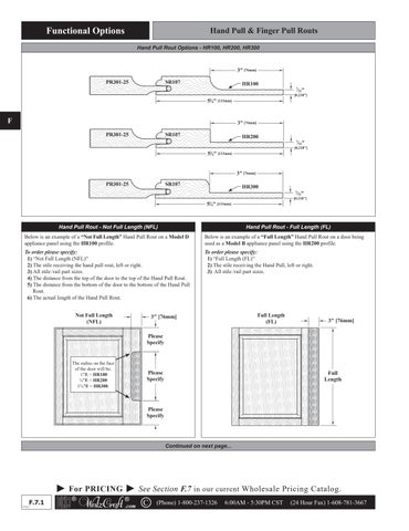
Hand Pull & Finger Pull Routs Hand Pull Rout Options - HR100, HR200, HR300
PR301-25
SR107
HR100
PR301-25
SR107
HR200
PR301-25
SR107
F
HR300
Hand Pull Rout - Not Full Length (NFL)
Hand Pull Rout - Full Length (FL)
Below is an example of a “Not Full Length” Hand Pull Rout on a Model D appliance panel using the HR100 profile.
Below is an example of a “Full Length” Hand Pull Rout on a door being used as a Model B appliance panel using the HR200 profile.
To order please specify: 1) “Not Full Length (NFL)” 2) The stile receiving the hand pull rout, left or right. 3) All stile / rail part sizes. 4) The distance from the top of the door to the top of the Hand Pull Rout. 5) The distance from the bottom of the door to the bottom of the Hand Pull Rout. 6) The actual length of the Hand Pull Rout.
To order please specify: 1) “Full Length (FL)” 2) The stile receiving the Hand Pull, left or right. 3) All stile / rail part sizes.
Not Full Length (NFL)
Full Length (FL)
The radius on the face of the door will be: 1"R = HR100 ¼"R = HR200 1¾"R = HR300.
Continued on next page...
► For PRICING ► See Section F.7 in our current Wholesale Pricing Catalog. F.7.1
V18.2
®
®
.com
C
(Phone) 1-800-237-1326
6:00AM - 5:30PM CST
(24 Hour Fax) 1-608-781-3667
Functional Options
Hand Pull & Finger Pull Routs
Ordering & Pricing Notes: Hand Pull Routs - HR100, HR200, HR300 Ordering Guidelines 1
Please indicate your chosen Hand Pull Rout option (HR100, HR200 or HR300), as well as all information specified in the notes on the previous page, in the Special Instruction area of the order form.
Order Forms
Pricing 1
Pricing
Please see Section F.7 of our current Wholesale Pricing Catalog. Technical Notes: Hand Pull Routs - HR100, HR200, HR300 Cabinet Door & Drawer Front Options (Chapter B)
1
F
Door Styles
A Hand Pull Rout is available on most standard door styles, also Model B and Model D appliance panels.
Typical Part Sizes
A Hand Pull Rout is typically 3" [76.2mm] wide. To maintain a 2¼" [57.2mm] width on the face of the stile, a 5¼" [133.4mm] wide stile is required. Non-standard parts charges may also apply. See Section A.5 for more information.
Sizes / Dimensions 1
Hand Pull Rout Options HR100, HR200, HR300 - END
Hand Pull Rout Options - HR400, HR500 These Hand Pull Rout options are relief cuts that allow additional space behind your hardware for hand clearance.
HR400
HR500
Ordering & Pricing Notes: Hand Pull Routs - HR400, HR500 Ordering Guidelines 1
Order Forms
Applicable order forms will include spaces to indicate your chosen option. Single routs will be centered on the width and height of the drawer front unless otherwise specified.
2
When there are two routs, please indicate the distance from the left edge to center and the distance from the right edge to center in the “Special Instructions” area on the order form, as shown in the drawing above. Routs will be centered on the height of the drawer front unless otherwise specified.
Placement
Pricing 1
Pricing
Please see Section F.7 of our current Wholesale Pricing Catalog. Technical Notes: Hand Pull Routs - HR400, HR500 Cabinet Door & Drawer Front Options (Chapter B)
1
Door Styles
1
Rout Sizes
HR400 and HR500 are available on solid wood and raw MDF slab and RP drawer fronts. Sizes / Dimensions HR400 and HR500 are fixed at the sizes shown in the drawings above. Hand Pull Rout Options HR400, HR500 - END
®
► For PRICING ► See Section F.7 in our current Wholesale Pricing Catalog. ®
.com
C
99.7% American Made
F.7.2
V18.2
Functional Options
Hand Pull & Finger Pull Routs Finger Pull Rout Options - FP100, FP200, FP500
FP100
FP200
FP500
F ** Please refer to the compatibility chart on our Web Site to determine if your choice of outside edge profile accepts a finger pull. ** Full Width Finger Pull and Placement - FP100, FP200, FP500 Please use these abbreviations to specify the placement of the full width finger pull. All finger pulls are viewed from the face of the door or drawer front. Top
T
Bottom
B
Left
L
Right
R
Varies with choice of FP100, FP200 or FP500.
Varies with choice of FP100, FP200 or FP500.
5" Wide Finger Pull and Placement - FP100, FP200, FP500 Please use these abbreviations to specify the placement of the 5" wide finger pull. All finger pulls are viewed from the face of the door or drawer front.
Left
Center
Right
Top
TRL
TRC
TRR
Bottom
BRL
BRC
BRR
Top
Center
Bottom
Left
LST
LSC
LSB
Right
RST
RSC
RSB
Varies with choice of FP100, FP200 or FP500.
Varies with choice of FP100, FP200 or FP500.
Continued on next page...
► For PRICING ► See Section F.7 in our current Wholesale Pricing Catalog. F.7.3
V18.2
®
®
.com
C
(Phone) 1-800-237-1326
6:00AM - 5:30PM CST
(24 Hour Fax) 1-608-781-3667
Functional Options
Hand Pull & Finger Pull Routs Finger Pull Rout Options - FP300, FP400
F
Face View of Door
Face View of Door
FP300 - Horizontal Orientation
FP300 - Vertical Orientation
Please use these abbreviations to specify the placement of the FP300 or FP400 finger pull on your Order Form. All finger pulls are viewed from the face of the door or drawer front. Horizontal Orientation
Face View of Door
Left
Center
FP400 - Horizontal Orientation
FP400 - Vertical Orientation
Right
Top Rail
TRL
TRC
TRR
Bottom Rail
BRL
BRC
BRR
Vertical Orientation
Top
Center
Bottom
Left Stile
LST
LSC
LSB
Right Stile
RST
RSC
RSB
Face View of Door
Continued on next page...
®
► For PRICING ► See Section F.7 in our current Wholesale Pricing Catalog. ®
.com
C
99.7% American Made
F.7.4
V18.2
Functional Options
Hand Pull & Finger Pull Routs Ordering & Pricing Notes: Finger Pull Routs
Ordering Guidelines 1
Order Forms
Applicable order forms will include spaces to indicate your chosen option.
2
Finger Pull Placement
Use charts on the previous pages for abbreviations when specifying placement of your finger pulls on our WalzCraft order forms.
1
Pricing
Please see Section F.7 of our current Wholesale Pricing Catalog.
Pricing
Technical Notes: Finger Pull Routs
F
Cabinet Door & Drawer Front Options (Chapter B, V) 1
Style 1050 / 1050*
Finger pulls are not available at the top or bottom of Style 1050 / 1050* doors and drawer fronts.
2
FP300
Available on Contemporary Slab & Batten doors / Slab & RP drawer fronts (Sections B.9 and B.16).
1
3D Laminate (RTF)
FP500 is the only finger pull rout option available on doors & drawer fronts with 3D Laminate (RTF).
FP300, FP400
Non-standard part sizes may be restricted based on the size and placement of the finger pull. See Section A.5 for more information.
Outside Edge Profiles
Please reference the Outside Edge Profile Compatibility chart on our website under Resources / Technical Information for compatible outside edge profiles.
Finish Options (Chapter R) General Information (Chapter A) 1
Profile Options (Chapter E) 1
Sizes / Dimensions 1
Minimum Width
The minimum width of a door or drawer front with a finger pull on top or bottom is 6" [152.4mm].
2
Minimum Height
The minimum height of a door or drawer front with a finger pull on a side is 6" [152.4mm].
3
Rout Width
When choosing the 5" [127.0mm] wide finger pull option, doors under 7½" [190.5mm] will have the 5" [127.0mm] width reduced, as a 1¼" [31.8mm] minimum space on either side of the finger pull must be maintained. Hand Pull and Finger Pull Routs - END
► For PRICING ► See Section F.7 in our current Wholesale Pricing Catalog. F.7.5
V18.2
®
®
.com
C
(Phone) 1-800-237-1326
6:00AM - 5:30PM CST
(24 Hour Fax) 1-608-781-3667
Functional Options
Your Notes Page 1-800-237-1326
®
www.WalzCraft.com
F
®
®
.com
C
99.7% American Made
F.7.6
V18.2
Functional Options
Finger Pull Moldings - Applied
⅝" [15.9mm] Finger Pull Moldings
PC: AM101 Multiplier: 1.07
PC: AM101 Multiplier: .75
#2241 Molding Application
#2242 Molding Application
PC: AM101 Multiplier: 1.07
F
#2243 Molding Application
Finger Pull Orientation
Top
T
Right
R
Bottom
B
Top & Bottom
T/B
Left
L
Left & Right
L/R
PC: AM101 Multiplier: .70
#2211 Molding Application
Placement Abbreviations
PC: AM101 Multiplier: 1.07
#1804 Molding Application
This drawing not shown at full scale.
PC: AM101 Multiplier: 1.07
#1803 Molding Application
¾" [19.1mm] Finger Pull Moldings
• Please use these abbreviations to specify the placement of applied finger pull molding. • All finger pull moldings are viewed from the face of the door or drawer front.
Ordering & Pricing Notes: Finger Pull Moldings - Applied Ordering Guidelines 1
Order Forms
Applicable order forms will include space to indicate your chosen option(s).
1
Pricing
Please see Section F.8 of our current Wholesale Pricing Catalog.
Pricing
Continued on next page...
► For PRICING ► See Section F.8 in our current Wholesale Pricing Catalog. ®
® .com
C
99.7% American Made
F.8.1
V19.1
Functional Options
Finger Pull Moldings - Applied Technical Notes: Finger Pull Moldings - Applied
Cabinet Door & Drawer Front Options (Chapter B, V)
F
1
#1803, #1804 and #2211 Solid Wood Finger Pull Moldings
Available with: • Style 60 doors & drawer fronts. • Style 2223 Melamine doors and drawer fronts at ¾" nominal thickness. See Melamine Sheet Stock in Section V.4 for exact melamine thicknesses with tolerances. • Style 2224 High Pressure Laminate doors and drawer fronts at ¾" [19.1mm] thick. • Style 500 raw MDF or 3D Laminate (RTF) doors & drawer fronts.
2
#2241, #2242 and #2243 Solid Wood Finger Pull Moldings
Available with: • Style 2223 Melamine doors and drawer fronts at ⅝" nominal thickness. See Melamine Sheet Stock in Section V.4 for exact melamine thicknesses with tolerances. • Style 2224 High Pressure Laminate doors and drawer fronts at ⅝" [15.9mm] thick.
1
Finishing
Applied Finger Pull Moldings are available with all finish options from Chapter R.
Mortise & Tenon
A mortise & tenon joint is used to connect the finger pull molding to the door or drawer front. The mortise and the tenon both stop ½" from each edge of the door, thus concealing the joint and preventing it from being seen once the finger pull molding is applied.
Finish Options (Chapter R)
Functional Options (Chapter F) 1
Molding Options (Chapter N) 1
8' [2438.4mm] Lengths
These moldings are also available in 8' [2438.4mm] lengths. See Section N.9. Finger Pull Moldings - Applied - END
► For PRICING ► See Section F.8 in our current Wholesale Pricing Catalog. F.8.2
V19.1
®
® .com
C
(Phone) 1-800-237-1326
6:00AM - 5:30PM CST
(24 Hour Fax) 1-608-781-3667
Functional Options
Drawer Front Scoops Drawer Front Scoop Options SC100
Drawer Front Scoop Option
SC200
Drawer Front Scoop Option
F
Ordering & Pricing Notes: Drawer Front Scoops Ordering Guidelines 1
Order Forms
Please use “Advanced Version” of the Drawer Front Order Form (E•Z Form #3).
1
Pricing
Please see Section F.9 of our current Wholesale Pricing Catalog.
Pricing
Technical Notes: Drawer Front Scoops Cabinet Door & Drawer Front Options (Chapter B, V) 1
Drawer Front Styles
Available with the following drawer front styles: 34SQA*, 100SQE*, 1270*, 500*.
1
Convex / Concave
Drawer front scoops are available with convex / concave drawer fronts.
Convex / Concave Options (Chapter D) Finish Options (Chapter R) 1
3D Laminate (RTF)
Style 500* drawer fronts with SC100 and SC200 are available with all 3D Laminate (RTF) patterns. Profile Options (Chapter E) Solid wood and raw MDF drawer fronts with scoops are available with all outside edge profiles from Section E.15. • The indicates outside edge profiles that are available on products using 3D Laminate (RTF).
1
Outside Edge Profiles
Profile is applied last so it will follow the shape of the scoop. When needed please see our Profile Reveal Width chart on our website under Resources > Technical Information to see outside edge profile widths. Sizes / Dimensions
1
Drawer Front Scoop Option SC100 is 527/32"W x ⅞"H [148.6mm x 22.2mm].
Scoop Dimensions
Drawer Front Scoop Option SC200 is 8"W x 2"H [203.2mm x 50.8mm]. SC100: Minimum drawer front width is 8" [203.2mm] + (profile width x 4). Minimum drawer front height is 3" [76.2mm] + (profile width x 2).
2
Minimum Drawer Front Size
SC200: Minimum drawer front width is 10" [254.0mm] + (profile width x 4). Minimum drawer front height is 3" [76.2mm] + (profile width x 2). See Profile-Reveal Widths chart on our website: Resources / Technical Information. Drawer Front Scoops - END
®
► For PRICING ► See Section F.9 in our current Wholesale Pricing Catalog. ®
.com
C
99.7% American Made
F.9.1
V18.2
Functional Options
Dowel Hole Patterns Dowel Hole Patterns
DHP1
Dowel Hole Pattern
F
5mm Diameter Holes x 12.7mm Deep
DHP2
Dowel Hole Pattern
5mm Diameter Holes x 12.7mm Deep
Continued on next page...
► For PRICING ► See Section F.10 in our current Wholesale Pricing Catalog. F.10.1
V18.2
®
®
.com
C
(Phone) 1-800-237-1326
6:00AM - 5:30PM CST
(24 Hour Fax) 1-608-781-3667
Functional Options
Dowel Hole Patterns Ordering & Pricing Notes: Dowel Hole Patterns Ordering Guidelines 1
Order Forms
Please indicate DHP1 or DHP2 in the Special Instructions column on your door or drawer front order form.
1
Pricing
Please see Section F.10 of our current Wholesale Pricing Catalog.
Pricing
Technical Notes: Dowel Hole Patterns Cabinet Door & Drawer Front Options (Chapter B) 1
Available Styles
Available with all door and drawer front styles with the exception of Contemporary Slab & Batten doors, and molded drawer fronts.
1
Hinge Boring
Hinge boring is not compatible with dowel hole patterns.
1
Ready to Assemble
Doors and drawer fronts with dowel hole patterns are not available Ready to Assemble (RTA).
2
Warranties
Please see Section A.8 - Warranties for more information on Glued-Up Panel expansion/contraction, warping, bowing and twisting.
Outside Edge Profiles
Available with all outside edge profiles from Sections E.15 and E.16. • Also available with Molder Edge (ME) profiles from Section E.9.
F
Functional Options (Chapter F) General Information (Chapter A)
Profile Options (Chapter E) 1
Available with all Traditional stile & rail profiles from Sections E.1, E.2, and E.3. 2
Stile & Rail Profiles
Available with most MP600 / MP6000, MP700, and MP900 miter profiles from Sections E.9, E.10, and E.11. • Compatibility will be reviewed at the time you place a quote or an order.
3
Nexus Profiles
Available with all nexus profiles with the exception of NP407.
4
Center Panel Profiles
Available with all center panel profiles from Sections E.12, E.13, and E.14.
5
RP (Raised Panel) Profiles
Available with most RP (Raised Panel) drawer front profiles from Section B.16. • Compatibility will be reviewed at the time you place a quote or an order.
1
Sheet Stock
For sheet stock items with dowel hole patterns, please order as Style 60 doors or drawer fronts from Sections B.10 or B.11.
Available with all applied molding stile & rail profiles from Sections E.4, E.5, and E.6.
Sheet Stock Options (Chapter K) Sizes / Dimensions Minimum height for any product receiving DHP1 is 329/32" [99.0mm].
1
Minimum Height
2
Maximum Height
Maximum height for any product receiving DHP1 or DHP2 is 591/16" [1500.0mm].
3
Minimum Width
Minimum width for any product receiving DHP1 or DHP2 is 6" [152.4mm].
4
Maximum Width
Maximum width for any product receiving DHP1 or DHP2 is 36" [914.4mm].
5
Thicknesses
All material 5/8" [15.9mm] thick or greater can receive DHP1 or DHP2.
6
Minimum Stile Width
Minimum width for any stile receiving DHP1 or DHP2 is 2" [50.8mm].
Minimum height for any product receiving DHP2 is 921/32" [245.0mm].
Dowel Hole Patterns - END
®
► For PRICING ► See Section F.10 in our current Wholesale Pricing Catalog. ®
.com
C
99.7% American Made
F.10.2
V18.2
Functional Options
Your Notes Page ®
1-800-237-1326
www.WalzCraft.com
F
F.10.3
V18.2
®
®
.com
C
(Phone) 1-800-237-1326
6:00AM - 5:30PM CST
(24 Hour Fax) 1-608-781-3667