

LOUDOUN COUNTY PUBLIC SCHOOLS
VIEW TRANSITION
ACADEMY
SCHEMATIC DESIGN REPORT
JANUARY 21, 2026





PROJECT TEAM
PROJECT TEAM
Architect
VLK
4200 Wilson Blvd Ste 501 Arlington, VA 22203 703-636-6071
Principal-in-Charge/PM
Project Architect
Planner
Civil Engineer
Urban Engineering
7712 Little River Turnpike Annandale, VA 22003 703-642-8080
Matt Waguespack* mwaguespack@vlkarchitects.com 571-291-5828
Theresa Mozinski tmozinski@vlkarchitects.com 920-645-5893
Derk Jeffrey djeffrey@vlkarchitects.com 571-235-2562
Principal Chris Myers* cmyers@urban-ltd.com 703-642-8080
Project Manager
MEPT Engineer
James Posey Associates 11155 Red Run Boulevard, Suite 310 Baltimore, MD 21117 410-265-6100
Vice President Justin Bem* jbem@jamesposey.com 443-279-8300
Electrical Project Manager
Ben Meister** bmeister@jampesposey.com 410-265-6100
Mechanical/Plumbing Project Manager Kyle Pepperman** kpepperman@jamesposey.com BIM Jesse Carey jcarey@jamesposey.com
Structural Engineer
Bennett & Pless 46090 Lake Center Plaza Ste 308 Potomac Falls, VA 20165 571-323-0320
Project Manager
Robert Schottler* rschottler@bennett-pless.com 571-503-9571
Project Engineer Chungfu Yang** cyang@bennett-pless.com BIM Katie Herrera kherrera@bennett-pless.com
PROJECT TEAM
Food Service
Nyikos Garcia Food Service Design 7146 Starmount Way New Market, MD 20879 240-683-9530
Principal Jay Garcia* jgarcia@nyikosgarcia.com
240-464-8280 Project Manager/BIM Gene Sabalboro gsabalboro@nyikosgarcia.com 240-683-9530
Acoustics
Miller, Beam & Paganelli 12040 South Lakes Drive Reston, VA 20191 703-506-0005
Senior Acoustical Consultant
Cost Estimating
Downey & Scott 6799 Kennedy Road, Unit F Warrenton, VA 20187 540-347-5001
Kelton Mitchell* kmitchell@millerbp.com
703-506-0005
Sr. Cost Estimator Joe Adams* jadams@downeyscott.com 540-347-5001 Project Manager David Repass drepass@downeyscott.com 540-347-5001 x111
Sustainability
Sustainable Building Partners 2701 Prosperity Ave, Ste 100 Fairfax, VA 22031 703-970-2890
Director Rachel Nicely** rachel.nicely@sustainbldgs.com 703-712-6626 Program Manager Neha Vyas* neha.vyas@sustainbldgs.com 703-713-5124
*indicates primary point of contact **indicates secondary copy where applicable
02
PROJECT SCHEDULE
PROJECT SCHEDULE
DESIGN:
SD Submission
DD Submission
65% CD Submission
100% CD Submission
Bid Set
BID:
Issue for Bids
Receive Bids
Contract Award
CONSTRUCTION
Notice to Proceed
Substantial Completion
CMPT (see detailed Civil schedule):
1st Submission
Checklist Submission
Acceptance
1st Submission Comments
2nd Submission
2nd Submission Comments
Planning Commission
Board of Supervisors
STPL (see detailed Civil schedule):
1st Submission
1st Submission Comments
January 21, 2026 (12 weeks)
April 15, 2026 (12 weeks)
June 24, 2026 (10 weeks)
August 19, 2026 (8 weeks)
September 16, 2026 (4 weeks)
September 16, 2026
October 14, 2026
November 2026
December 2026
December 2026 – mid-May 2028 (18 months)
November 2025
December 2025
December 2025
February 2026 = 60-day review
March 2026
May 2026
June 2026
July 2026
February 2026
April 2026
2nd Submission May 2026
2nd Submission Comments
3rd Submission
Approval
June 2026
July 2026
October 2026
Grading Plan Approval Letter Issued October 2026
round of CMPT comments issued)
NARRATIVES
ARCHITECTURAL
General Description
The VIEW Transition Academy is a comprehensive facility dedicated to supporting students with disabilities through specialized programming in Career and Technical Education (CTE) and independent living skills. Designed to serve high school students up to age 22, the center will also provide career exploration opportunities for middle school students prior to their transition to high school. The new facility will have a capacity of 290 students and approximately 86 staff. In addition to standard educational components such as administrative offices, food service areas, and traditional classrooms, the program includes 15 Career and Technical Education (CTE) pathway labs and a dedicated independent living lab to support specialized instruction and workforce readiness.
The new Transition Center will be located at the former Aldie Elementary School site at 24328 Marrwood Drive in Aldie, VA. The site features a generally flat topography with a gradual slope toward the rear. The existing building is 42,777 sf and consists of a steel-framed structure offering optimal flexibility for renovation.
The proposed design includes 34,835 sf renovation (7,942 sf of the existing building will be demolished) and 31,100 sf of addition for a total gross floor area of 65,935 sf. The total building area per Loudoun Zoning definition is 63,634 sf (measured to inside face of wall) which is under the maximum floor area of 63,744 sf per the FAR.
Accessibility
The VIEW Transition Academy will be fully accessible to individuals with disabilities. Due to existing site grades, there is a two-foot elevation difference between the existing building and the new addition. This floor elevation change will be accommodated by a wide, 1:12 ramp as illustrated on the plans.
Life Safety
• Type IIB, Use Group E
o No firewalls are required since the total SF is under the allowable area factor (including frontage increase)
• Automatic Fire Suppression System
Applicable Building Codes
The VIEW Transition Academy design will comply with the following codes as adopted by Loudoun County Building & Development:
• 2021 Virginia Uniform Statewide Building Code
• 2017 Accessible and Usable Buildings and Facilities (ICC/ANSI A117.1)
• 2021 National Electric Code (NFPA 70)
• 2021 Virginia Plumbing Code
• 2021 Virginia Mechanical Code
• 2021 Fuel Gas Code
• 2021 Virginia Statewide Fire Prevention Code
• 2021 Virginia Energy Conservation Code
Exterior Envelope
1. Renovation
a. Exterior Walls
b. Roof
i. Typical Existing Condition:
1. 4” CMU, 2” cavity insulation, and 4” brick veneer up to 10’-0” (16’-0” at high roof).
2. Corbeled brick with 1” interior insulation above 10’-0” (above 16’-0” at high roof).
3. Brick with no CMU/insulation at piers
ii. New Scope of Work
1. Existing composite CMU/brick wall to remain up to 10’-0”
2. Demo corbeled brick above 10’-0” (above 16’-0” at high roof).
3. Demo brick at piers
4. Provide new 3” spray foam insulation/air barrier (R21), cavity space, and brick veneer or metal panel (see elevations) at all existing exterior walls
i. Typical Existing Condition:
1. 3” lightweight concrete, 1 7/8” insulation, built-up roofing, and gravel ballast
ii. New Scope of Work
1. Existing 3” lightweight concrete to remain.
2. Demo insulation, built-up roofing, and gravel ballast.
3. Provide new 5-inches polyisocyanurate insulation (R30 CI), coverboard, and white fully adhered EPDM membrane
c. Windows
i. Typical Existing Condition
1. Aluminum windows and storefront with 1” insulated glass
ii. New Scope of Work
1. Demo all existing windows and storefront.
2. Provide new thermally broken aluminum windows with double pane, insulating, low E glass (BOD: Solarban 90).
2. Addition
a. Exterior Walls
i. Masonry Veneer on CMU Back-up
1. CMU back-up, 3” spray foam insulation/air barrier (R21), cavity space, masonry veneer
ii. Metal Panel on CMU Back-up
1. CMU back-up, 3” spray foam insulation/air barrier (R21), hat channels, single skin metal panel
b. Roof
i. Steel deck, 5-inches polyisocyanurate insulation (R30 CI), coverboard, and white fully adhered EPDM membrane.
c. Windows
i. Thermally broken aluminum windows with double pane, insulating, low E glass (BOD: Solarban 90)
Interior Construction
1. Interior Partitions
a. CMU – painted
i. Typical UON
b. Metal Stud with Gyp Board – painted
i. Administration
c. Ceramic Tile Wainscot (to 7’-4” high) with Epoxy Paint Above
i. Toilet Rooms
2. Floors
a. Powerbond Carpet
i. Administration
ii. Conference Rooms
iii. Lounge
iv. Collaboration
b. Resilient Flooring (VCT)
i. Classrooms
ii. Cosmetology
iii. Digital Lab
iv. Safety & Security
v. Hospitality
vi. Workroom
vii. DDI
viii. IFT
c. Polished Concrete
i. Makerspace
ii. Animal Care
iii. Skilled Trades
iv. Automotive
v. Landscaping/Hardscaping
vi. Horticulture
vii. Greenhouse
d. Rubber Athletic Flooring
i. Fitness
e. Ceramic Tile (2 x 2 Keystones Mosaic)
i. Toilet Rooms
f. Resinous Flooring (Dur-a-flex Polycrete SLB)
i. Kitchen
g. Epoxy Floor Paint
3. Wall Base
i. Mechanical, Electrical, MDF, IT, Custodial Rooms
a. 4” Rubber
i. Typical UON
b. Ceramic Tile 2 x 2 Cove Base
i. Toilet Rooms
c. Porcelain Cove Base
i. Corridors
4. Ceilings (See sheet A901)
a. 2 x 2 Lay-in Acoustical Tile
i. Typical UON
b. 2 x 2 Lay-in Vinyl Faced Acoustical Tile
i. Toilet Rooms
ii. Kitchen
iii. Culinary Lab
c. 2 x 4 Lay-in Acoustical Tile (Staggered)
i. Multi-Purpose Room
ii. Career Center
d. Acoustic Baffles
i. Dining, Lounge, Collaboration
e. Linear Metal Ceiling
i. Main Entrance
f. Exposed Structure with 2” Acoustical Spray on Metal Deck
i. Animal Care
ii. Skilled Trades
iii. Automotive
iv. Landscaping/Hardscaping
v. Horticulture
vi. Makerspace
g. Exposed Structure
i. Mechanical, Electrical, MDF, IT, Custodial Rooms
ii. Receiving
iii. Greenhouse
5. Doors and Frames
a. Doors - Particle Core with Wood Veneer
b. Frames – Hollow Metal – painted
6. Casework
a. Plastic Laminate Casework with Solid Surface Countertop
i. Typical UON
STRUCTURAL
Structural Systems – Existing
The building was originally constructed in the 1970s. Based on the existing structural drawings prepared by William J. Davis Consulting Engineers dated August 2, 1972, and a site survey made by our office on November 11, 2025, the construction consists of a single-story steel-framed structure with infilled masonry walls. The existing roof is a ballasted roof that comprises of 3” lightweight concrete fill on top of the steel roof deck, which spans to open-web steel joists supported by wide-flange steel girder beams. The exterior walls consist of 4” brick and 4” CMU with rigid insulation between the wythes. The CMU and brick are tied together with masonry ties so that the CMU and brick act together to withstand the wind loads. The wide-flange beams are supported by steel columns. The columns are supported on isolated spread footings with reinforced concrete piers. Floor construction at grade consists of 4" thick concrete slabs-on-grade reinforced with welded wire fabric.
Structural Systems – Addition
1. Foundations and Slab-on-Grade
A site-specific geotechnical investigation will be needed to provide recommendations for the foundation system. The foundation system selected will be based on the anticipated building loads and soil conditions encountered. The final design will be based upon the soil recommendations for design parameters, site preparation, slab-on-grade support, compaction and backfill, and retaining wall pressures
The typical slab-on-grade will be 4” thick normal weight concrete over a 15-mil vapor barrier on a 4” well-compacted granular material conforming to an open graded aggregate gravel base (such as VDOT No. 57 stone). The 4” slab-on-grade will be reinforced with 6x6-W2.1xW2.1 welded wire fabric. At the kitchen, storage rooms, mechanical and electrical room, the slabs-on-grade will be 5” thick normal weight concrete reinforced with 6x6- W2.9xW2.9. Control joints will be located in the slab, with spacing of joints not to exceed 12’-0” on center.
Isolated footings will be located below all steel columns. Interior column footings will be 6’-0” x 6’0” x 1’-2” or 5’-0” x 5’-0” x 1’-0”, and exterior column footings will be 4’-0” x 4’-0” x 1’-0”, assuming an allowable soil bearing pressure of 3,000 psf referenced in the existing structural drawings Continuous 2’-0” x 1’-0” wall footings will be located below exterior CMU walls.
At the perimeter of the building, the top of footings will be located 2’-0” from the top of the building slab for frost protection. At the exterior steel columns, concrete encasement will be provided.
2. Roof Framing
The typical roof framing will consist of 1½” x 20 gage wide rib galvanized metal roof deck spanning to open-web K-series steel bar joists spaced 5’-0” on center maximum. Tighter spacing or KCS joists will be required in areas with additional snow drift and mechanical roof top equipment. The bar joists will span to wide flange girder beams supported by tube steel columns. See the conceptual roof framing layout plans for joist span directions and estimated depths, column lines, and estimated beam/girder sizes.
3. Lateral Force Resisting System
Ordinary steel moment frames will be utilized for the required wind and seismic lateral load resistance. There will be 1½” expansion joints separating the addition from the existing building.
Codes and Standards
The VIEW Transition Academy design will comply with the following codes as adopted by Loudoun County Building & Development:
Primary References
• Virginia Uniform Statewide Building Code 2021 (USBC)
• International Building Code 2021 with Local Amendments
• International Existing Building Code 2021 with Local Amendments
• American Society of Civil Engineers: Minimum Design Loads for Buildings and Other Structures (ASCE/SEI 7-22)
• American Concrete Institute: Building Code Requirements for Reinforced Concrete (ACI 318-19)
• Building Code Requirements and Specification for Masonry Structures (TMS 402- 16/ACI 53016/ASCE 5-16)
• American Institute for Steel Construction: Steel Construction Manual 15th ed. (AISC 360-16)
Other Referenced Organizations
• American National Standards Institute (ANSI)
• American Iron and Steel Institute (AISI)
• American Society for Testing and Materials (ASTM)
• Portland Cement Association (PCA)
• Concrete Reinforcing Steel Institute (CRSI)
• American Welding Society (AWS)
• National Concrete Masonry Association (NCMA)
• Brick Institute of America (BIA)
Design Loads and Criteria
1. Risk Category III
2. Superimposed Dead Loads
a. Mechanical, Electrical, and Plumbing Systems
b. Sprinkler System
c. Suspended Ceiling
d. Roofing and Insulation
e. Future Solar Allowance 10 psf
3. Live Loads
a. Classrooms 40 psf + 15 psf partition load
b. Office Space 50 psf + 15 psf partition load
c. Toilet Rooms
d. First Floor Slabs-on-Grade
e. Stairs
f. Light Storage Rooms
g. Mechanical and Electrical Rooms
h. Roof
psf
psf
psf
psf min. Drifting, sliding and unbalanced snow loads will be considered in the design.
4. Snow Loads
a. Importance Factor, I s 1.10
b. Ground Snow Load, Pg 95 psf
c. Exposure Factor, Ce 1.0
d. Thermal Factor, Ct 1.2 (Assumed)
e. Flat Roof Snow Load, Pf 66 psf
5. Wind Loads
a. Ultimate Wind Speed, VULT 120 mph (3 Sec. Gust)
b. Nominal Wind Speed, VASD 93 mph (3 Sec. Gust)
c. Exposure C
d. Internal Pressure Coefficient ±0.18
6. Seismic Design Criteria
a. Seismic Importance Factor 1.25
b. Spectral Response Coefficients
TBD by Geotech. Study
c. Site Class D (Assumed)
TBD by Geotech. Study
d. Seismic Design Category A (Assumed)
TBD by Geotech. Study
7. Roof Rain Load
a. Rain Intensity (15-Minute) 6.32 in/hr
8. Flood Zone Categorization X (unshaded)
9. Tornado Wind Load
a. Tornado Speed, VT 50 mph Tornado Design Not Req’d
10. Deflection Criteria
a. Total building drift will be limited to H/400 for lateral loads.
b. Roof framing will be limited to a live load deflection of L/360.
Construction Materials
1. Concrete (Minimum Strength of Normal Weight Concrete at 28 Days)
a. Footings f’c = 3,000
b. Int. Slab-on-Grade f’c = 3,000
c. Ext. Walls/Piers Exposed to Weather f’c = 4,500
d. Ext. Slab-on-Grade f’c = 4,500
2. Reinforcing Steel
a. Reinforcing Bars
b. Welded Wire Fabric
3. Structural Steel
a. Wide Flange Shapes and Channels (W, C, MC)
b. Misc Shapes (M, S, L), Plates and Bars
c. Square/Rectangular Tubing (HSS)
d. Round Tubing (HSS)
e. Structural Pipe
f. Structural Bolt
g. Structural Nut
h. Structural Washers
i. Anchor Rods
j. Metal Deck
ASTM A615, Fy = 60 ksi
ASTM A185
ASTM A992, Fy = 50 ksi
ASTM A572, Fy = 50 ksi
ASTM A500 Gr. C, Fy = 50 ksi
ASTM A500 Gr. C, Fy = 50 ksi
ASTM A53 Gr. B, Fy = 35 ksi
ASTM A325 or A490
ASTM A563
ASTM F436
ASTM F1554 Gr.55/S1
ASTM A653, Fy = 50 ksi
k. Welding Electrodes E70XX
4. Masonry
a. Hollow Concrete Units
b. Mortar
c. Grout
5. Special Requirements
ASTM C90, f'm = 2,000 psi
ASTM C270, Type 'S’
ASTM C476, 2,000 psi
a. All exposed structural steel, including lintels in exterior walls, shall be hot-dipped galvanized
b. Concrete exposed to weather will have air entraining admixtures
c. Concrete for slabs and pumped concrete will have high range water reducing and superplasticizers added to them.
Pre-Engineered Systems
• Structural Steel Connections
• Open-Web Steel Bar Joists
• Greenhouse
• Steel Stairs, Railings, Connections, and Ladders
• Cold-Formed Metal Framing
• Canopies
• Skylights
MECHANICAL
APPLICABLE CODES AND STANDARDS
• 2021 Virginia Uniform Statewide Building Code (VUSBC) (2021 IBC Amended)
• 2021 Virginia Mechanical Code (2021 IMC Amended)
• 2021 Virginia Energy Conservation Code (2021 IECC Amended)
• 2021 Virginia Plumbing Code (2021 IPC Amended)
• 2021 Virginia Statewide Fire Prevention Code (2021 IFC Amended)
• 2021 Virginia Fuel Gas Code (2021 IFGC Amended)
• ASHRAE Standard 55-2010 - Thermal Environmental Conditions for Human Occupancy
• ASHRAE Standard 62.1-2010 - Ventilation for Acceptable Indoor Air Quality
• ASHRAE Standard 90.1-2010 - Energy Standard for Buildings
• NFPA 13: Standard for the Installation of Sprinkler Systems, latest edition
• NFPA 90A: Standard for the Installation of Air Conditioning and Ventilating Systems, latest edition
• American Society of Heating, Refrigerating and Air-Conditioning Engineers (ASHRAE), Handbooks
DESIGN STANDARDS
HVAC system design will be based on the following conditions:
1. Outdoor Design Temperatures
a. Summer: 95°F (Dry Bulb) / 78 °F (Wet Bulb)
b. Winter: 0°F DB
2. Indoor Design Temperatures
a. Occupied Cooling Setpoint: 73°F DB / 50% Relative Humidity (Maximum)
b. Occupied Heating Setpoint: 71°F DB
c. Unoccupied Heating Setpoint: 55°F DB
d. Unoccupied Cooling Setpoint: 85°F DB
e. Utility Spaces (Mechanical and Electrical Rooms, etc.): 60°F DB Heating
3. Building Occupancy Densities
a. Architectural Furnishing Plans
b. Estimated Maximum Occupancy Densities Provided in IMC Chapter 4
4. Ventilation Rates
a. Minimum Ventilation Rates: IMC Chapter 4 and ASHRAE Standard 62.1-2022
b. Ceiling Supply Air Systems: 0.8 to 1.0 Ez (Zone Air Distribution Effectiveness)
EXISTING BUILDING SYSTEMS
The existing mechanical infrastructure consists mainly of variable volume and temperature (VVT) systems. The VVT systems include packaged rooftop heat-pump units and VVT zone dampers. The packaged rooftop units include heat pump refrigeration systems with auxiliary electric heating coils. Existing building systems were installed as part of a 2007 building renovation. All existing systems are nearing the end of their service life and do not meet today’s standards for temperature control, comfort and energy efficiency. As part of the scope of this project, all existing mechanical systems will be removed.
1. Classroom and Administration Areas – Served by a total of nine VVT systems.
2. Multipurpose Room – Space conditioning is provided by two single-zone packaged rooftop units. Each packaged rooftop unit includes a cooling-only refrigeration system and auxiliary electric heating coils.
3. Kitchen – Space conditioning is provided by a single-zone packaged rooftop heat-pump unit. The
unit includes heat-pump refrigeration and auxiliary electric heating coils.
PROPOSED MECHANICAL SYSTEMS
The heating, ventilation and air conditioning systems will be designed based on the criteria set forth in the 2021 Virginia Uniform Statewide Building Code. The design will adhere to the LCPS High School Technical Specification, latest edition. The design will meet the requirements to obtain LEED V4 certification.
Space conditioning and ventilation air will be provided throughout the building via a series of multi-zone and single-zone variable air volume systems. Anticipated system components including the following:
1. Provide new packaged rooftop air-source heat pump units with DX heating and coil cooling, hot gas reheat coil for dehumidification control, and auxiliary indirect gas-fired heating coil for use during low ambient conditions and during defrost operation. The heat pump unit will include a power exhaust fan to accommodate airside economizer operation. Additionally, the heat pump unit will include an enthalpy wheel energy recovery device to pre-condition outdoor air.
2. New supply air distribution ductwork with ceiling-mounted supply air devices.
3. New return air distribution ductwork. Return air devices will be positioned low within the occupied spaces where possible.
4. Multi-zone systems will include supply air terminal units (VAV boxes) with electric heating coils to provide zone temperature control to each space served.
The system design will require approximately 17 packaged rooftop heat pump units (RTU’s) due to the space limitations within the existing structure and ceiling height concerns. The smaller RTU sizing will limit the size of the equipment on the roof as well as the size of the main distribution ductwork. Singlezone VAV systems enable for individual space temperature and dehumidification control to be provided without the need for excessive re-heat energy.
1. CTE Lab spaces: Space conditioning and ventilation will be provided by single-zone, VAV packaged rooftop units with DX air-source heat-pumps and auxiliary indirect gas-fired heating coil. RTU supply and power exhaust fans will be equipped with variable frequency drives for reducing airflow quantities during periods of reduced cooling demand. All RTU’s will be provided with demand control ventilation, energy recovery and equipped with airside economizer, providing free cooling during periods of reduced outdoor temperatures.
2. Multipurpose Dining Area: Space conditioning and ventilation will be provided by a single-zone, VAV packaged rooftop unit with DX air-source heat-pump and auxiliary indirect gas-fired heating coil. RTU supply and power exhaust fans will be equipped with variable frequency drives for reducing airflow quantities during periods of reduced cooling demand. The RTU will be provided with demand control ventilation, energy recovery and equipped with airside economizer, providing free cooling during periods of reduced outdoor temperatures.
3. Classrooms: Space conditioning and ventilation will be provided via a series of VAV rooftop units, with DX air-source heat pumps and auxiliary indirect gas-fired heating coils. VAV terminal units with electric heating coils will provide space temperature control. Rooftop units supply and return fans will be equipped with variable frequency drives for reducing airflow quantities during periods of reduced cooling demand. The rooftop units will be provided with energy recovery wheels for preconditioning the outside air and airside economizer, providing free cooling during periods of reduced outdoor temperatures.
4. Administration area: Space conditioning and ventilation will be provided by a VAV rooftop unit, with DX air-source heat pump and auxiliary indirect gas-fired heating coil. VAV terminal units with electric heating coils will provide space temperature control. The rooftop units supply and return
fans will be equipped with variable frequency drives for reducing airflow quantities during periods of reduced cooling demand. The rooftop unit will be provided with an energy recovery wheel for preconditioning the outside air and airside economizer, providing free cooling during periods of reduced outdoor temperatures. Providing a dedicated RTU allows for summertime operation of the Administration wing while the rest of the building is operating at set-back temperatures.
Per the Code of VA Industry-recognized uniform inspection law, the systems proposed will be equipped with the necessary features and equipment to perform the required inspections and evaluations. Airflow measuring stations will be integrated into all proposed systems and equipment to allow LCPS to perform the required measurements and verify outdoor airflow rates.
Unoccupied areas with exterior exposure such as storage, restrooms, vestibules, mechanical and electrical rooms will be heated via electric resistance cabinet and propeller unit heaters.
All toilet rooms, janitor closets, utility rooms and storage areas will be provided with mechanical means of exhaust.
Special exhaust systems will be provided as required for all CTE spaces.
IT network and data rooms that house equipment producing relatively high internal heat gain will be conditioned via a DX air-cooled heat pump units. Associated outdoor condensing unit will be located on the roof.
Dry Food Storage located within the Kitchen area will be conditioned via a DX air -cooled heat pump unit. The associated outdoor condensing unit will be located on the roof.
Controls:
1. A new building automation system will be provided to monitor and control the new HVAC equipment. The system will be installed in accordance with the Loudon County Public Schools standards and networked to the existing LCPS Facilities EMS. Actuation will be electric/electronic for all systems. All equipment will be provided with BACnet protocol for interface with building automation system. The DDC system will allow for general trending to assist with detecting problems and potentially resolving them without requiring access to the school facility.
ENVIRONMENTAL CONSERVATION STATEMENT
Energy and water conversation are fundamental aspects of sustainable building design. The VIEW Transition Academy is being designed to achieve LEED Silver certification. The following energy and water conservation strategies will be incorporated into the project to support the LEED certification goal.
• Mechanical systems will exceed the energy efficiency requirements mandated by the 2021 Virginia Energy Conservation Code
• Energy recovery will be used to pre-condition outdoor ventilation air where appropriate and permitted by IMC requirements.
• Premium efficiency and electronically commutated (EC) type motors will be specified for all fan systems.
• Heat pump units will utilize two-stage compressor technology with EC fan motors for improved heating and cooling efficiencies.
• Systems delivering ventilation airflow will include MERV 13 filtration to improve indoor air quality and meet LEED indoor air quality recommendations.
• Mechanical systems will be designed to maximize indoor air quality by effectively mixing and delivering fresh air to building occupants.
• Demand control ventilation is anticipated throughout high-occupancy building areas to monitor room carbon dioxide levels and automatically adjust the quantity of outdoor air supplied to each space.
• Environmentally friendly refrigerants will be specified for mechanical equipment.
• The HVAC system will be controlled by building automation system for remote monitoring and energy management.
• The HVAC system will be divided into multiple zones of operation for efficient year -round and after-hours usage.
• Specifications will exclude materials that lead to poor indoor air quality.
APPLICABLE CODES AND STANDARDS
• 2021 Virginia Uniform Statewide Building Code (VUSBC) (2021 IBC Amended)
• 2021 Virginia Plumbing Code (2021 IPC Amended)
• 2021 Virginia Fuel Gas Code (2021 IFGC Amended)
PLUMBING SYSTEMS
1. Domestic Water Piping Systems
The existing incoming water service will be removed and replaced under the scope of this project. The existing electric water heater will be replaced with three heat-pump style electric water heaters complete with circulation pump, expansion tank and thermostatic mixing valve. 140 degrees F hot water will be supplied to the kitchen area, with 110 degrees F supplied to plumbing fixtures throughout the remaining portions of the school.
2. Storm Water Piping Systems
The existing storm water piping components, including roof drains, overflow drain, and abovegrade storm water piping systems will be removed and reconfigured to accommodate the building addition and renovation. Above and below grade piping systems will be constructed from PVC material.
3. Sanitary and Vent Piping Systems
Portions of the existing sanitary and vent piping systems throughout the school will be removed and reconfigured to accommodate the building addition and renovation. New sanitary and vent piping will be provided for supporting new plumbing fixtures as required by the architectural modifications. Above- and below-grade sanitary and vent piping systems will be constructed from PVC material. Vent piping will terminate at the roof level, with a minimum 25-foot separation provided between vent piping terminations and any outdoor air intake locations. Sanitary piping systems will connect to existing building systems located below the slab where possible. Sanitary waste from the Kitchen area will discharge to a new grease interceptor located below grade near the new loading dock service area.
4. Natural Gas Piping Systems
A new 2 PSI gas service will be provided to the building. Gas piping will serve the new packaged rooftop units auxiliary heating coils and new kitchen equipment.
5. Plumbing Fixtures
Institutional grade plumbing fixtures will be provided. These fixtures will include wall-hung water closets utilizing 1.28 gallon per flush valves, pint flush (0.125 gallon per flush) wall-hung urinals, and wall-hung lavatories with self-closing hot- and cold-water faucets that supply 0.50 gallons per minute. All plumbing fixtures will comply with the Americans with Disabilities Act (ADA).
ENVIRONMENTAL CONSERVATION STATEMENT
Energy and water conversation are fundamental aspects of sustainable building design. The VIEW Transition Academy is being designed to achieve LEED Silver certification. The following energy and water conservation strategies will be incorporated into the project to support the LEED certification goal.
• Plumbing systems will exceed the energy efficiency requirements mandated by the 2021 Virginia Energy Conservation Code
• Domestic water heaters will utilize heat pumps for improved heating efficiency.
• Premium efficiency and electronically commutated (EC) type motors will be specified for all pumping systems.
• Low-flow fixtures will be specified to reduce overall building water consumption. Specific strategies will include low-flow flush valves, low-flow aerators and self-closing faucets.
• The plumbing system design will include a building-level water meter, enabling monitoring of total building water usage.
APPLICABLE CODES AND STANDARDS
• 2021 Virginia Uniform Statewide Building Code (VUSBC) (2021 IBC Amended)
• 2021 Virginia Plumbing Code (2021 IPC Amended)
• 2021 Virginia Statewide Fire Prevention Code (2021 IFC Amended)
• NFPA 13: Standard for the Installation of Sprinkler Systems, latest edition
• NFPA 70: National Electrical Code (NEC), latest edition
• NFPA 72: National Fire Alarm and Signaling Code, latest edition
• NFPA 101: Life Safety Code, latest edition
FIRE SUPPRESSION SYSTEMS
1. The existing building is not currently provided with a fire suppression system.
2. Based on the flow test dated 11/24/2025, it is anticipated that a fire pump will not be required.
3. A new incoming fire service main will be provided with a double-check type backflow preventer upon entry into the building. A fire department connection (FDC) will be provided along the front face of the building within 100 feet of a paved fire department access road.
4. Sprinklers will be quick response, semi-recessed, fusible link type and installed symmetrically with the ceiling layout. Finished brass sprinklers will be provided in normally occupied areas that do not have ceilings. All of the fire sprinkler system components will be UL Listed or FM Approved. All of the sprinkler pipe will be black steel. Piping 2½-in. and larger will be Schedule 10 and be joined with roll-groove couplings. All piping 2-in. and smaller will be Schedule 40 and be joined by threaded fittings conforming to Section 6.4 of NFPA 13.
5. Sprinkler zones will consist of a control valve with tamper switch, a check valve, water flow switch, pressure gauge, and test and drain assembly including a ½-in. pressure relief valve as required by NFPA 13. All sprinkler drain lines will be routed to the exterior of the building.
6. Sprinkler spacing will be provided in accordance with NFPA 13. Sprinkler protection will be provided throughout all areas of the building. Sprinkler hazard classifications will be in accordance with NFPA 13 and the LCPS Plumbing Department Standard for Fire Suppression, as follows:
a. Light Hazard Occupancy
i. Density: 0.10 gpm/sq ft over 1,500 sq ft.
ii. Hose stream: 100 gpm
iii. Use: Classrooms (unless noted below), offices, corridors, lobbies, cafeteria seating, toilets, and similar low combustible areas.
b. Ordinary Hazard Group 1 Occupancy
i. Density: 0.15 gpm/sq ft over 1,500 sq ft.
ii. Hose stream: 250 gpm
iii. Use: Vocational labs, fitness, receiving, and kitchen food preparation areas.
c. Ordinary Hazard Group 2 Occupancy
i. Density: 0.20 gpm/sq ft over 1,500 sq ft.
ii. Hose stream: 250 gpm
iii. Use: Mechanical rooms, electrical rooms, IDF rooms, custodial closets, and storage rooms
7. All work will be specified to conform to standards of the National Fire Protection Association (NFPA) and will include requirements for performance verification through hydraulic calculations.
ELECTRICAL
1. Applicable Codes and Standards
• 2021 Virginia Uniform Statewide Building Code
• 2021 Virginia Energy Conservation Code (VECC)
• 2020 National Electric Code (NEC), NFPA 70
• Illuminating Engineering Society of North America (IESNA) Lighting Handbook, 11th Edition
• 2021 Life Safety Code, NFPA 101
• 2022 National Fire Alarm and Signaling Code, NFPA 72
2. General
The electrical systems for the Loudoun County Public School (LCPS) VIEW Transition Academy will include work associated with the normal (utility) power distribution, generator (emergency and optional stand-by) power distribution, lighting, lighting controls, instructional technology, data, voice, intercom (public address), intrusion detection, door access control, video surveillance systems, and fire detection and alarm systems.
The electrical systems, in concert with the architectural, mechanical, and food service considerations, are intended to create spaces that are flexible, functional, energy-efficient and respond to the needs of this facility. The electrical design will comply with applicable codes, regulations, standards, and authorities having jurisdiction. Sustainable technologies will be incorporated into the design to achieve the goal of LEED Silver certification.
3. Existing Conditions
The existing electrical distribution equipment, wiring devices, lighting fixtures, fire alarm system, voice/data system, and security (intrusion detection, access control, and video surveillance) systems will be completely removed and replaced with new.
4. Electric Service
The electrical service provider for the VIEW Transition Academy is Dominion Energy. An outdoor pad-mounted utility transformer will be located in a service yard adjacent to the main electrical room, within 20 feet from a vehicular paved road. The primary electrical service will be provided from a new utility splice box installed along Marrwood Drive to the pad mounted utility transformer via an underground, 2-way, concrete encased ductbank.
The utility transformer will provide 277/480-volt, 3-phase, 4-wire electrical service to the building. The secondary utility service will be run from the pad mounted utility transformer to the C/T section of the main switchboard in the main electrical room via a 10-way concrete-encased ductbank, pending confirmation with Dominion’s service installation requirements. The Dominion electric meter will be located on the exterior of the building.
5. Power Distribution:
Power will be distributed at 277/480 volts and 120/208 volts. The distribution system will consist of the following electrical equipment:
• Main switchboard
• Distribution panelboards
• Lighting panelboards
• Branch circuit panelboards
• Dry-type transformers
• Enclosed switches (safety switches/disconnects) and/or enclosed circuit breakers
• Combination motor starters and/or variable frequency drives for motor loads
The main electrical room will consist of the main switchboard, distribution panelboards, dry-type transformers, lighting panelboard, and branch circuit panelboards.
A separate "auxiliary" electrical room will be provided for generator-connected equipment. Generator-connected equipment will consist of enclosed switches, automatic transfer switches, dry-type transformers, and panelboards.
The main switchboard will be a 4,000-ampere, 277/480-volt, 3-phase, 4-wire switchboard with a CT section, one (1) tap section for connection of the photovoltaic system, one (1) main section, and two (2) distribution section(s) with molded-case branch circuit breakers. The main section will have a 4,000-ampere main circuit breaker and will be connected to utility power.
The main switchboard will serve mechanical loads, lighting panelboards, and general receptacle branch circuit panelboards (via step-down transformers). The main switchboard will be sized with spare capacity and space for future circuit breakers in order to accommodate any future renovations to the school. The main switchboard will incorporate ground fault protection, surge protection, and energy-reducing maintenance switch for each circuit breaker or fuse 1,200amperes or larger.
Panelboards will be rated at 277/480 volts and 120/208 volts and serve as distribution, lighting, or branch circuit panels. There will be dedicated panelboards for lighting, mechanical loads, career and technical education (CTE) lab loads, and receptacle plug loads. Panelboards will have a copper bus structure. Panelboards will be sized with approximately 25 percent spare capacity and 25 percent spare breaker space. A three-phase surge protective device (SPD) will be mounted integral / internal to each respective emergency panel, optional stand-by panel, lighting panel, and receptacle panel. Panelboard circuit directories will be typed. Panelboards will be located such that branch circuit wiring is not run over 150 feet, in order to avoid long distances and increased wire sizes due to voltage drop.
The typical dry-type transformer will be general-purpose, energy-efficient type, complying with DOE 2016, and will have copper windings, a 480-volt delta primary, and 208/120- volt, threephase, four-wire, wye secondary.
Lighting will be connected at 277 volts, single-phase. Mechanical equipment will be connected at either 120 volts, single-phase; 208 volts, single-phase; 208 volts, 3-phase; 277 volts, singlephase; or 480 volts, 3-phase, depending upon the load requirements. Motors one horsepower or larger will be connected at 480 volts, 3 phase. General receptacles will be connected at 120 volts, single phase. Each feeder and branch circuit will have a separate copper grounding conductor in the same raceway.
Rigid galvanized steel (RGS) conduit will be used as follows: In the first five feet of underground conduit extending outside of the building and for elbows penetrating floor slabs, exterior walls, or bearing walls. Intermediate metal conduit (IMC) will be used for wiring to exterior equipment. Electrical metallic tubing (EMT) will be used in interior spaces, except where RGS or IMC is required. Polyvinylchloride (PVC) conduit will be used for underground feeders and circuits, except where RGS is required. Flexible metal conduit (FMC) will be used to connect to transformers. Liquid-tight flexible metal conduit (LFMC) will be used to connect to motors and other vibrating equipment. FMC and LFMC will be limited to a maximum 6-foot length. The minimum size conduit will be 3/4 inches.
The wiring system will be copper conductors installed in metallic conduit. Conductors will have THHN/THWN-2 insulation.
Receptacle branch circuits will utilize #12 wiring when the run is 150 linear feet or less, #10 wiring when the run is more than 150 linear feet. Power wiring will be installed in raceway/conduit.
The VECC requires at least 50 percent of 120-volt 15- or 20-ampere receptacles in enclosed offices, conference rooms, rooms used primarily for copy or print functions, breakrooms,
classrooms, and individual workstations to have automatic receptacle control. Switched / controlled receptacles will turn off when the space becomes unoccupied. Switched / controlled receptacles will be connected to the lighting controls system and controlled by occupancy sensor(s) in the respective room.
Receptacles within 6 feet of sinks and any water source, in kitchen and at kitchenettes, in mechanical rooms and electrical rooms, and located outdoors will be GFCI-type (ground fault circuit interrupter-type) receptacles. Outdoor receptacles will also be weather-resistant (WR) type will weatherproof while-in-use cover.
Tamper-resistant receptacles will be provided throughout the building, which is required for education facilities per Article 406.21 of the National Electrical Code (NEC).
Motors not provided with integral, factory mounted overcurrent protective devices and disconnect devices will be protected by means of a separate combination fused enclosed switch with motor controller. Motors larger than 1 HP will be served at 480 volts or 208 volts, three- phase, and motors 1 HP and under will be served at 277 (for ECM type) or 120 volts.
Equipment grounding of for the main electric service, separately derived services, conduits, motor frames, metal casings, receptacles, switches, solid neutrals, etc., will be provided as required by the National Electrical Code (NEC). A separate telecommunications grounding system will be provided for interconnection and grounding isolation of data racks and equipment. A separate grounding bus bar will be provided in the MDF and in each IDF. These bus bars will be connected to one another via separate insulated grounding conductor. Each rack and all metal boxes, door frames and will be individually grounded to the bus bar in each respective communications rooms.
An energy metering and verification system will be provided to meet the VECC requirement for energy consumption management. Permanently installed energy meters will record both consumption (in kilowatt-hours or kWh) and demand (in kilowatts or kW) for major energy end uses (e.g., lighting, plug loads, and mechanical load types such as fans and pumps), and record the metering data to a data collection system capable of storing meter data for at least 36 months, and capable of being remotely accessible.
6. Generator Power Distribution
An on-site, outdoor, diesel fuel generator in a weatherproof sound-attenuated enclosure will be installed in the service yard of the school, adjacent to the utility transformer. The generator will be rated at 277/480 volts, 3 phase, 4 wire. The estimated size for the generator is 150 kW. The generator will be provided with enough fuel storage for a minimum of 48 hours of operation at full capacity (75%). The basis-of-design generator manufacturer will be Kohler Power Systems.
Circuit breakers mounted within the generator enclosure will serve automatic transfer switches, ATS #1 and ATS #2, located in the "auxiliary" electrical room, adjacent to the main electrical room.
ATS #1 will serve Emergency (Life Safety) panelboard(s). Emergency panelboard(s) will provide power to emergency egress lighting in corridors and classrooms and exit signs.
ATS #2 will serve Optional Stand-by loads, such as the automatic temperature controls/energy management control system panels, kitchen freezer, kitchen cooler, kitchen refrigerators, data and voice communications equipment, intercom/public address system equipment, security (access control, intrusion detection, video surveillance) systems equipment, fire detection and alarm system equipment, heat trace, and other mechanical equipment, equipment and devices as determined by LCPS
Article 700.3(F) of the NEC requires a generator docking station to be provided on the emergency
power distribution system to allow for connecting to a temporary portable generator when the permanent onsite generator needs maintenance or repair. The generator docking station will be connected between the emergency output circuit breaker of the on-site generator and the emergency automatic transfer switch. The generator docking station will have provisions to connect to a load bank via cam lock connectors. The generator docking station will be sized to accommodate the entire generator load and will be located at the building exterior adjacent to the generator.
Overcurrent devices are required by the NEC to be "selectively coordinated" with all supply-side overcurrent protective devices from the generator down to the branch circuit overcurrent devices on the emergency panelboard(s). In order to meet this requirement, fuse-type panelboards will be utilized for emergency loads.
7. On-Site Renewable Energy
A solar photovoltaic system (PV) will be provided on the roof structure to reduce the facility’s energy consumption from the electric utility grid. The system will be complete with all solar panels, inverters, power filtering, mounting structures and installation hardware. The PV system will connect to the main electrical service entrance gear in a method approved by Dominion, and is intended to offset a percentage of the total yearly energy consumption from the grid. The capacity of the PV system is based on available roof area and will be calculated during the next phase of the design.
8. On-Site Electric Vehicle Charging
Two (2) electric vehicle (EV) chargers will be installed on stie for charging of LCPS White Fleet vehicles. EV chargers will not be installed for public or bus fleet charging Conduit provisions for future EV chargers will be provided to designated parking spaces as indicated on the site plan.
9. Lighting and Lighting Controls
Luminaires (lighting fixtures) will utilize LED light sources and have a correlated color temperature of 4000K. Fluorescent lighting will not be used. LED luminaires in classrooms, instructional spaces, offices, workrooms, conference rooms, storage rooms, cafeteria, and rooms with lay-in ceilings will be 2' x 4' recessed volumetric troffer style LED luminaires. Recessed LED downlights will be used in exterior canopies and in areas that cannot accommodate 2' x 4' or 1' x 4' luminaires. Wall-mounted LED luminaires will be used in stairwells. LED strip luminaires will be used in support spaces with open ceilings. High-bay LED luminaires will be specified in the multipurpose room Specialty pendant-mounted lighting will be provided in statement spaces such as the main entry lobby and the cafeteria to enhance the aesthetic value of the space
Exit signs, emergency lighting units, and egress lighting will be provided as required by Code Exit signs will have white housing and red color letters. Emergency lighting units will be located in electrical rooms. All indoor lighting will be interfaced with the building security and fire alarm system such that all fixtures are energized upon alarm of either system.
The lighting design will comply with the VECC which states that the lighting power density (LPD) will not exceed 0.72 watts per square foot for the building. The selection of lighting fixtures for the building will be compliant with the energy code.
Lighting levels will be designed in accordance with the following recommendations of the Illuminating Engineering Society of North America (IESNA). Maintained illumination values will be calculated using a total maintenance factor of 90 percent.
The basis of design lighting control system will be by Wattstopper (DLM Series). The lighting system will not utilize a building-wide lighting control network, each space will be controlled and monitored locally. Occupancy (vacancy) sensors will be installed throughout as required by the VECC and will be of the dual infrared and ultrasonic type. Interior photocells will be provided as required by the VECC in spaces with windows or skylights (solar tubes).
Switching of luminaires will have ON/OFF and RAISE/LOWER lighting level capability in regularly occupied spaces and will be zoned as appropriate for larger spaces. Occupancy sensors will be utilized for automatic control of both interior and exterior lighting.
Lighting controls in each classroom, instructional space, office, workroom, planning, seminar, conference, and staff lounge will include a dedicated lighting room controller (to be located in the ceiling space above the entrance door).
Classrooms and instructional spaces will have a two-button (ON at 50 percent light level, OFF) low-voltage lighting control wall station(s) (switches) at the entry door(s), three-button (ON/OFF, RAISE, LOWER) low-voltage lighting control wall station (switch) at teacher desk, and ceiling mounted occupancy sensor(s). One luminaire in each classroom closest to the entrance door will be connected to an emergency lighting circuit (via UL 924 relay in room controller or transfer relay device) and will be automatically switched ON during a power outage.
Offices, workrooms, planning rooms, seminar rooms, conference rooms, staff lounge, and similar spaces will have one low-voltage lighting control wall station (switch) at the entry door(s), which will provide ON/OFF and RAISE/LOWER lighting level capability.
Occupancy sensors in classrooms, instructional spaces, offices, workrooms, conference rooms, storage rooms, gymnasium, cafeteria, media center, and individual toilets will be set to "vacancy" mode, meaning that lighting in these spaces will need to be manually turned ON via local lighting control station. Lighting in these spaces will turn OFF when occupancy is not detected for 20 minutes. During normal school hours, occupancy sensors in gymnasiums, cafeteria, and media center will be deactivated.
Occupancy sensors in group toilets, vestibules, lobbies, and corridors will be set to "occupancy" mode, meaning that lighting in these spaces will be automatically turned ON when occupied. Lighting in these spaces will turn OFF when occupancy is not detected for 20 minutes. Occupancy sensors in corridors will be spaced between 24 and 32 feet apart, and within 10 feet at end of corridors. The desired sequence of controls for spaces such as common areas and corridors, as well as exterior lighting, will be developed with the Owner during design.
Automatic daylight controls (daylight photocell/sensor that automatically dims lighting when there is sufficient daylight in a space) for daylight harvesting will be utilized only where required per the VECC.
In compliance with NFPA 101 (Life Safety Code), Sections 7.8.1.2.2, 7.8.1.2.3 and A.7.8.1.2.3, where occupancy sensors are used to control lighting fixtures within the means of egress (vestibules, lobbies, corridors, stairwells), lighting fixtures will automatically be illuminated to full output upon activation of the building fire alarm system.
Exterior building-mounted luminaires around the perimeter of the building and pole-mounted
luminaires for parking, drop-off, and bus loop will be provided as required for life safety and security. Exterior lighting fixtures will be full-cutoff, dark-sky compliant LED luminaires Light trespass at the property line will be no greater than 0.25 footcandles and 0.01 footcandles thirty (30) feet beyond the property line for the final design. The entire light pole and luminaire assembly will be no taller than 20’ from finished grade, including a 2’-6” concrete pole base for parking areas and bus areas.
Exterior lighting will be controlled via lighting contactors through the building automation system in conjunction with an exterior photocell device and timeclock, meeting IECC requirements for operation.
In order to meet VECC Section C405.2.7.3, for lighting setback, each exterior building-mounted and pole-mounted luminaire will have an integral occupancy sensor to dim lighting to 50 percent lighting level when occupancy is not detected for not more than 15 minutes.
10. Communication/Data Service:
Four (4) 4” conduits will be installed from a utility splice box located along Marrwood Drive for telecommunication cabling and public service utility center cabling. The conduits will turn up in the MDF room. Ground bus bar will be located next to the conduits. Conduit routing will be coordinated with the service providers, civil, and Owner. The service conduits will have wall or floor seals where they enter the building from underground.
11. Data System
A data network system will be provided in compliance with the Owner’s requirements. The building will have a complete backbone, vertical, and horizontal Communication/Data Network system consisting of five (5) systems: Data Network, Outside Telephone, Administrative Telephone System (VoIP), intercom, and clock system. Data cabling will consist of copper Cat 6A cabling for horizontal distribution and fiber-optic cabling for backbone distribution. Ladder tray will be provided for cable pulling in the data/comm rooms and cable hooks will be provided for distribution throughout the building.
Telecommunication grounding system will be provided in the MDF and all IT Closets. The main telecommunication grounding bus bar will be located next to the incoming conduits for ser vice provider cabling and grounds.
The system will consist of equipment racks and/or cabinets containing patch panels (copper and fiber), switching, wire management, UPS, and cabling located in IDF rooms spread throughout the building and originating from the MDF room.
Wireless access capabilities, connected via two (2) dedicated Cat 6A data cables, will be installed in each core teaching space, the cafeteria, multipurpose room, administrative area, and as requested by the Owner.
Data network outlets will be provided in each classroom, office, workroom, conference room, and similar spaces throughout the building as required.
The Communication/Data Network will use West Penn Wire / Signamax (as basis of design) for Fiber Cables, Category 6A cables, components for the Communications/Data Network System, and all other necessary materials for a complete cable plant and infrastructure.
Data network electronic equipment, such as the data switches, servers, wireless access points, and all associated software, will be furnished and installed by the Owner.
12. Telephone System
A complete raceway and infrastructure system will be provided for the telephone system as required for the Verizon provided infrastructure, including underground conduits to connect to
utility-provided service conduits, traffic rated (where applicable) in-ground pull boxes, interior conduits/boxes, and tele phone service backboards. Provisions will be made for the Owner’s VoIP digital telephone system, including twist lock receptacles as required by the system equipment. Proper interface will be made to the Unified Communication System (UCS) or unified intercom and clock system to allow communications between the two systems. Telecommunication grounding system will be provided in all data closet and MDF.
13. Clock System
A network base power over ethernet (PoE) clock system will be provide in corridors and common spaces. The clocks will be powered off of the network wiring and PoE data switches. Network based software shall control the clocks and scheduling. The system infrastructure will consist of network wiring, outlet boxes to accommodate the clock mounting height with recessed wall conduits turned out above ceiling. The clocks are Owner provided and contractor installed.
14. Unified Communication System (UCS)
A building wide unified communication system or unified intercommunication system will be provided and will consist of network head-end equipment (server and router gateway) and PoE speaker / clock / call back switch located throughout the building, including classrooms, areas of assembly, and all spaces occupied by students. The system will have volume controlled speakers in office / conference type spaces. The system will integrate with the PoE clock system and Owner’s IP telephone system. Talk back devices will be install in common space (cafeteria and multipurpose spaces). The system infrastructure will consist of network wiring, outlet boxes to accommodate the clocks / speakers / call back switches mounting height with recessed wall conduits turned out above ceiling. The Headend, router gateway, clocks / speaker / class switch shall be Owner provided and contractor installed.
15. Sound Systems
Complete sound systems for event broadcast / high fidelity sound reproduction will be provided in the multipurpose room and cafeteria. The sound systems will include amplifiers, power sequencer, speakers, mixer, control board, wired and wireless microphones, hearing impaired function, re cording and playback devices, source device inputs and all wiring and conduit necessary for complete systems. Override capabilities for receiving messages from the UCS system will be provided.
16. Distributed Media System
A distributed media distribution system will be provided throughout the building using a IPTV system. Classrooms and other core teaching spaces will receive broadcast signal over the IPTV system using Cat 6A cables via an application on their computer. In common spaces and other specific locations noted by the Owner, data outlets will be provided, fed by data switches and Cat 6a cables from the nearest communications distribution closet. IPTV encoders will be provided as required by the Owner’s program to provide the required number of viewing channels. A four (4) inch empty conduit with pull strings, capped at both ends, and labeled, will be provided from the MDF and extended up through the roof.
17. Distributed Antenna System (DAS)
The building shall have a radio frequency (RF) DAS-based signal booster system for use by Public Safety consisting of directional amplifiers, band- pass filters, surge suppressors, lightning protection, transmission lines, power cabling, antennas, tower and appurtenances. The inbuilding booster will receive and retransmit the uplink band from 806-825 MHz and downlink band from 850-869 MHz, operating bi-directionally and full duplex. A mini-tower antenna structure, per the Owner’s design requirements, will be provided on the roof. The systems base band frequencies will be verified the safety during design to insure system functionality with end- user radio equipment.
18. Nurse Call System
The building shall have a small, localized nurse call system for the nurse’s office and clinic areas.
The system shall consist of a nurse call master station, patient stations (pull cords or pendant buttons), dome lights, and a duty station. The nurse call system will be provided with all components, wiring, etc. as necessary for a complete operational system.
19. Fire Alarm System:
A complete fire detection and alarm system will be provided complying with the State of Virginia Fire Code, local authorities having jurisdiction, International Building Code, and NFPA. The fire detection and alarm system will be a stand-alone, addressable-type with one-way voice communication capability. The main fire alarm control panel (FACP) will be located in the MDF room. The FACP will be equipped with battery backup. The fire alarm annunciator with graphic display will be located at the main building entrance. Initiation devices include manual pull stations, smoke detectors and heat detectors. Notification devices include fire alarm combination speaker/strobe devices and fire alarm speakers.
20. Intrusion Detection System
A complete security intrusion detection system will be provided in compliance with the Owner’s requirements. This system will include master stations, central exchange units, power supplies, door switches for all exterior doors, and glass break detection devices in all grade level spaces with glass windows.
21. Access Control System
A complete access control system will be provided in compliance with the Owner’s requirements. The system will be based off of the Genetec system and will include power supplies with battery backup and Genetec access control panels throughout that will interface with LCPS’ site server via network connection. The Genetec access control panels will interface with door hardware, door switches, electric strikes, ADA push buttons and electric strikes located throughout the facility via hard wired connections. In addition to the electrified doors throughout, the main vestibule will be outfitted to be a secure vestibule.
The secure vestibule will consist of the Owner’s requirements for flow of traffic in and out of the facility dependent on persons’ classification (Staff or Visitor). The secure vestibule will also have an interlock function that will prevent any visitor from entering the main office while any single vestibule door is open. The Access Control System will also communicate with the Intrusion System to allow the arming and disarming of the Intrusion System via a valid card swipe at a card reader located in the secure vestibule. The system will have duress switches that will activate a lock down and notify police and security personnel.
An Aiphone IX system will be installed at the main entrance doors, vestibule door to the office area, exterior kitchen door, and any other Owner designated locations to allow secured access to the building during occupied hours. Several other outlets will be installed in the general office area to allow for relocation of the control stations. The system will be interfaced with the ADA door operator system and Access Control System to allow activation and deactivation of the exterior pushbutton from Aiphone master stations.
22. CCTV Surveillance System
The building will be provided with a Video Surveillance System (VSS) consisting of interior and exterior IP/PoE network surveillance cameras, camera housings, lenses and accessories, video monitors and mounts, digital video controls, digital video recorder(s), software and network connections, data transmission wiring, surge suppression (to outside devices) and a control station with its associated equipment [cameras, lenses, housings, mounts, head-end recording, software and licenses, and monitoring equipment IP/PoE Pan- Tilt-Zoom (PTZ) control, power cabling, back-boxes. Fiber optic cabling and PoE Ethernet converters will be provided for camera location too far away to utilize copper data cabling.
23. Lightning Protection System
A lightning protection system is recommended per NFPA 780 for the building. LCPS will
determine if a lightning protection system is to be installed on this project.
ENVIRONMENTAL CONSERVATION STATEMENT
Energy and water conversation are fundamental aspects of sustainable building design. The VIEW Transition Academy is being designed to achieve LEED Silver certification. The following energy and water conservation strategies will be incorporated into the project to support the LEED certification goal.
• LED luminaires (lighting fixtures) will be provided throughout, in lieu of fluorescent luminaires, in order to significantly reduce the energy used to light the school.
• Lighting controls will include manual ON in classrooms, instructional spaces, offices, workrooms, conference rooms, storage rooms, individual toilets, the multipurpose room, and cafeteria. Lights will not automatically turn ON in these spaces, therefore reducing energy usage.
• Occupancy sensors will automatically turn OFF lighting in areas when unoccupied.
• Full-cutoff exterior LED luminaires (lighting fixtures) will reduce light pollution to the surrounding areas.
• The electrical system design will include an energy management system, enabling monitoring of energy usage for the following: Main electrical service, lighting loads, receptacle plug loads, HVAC/mechanical loads, kitchen loads, photovoltaic loads, and electric vehicle charging loads.
• Photovoltaic (PV) solar panels will be installed on the roof for on-site power generation.
04
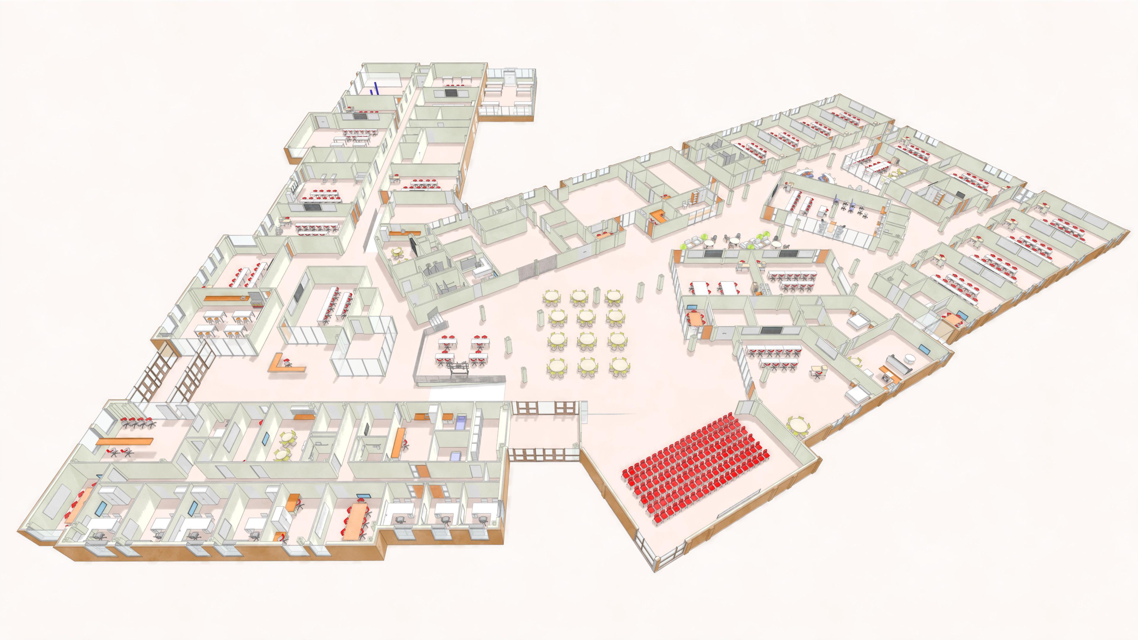
PROGRAM
*Items in red have been updated from the original program through discussions with LCPS or consultants **Items in blue are not currently provided in the SD floor plan
05
SCHEMATIC DRAWINGS
COLOR LEGEND
ADMINISTRATION
SPECIAL EDUCATION
CLASSROOMS
ATHLETICS
LIBRARY
CIRCULATION
COMMON AREAS
RESTROOM AND SERVICE
MAIN ENTRY
PARKING
LOADING
PARKING
BUS ENTRY
LOADING
PARKING
LOADING
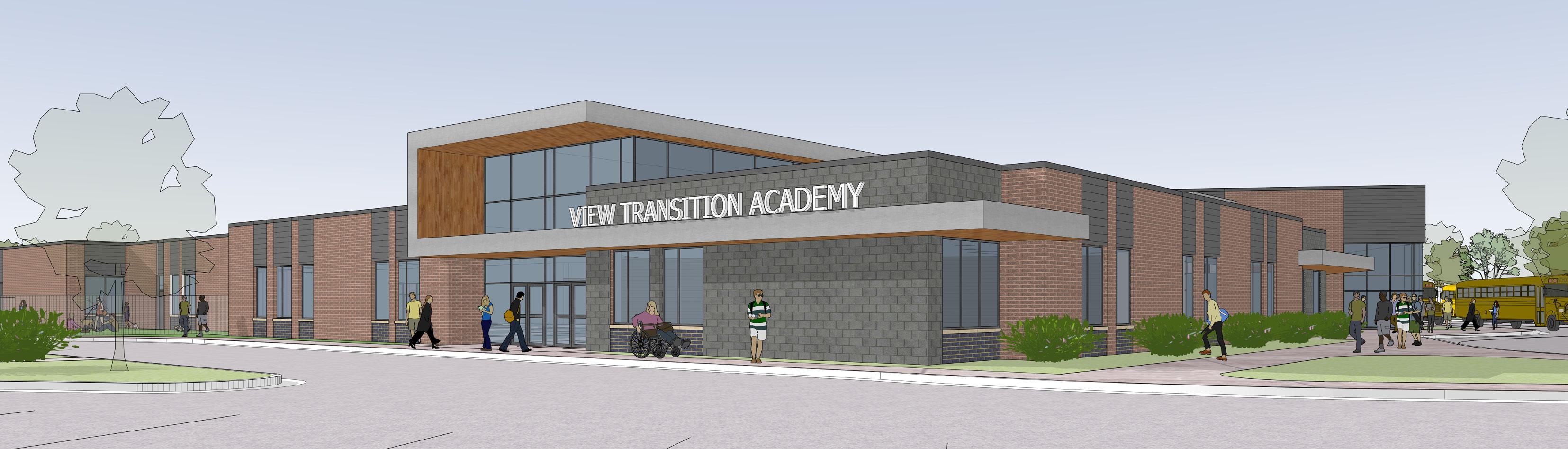
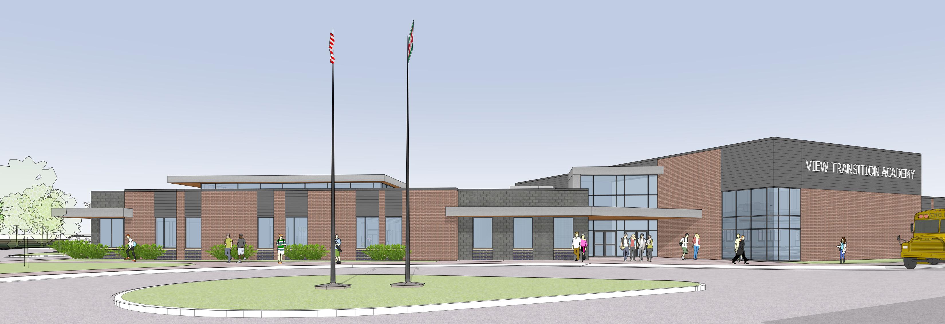
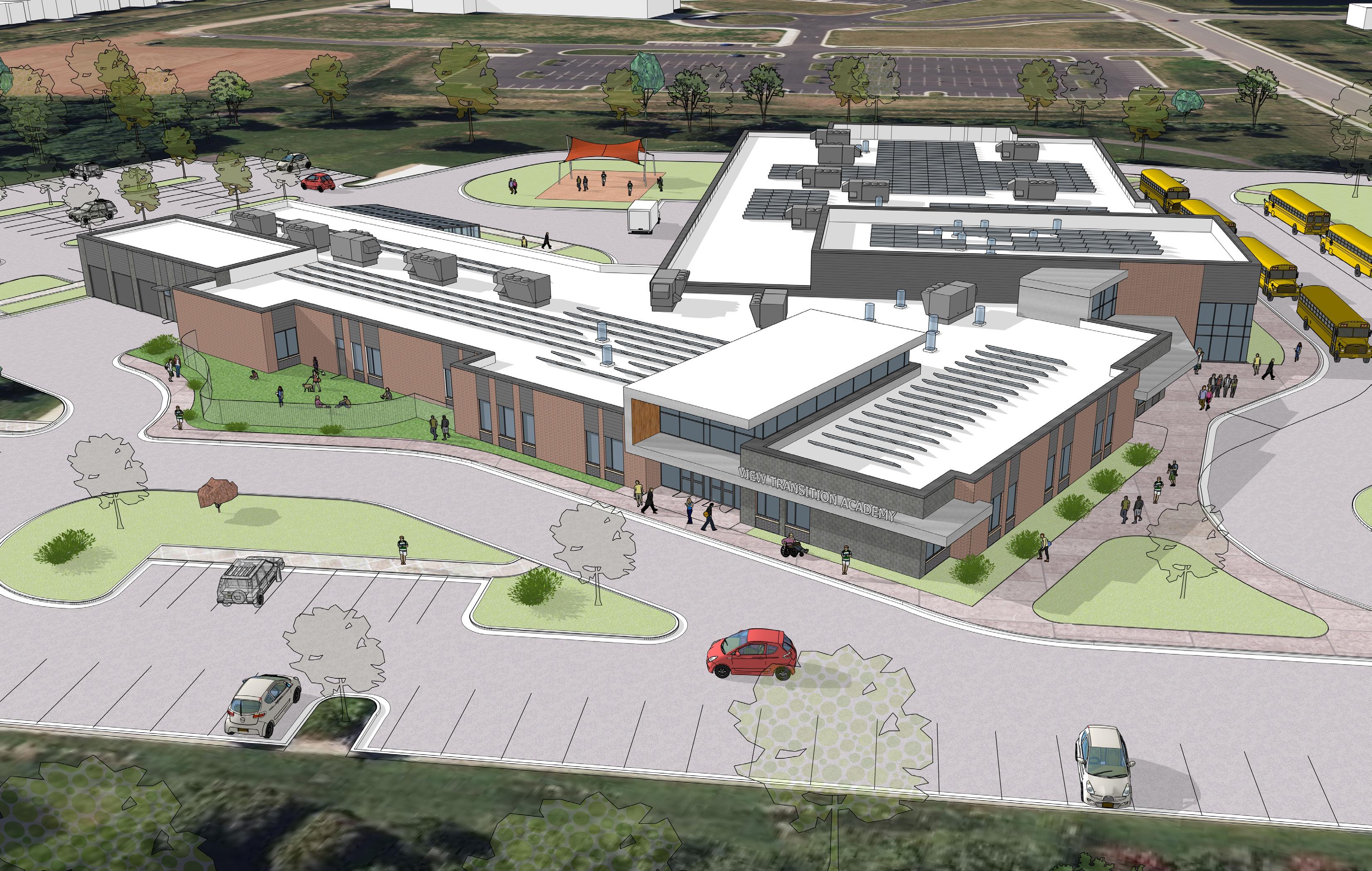
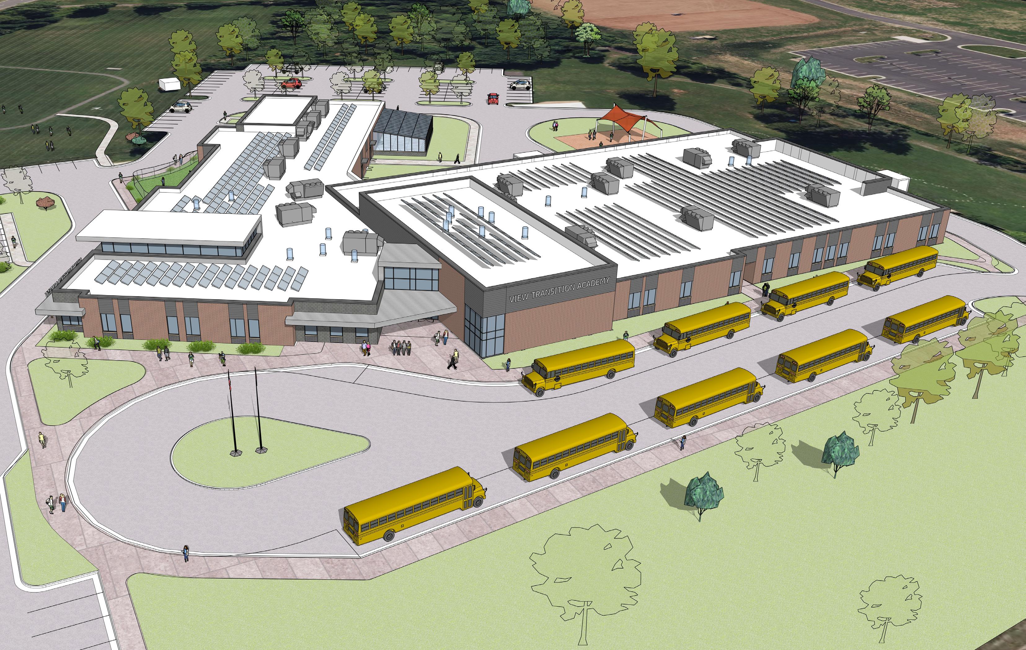
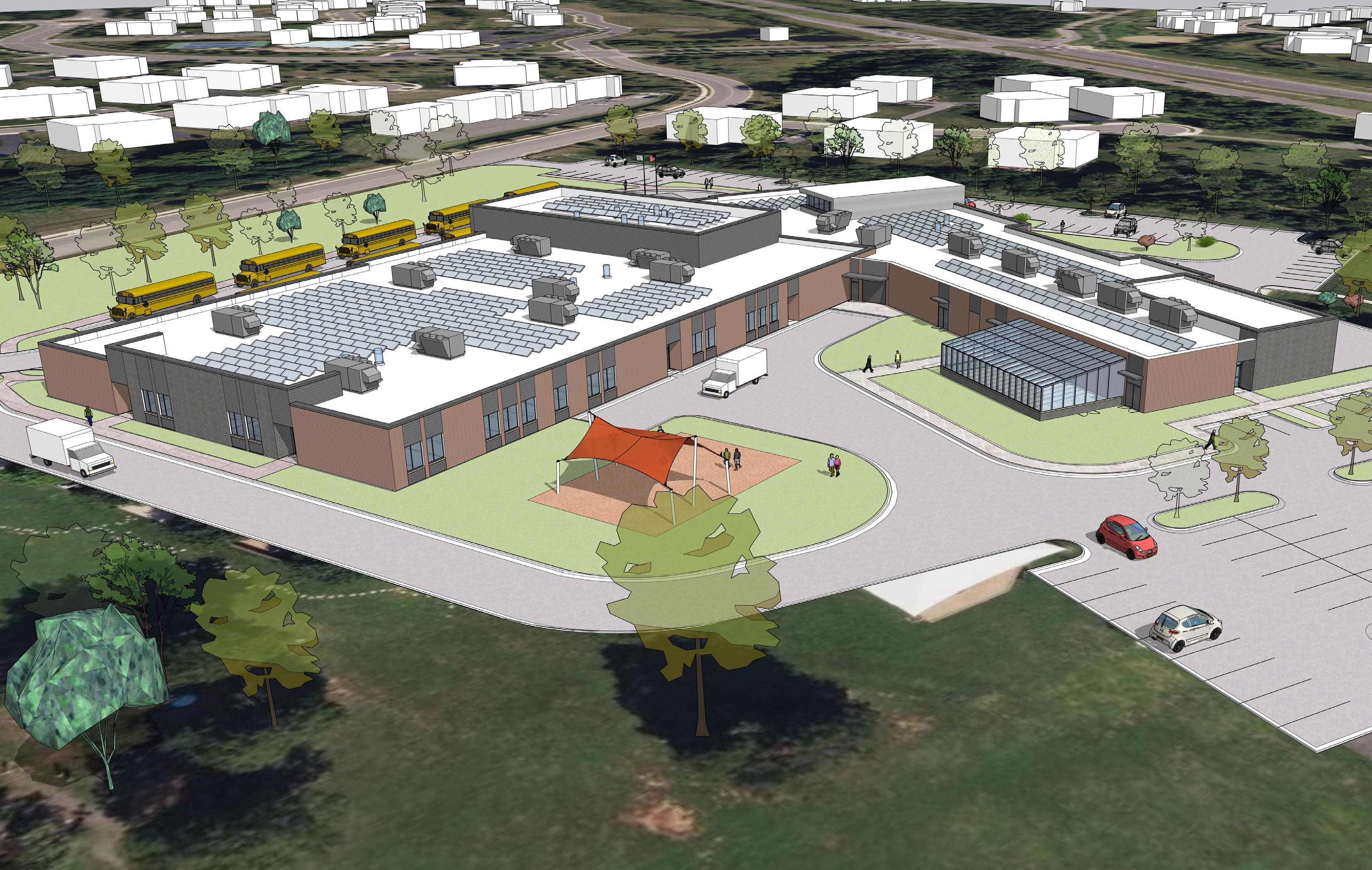
VIEW OF MAIN ENTRY
VIEW OF BUS ENTRY
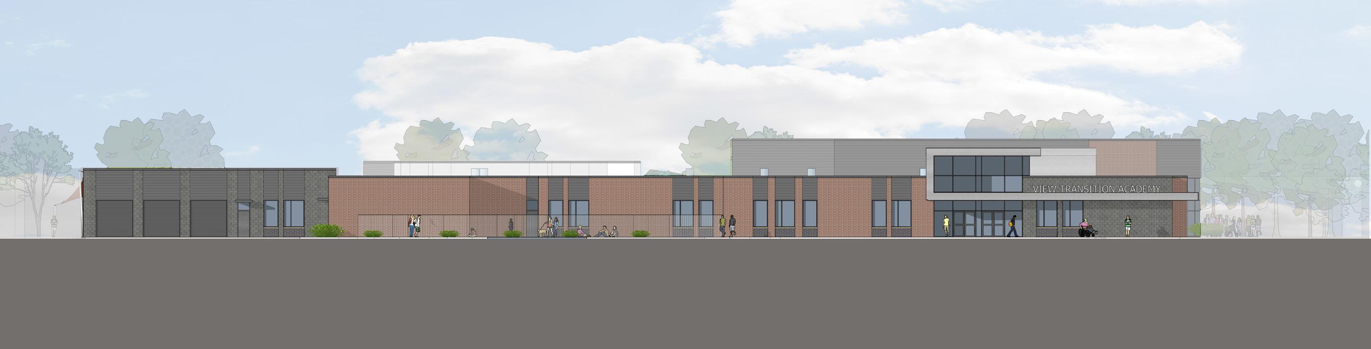
1-MAIN ENTRY ELEVATION
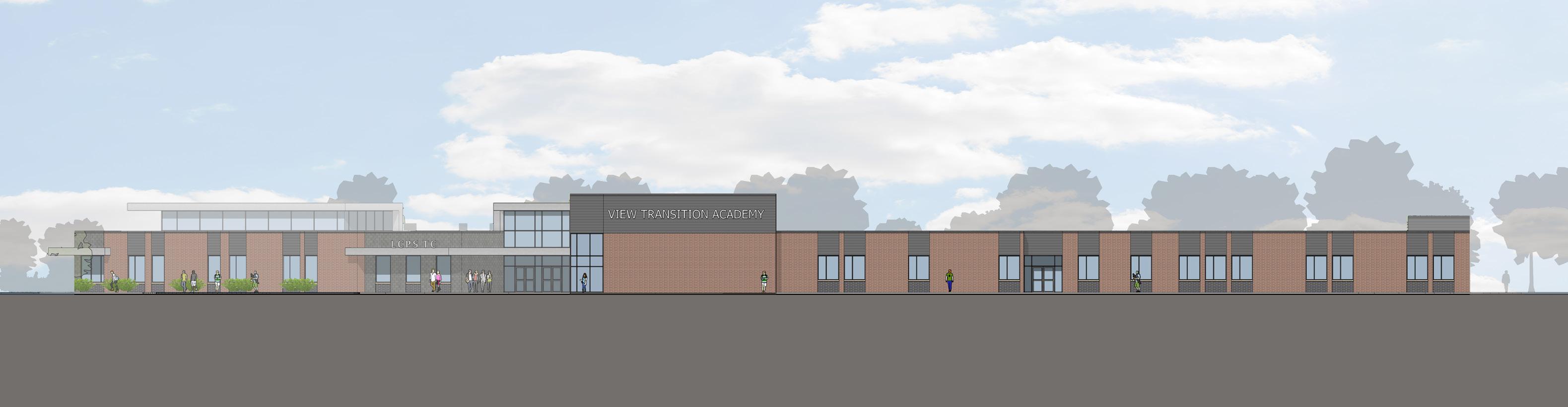
2-BUS ENTRY ELEVATION
LEGEND
BK-1: BROWN/ RED BRICK
BK-2: DARK GRAY BRICK
GF-1: MEDIUM GRAY GROUND FACE CMU MP-1: MEDIUM GRAY SINGLE SKIN METAL PANEL
MP-2: COMPOSITE METAL PANEL AW-1: ALUMINUM WINDOWS W/ INSUL. GLAZING
: ALUMINUM CURTAINWALL ASSEMBLY
BK-1
(TYP.)
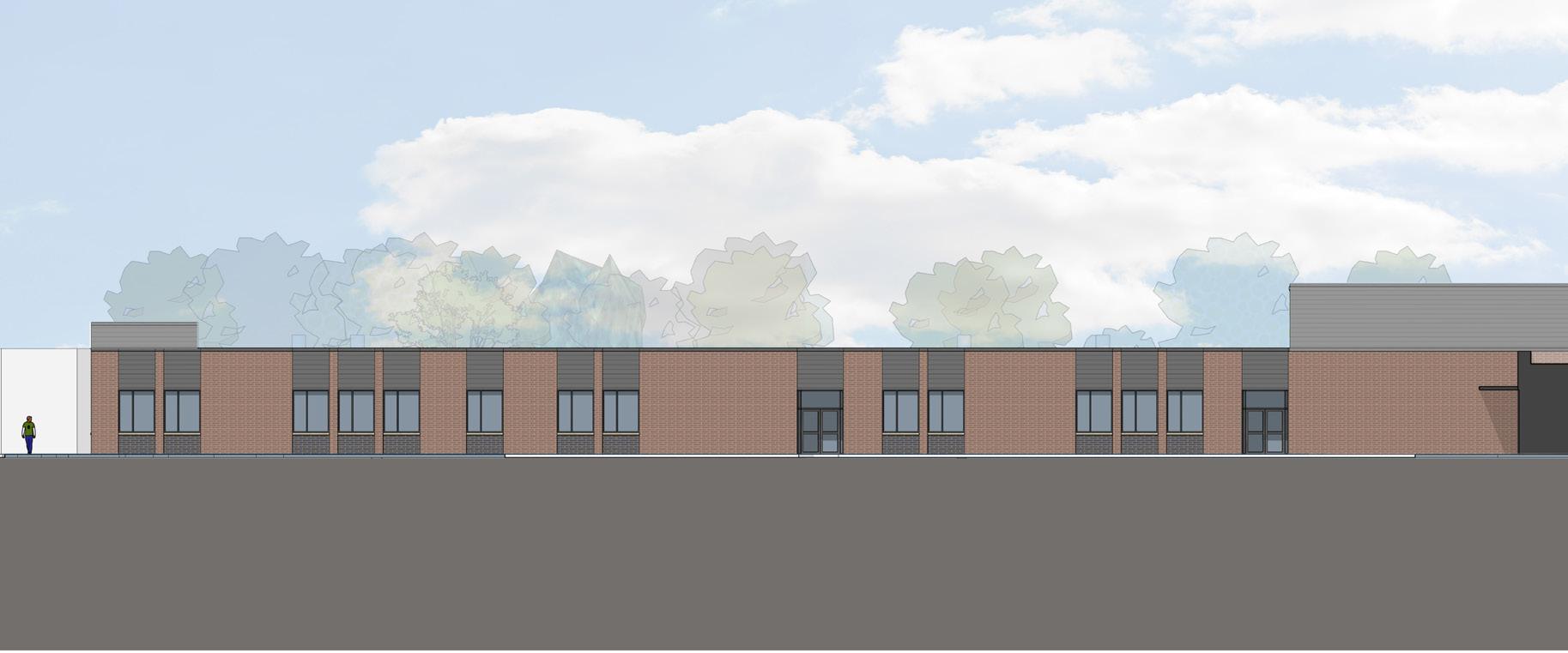
1-CLASSROOM WING BACK ELEVATION
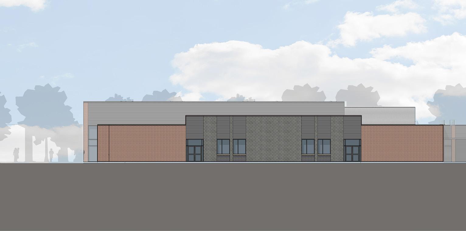
3-SIDE ELEVATION
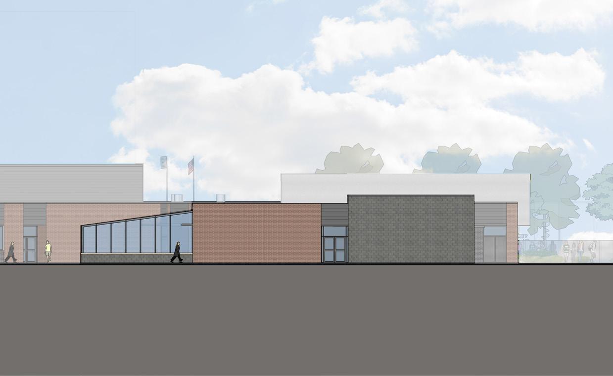
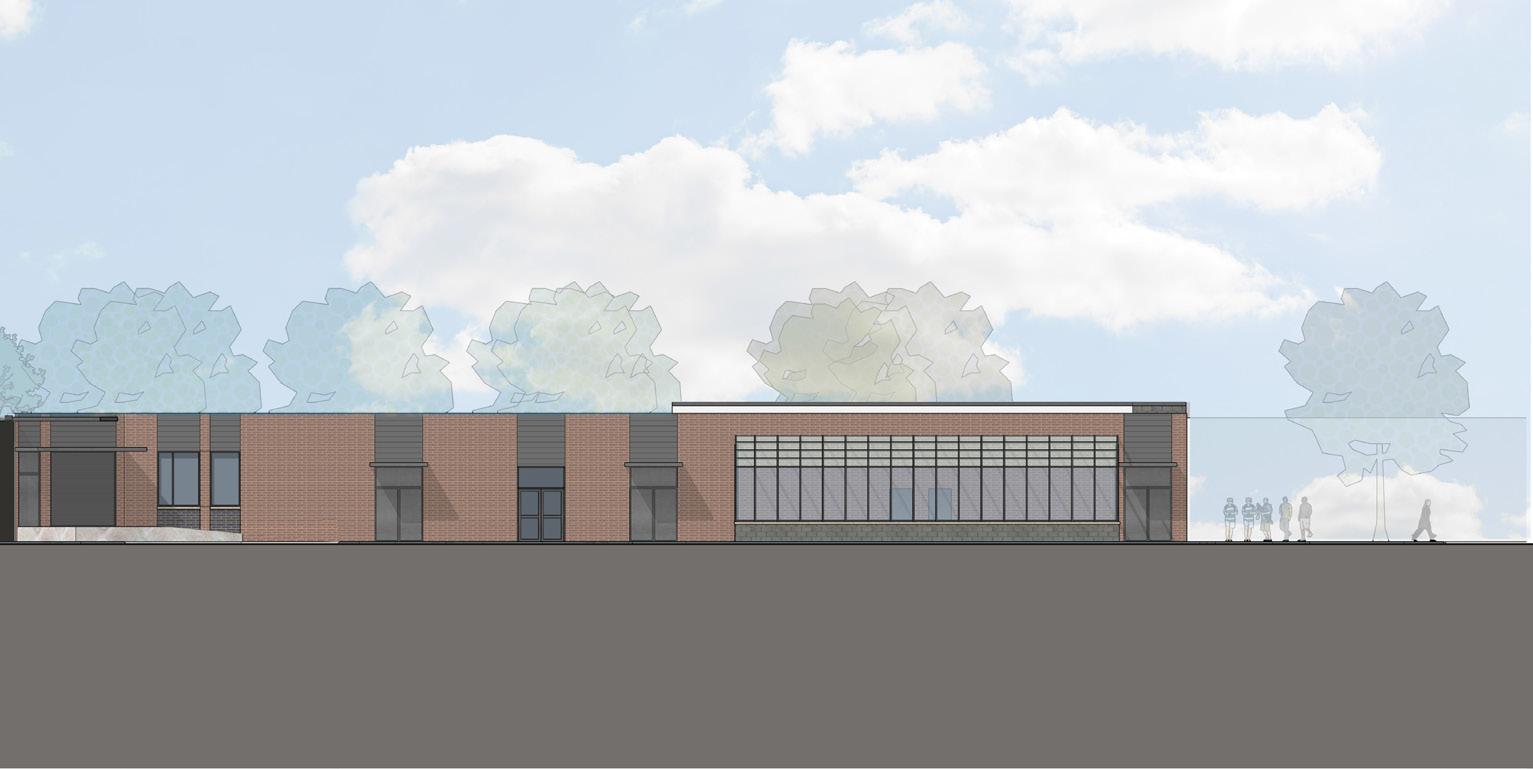
4-LOADING AND
ELEVATION 2-BACK ENTRANCE ELEVATION
: DARK GRAY BRICK
06 SUSTAINABLE DESIGN

LEED v4 for BD+C Schools
LCPS VIEW Transition Academy
January 20, 2026
Integrative Process (v4.1)
LEED for Neighborhood Development
Sensitive Land Protection
High Priority Site
Surrounding Density & Diverse Uses
Access to Quality Transit (v4.1)
Bicycle Facilities (v4.1)
Reduced Parking Footprint (v4.1)
Electric Vehicles (v4.1)
Construction Activity Pollution Prevention
Site Development - Protect or Restore Habitat (v4.1) Open Space
Rainwater Management (v4.1)
Heat Island Reduction
Light Pollution Reduction
Site Master Plan
Joint Use Facilities
Outdoor Water Use Reduction
Indoor Water Use Reduction
Building-Level Water Metering
Outdoor Water Use Reduction
Indoor Water Use Reduction
Cooling Tower Water Use (v4.1) Site Assessment
Minimum Energy Performance Water Metering
Fundamental Commissioning and Verification
Building-Level Energy Metering
Fundamental Refrigerant Management
Enhanced Commissioning
Optimize Energy Performance
Advanced Energy Metering Demand Response (v4.1)
Renewable Energy Production (v4.1) Enhanced Refrigerant Management

Storage and Collection of Recyclables
Construction and Demolition Waste Management Planning
Building Life-Cycle Impact Reduction (v4.1)
Product Disclosure & Optimization - EPDs (v4.1)
Product Disclosure & Optimization - Sourcing of Raw Materials (v4.1)
Product Disclosure & Optimization - Material Ingredients (v4.1)
07
LCPS DESIGN STANDARDS
ACKNOWLEDGEMENT
VLK has reviewed the LCPS standards and requirements FY 22 dated 06/13/2022 and has distributed to all applicable consultants.
SPECIFICATION
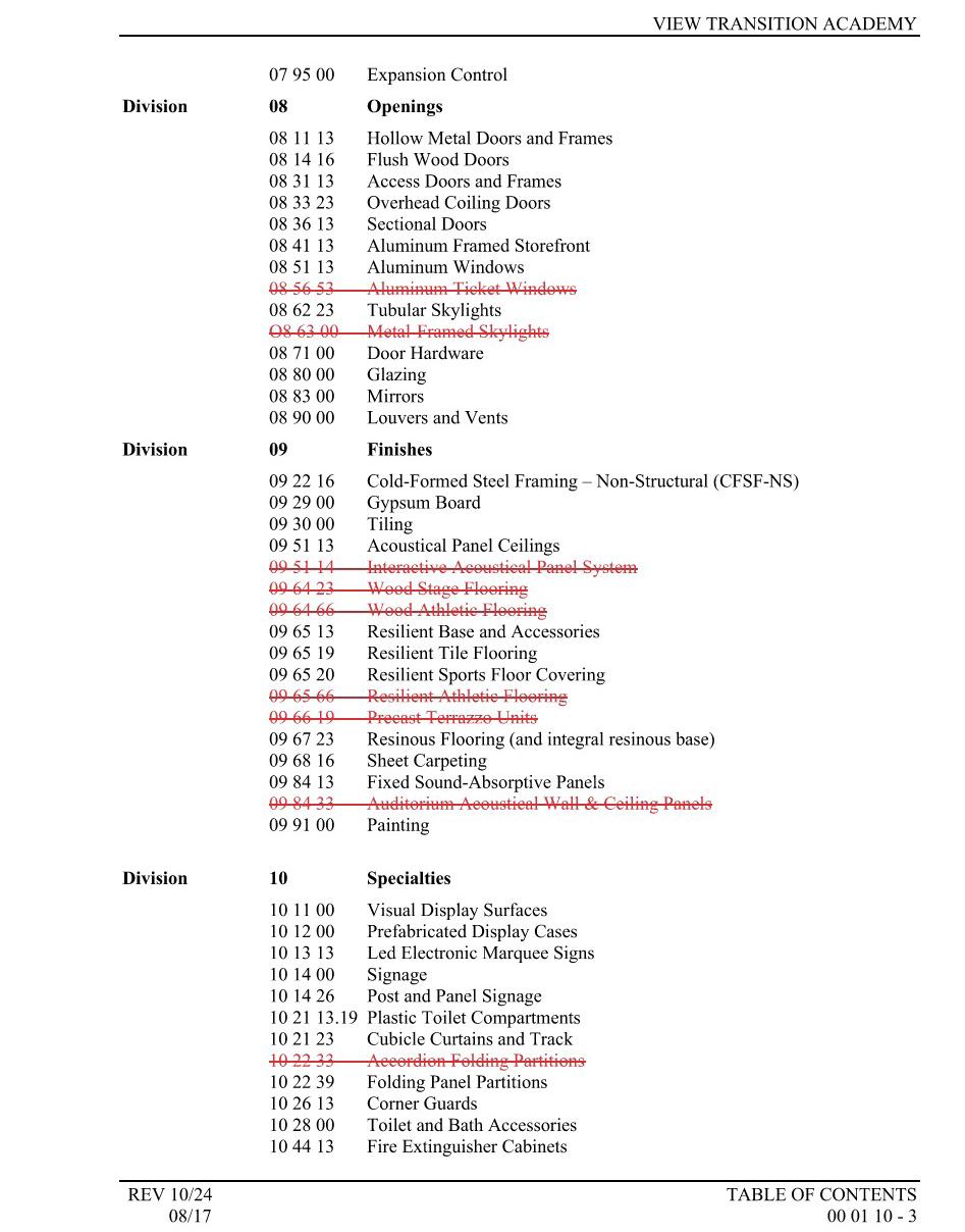
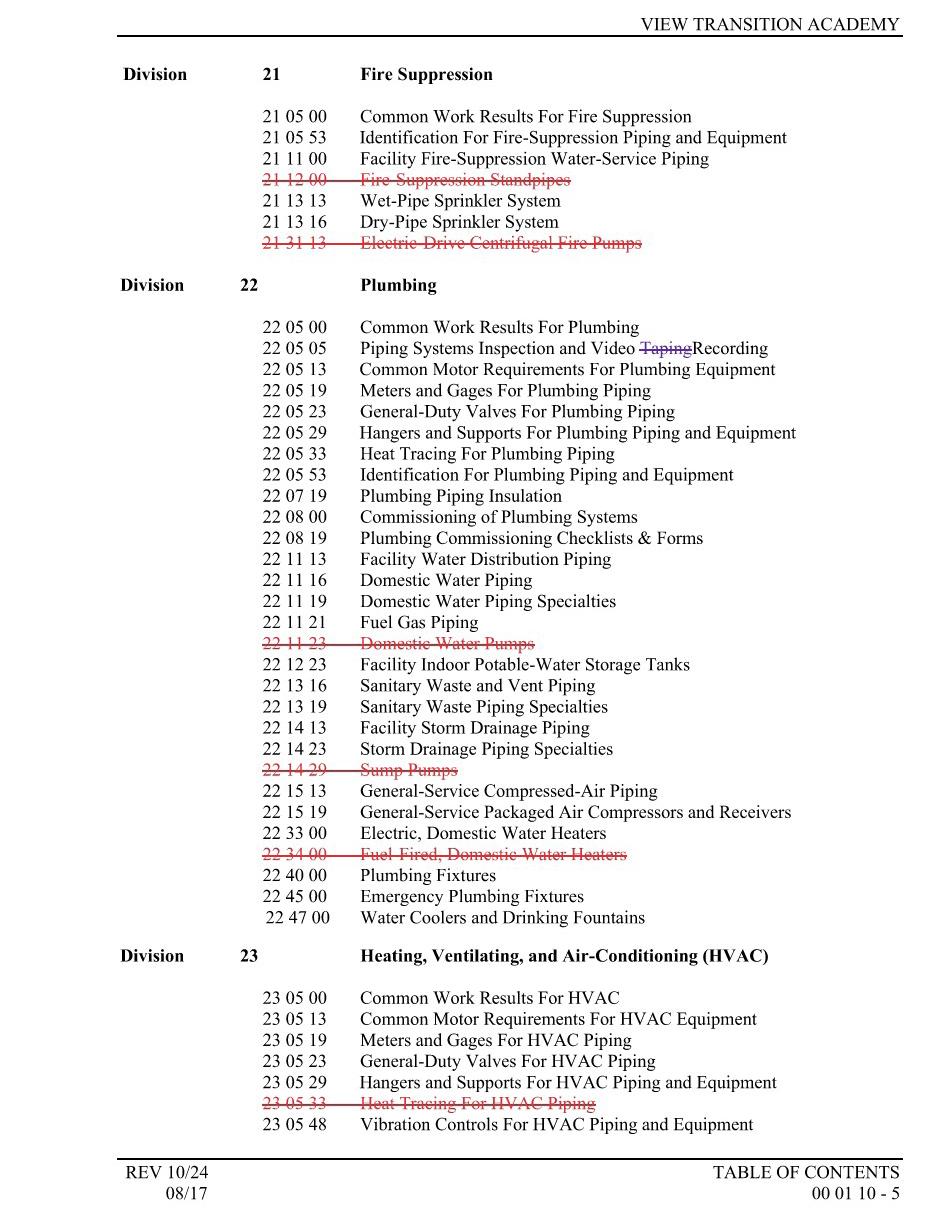
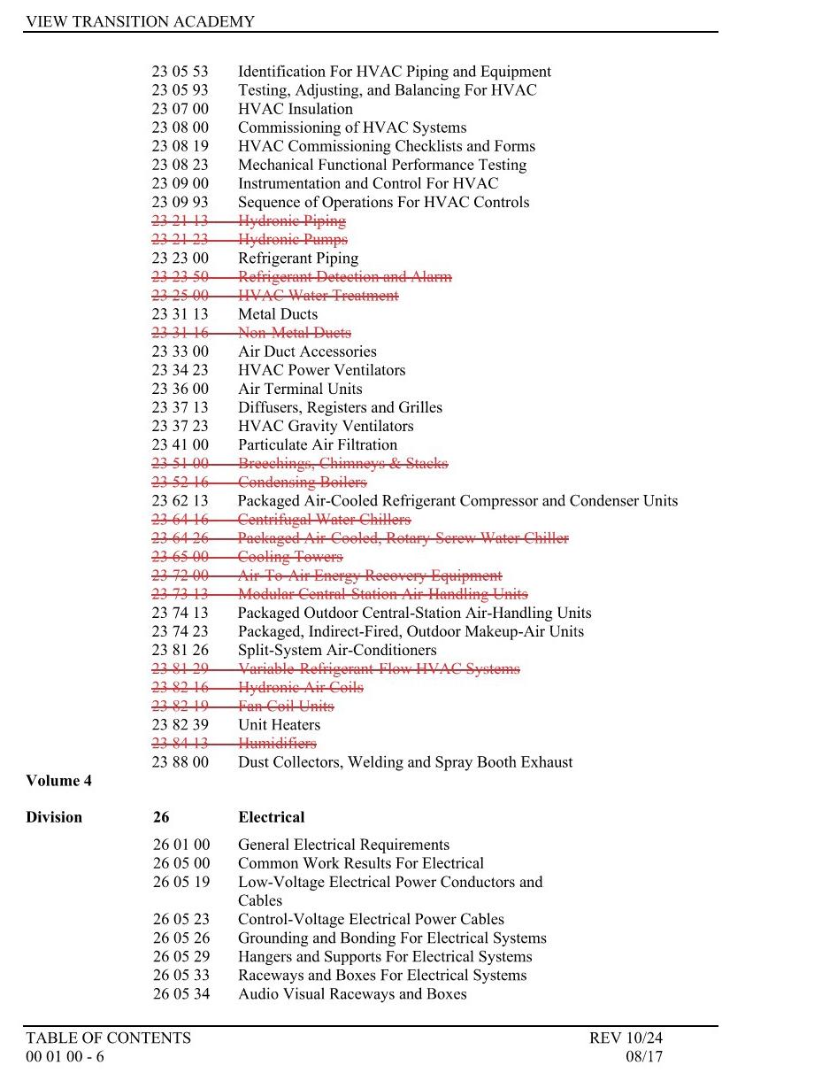
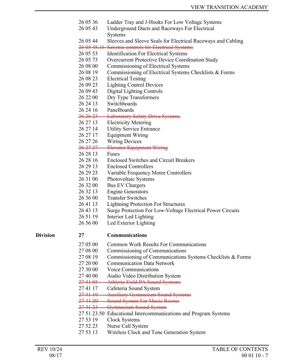
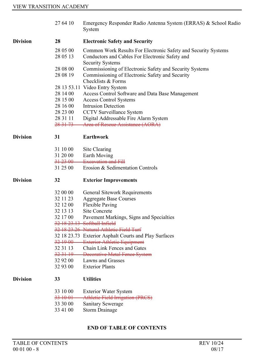
TABLE OF CONTENTS
Volume 1
Division 00 Procurement and Contracting Requirements
Section
00 11 00 Invitation To Bid
00 21 00 Instructions To Bidders (AIA Document A701-1997)
00 31 00 Geotechnical Report Request Form (Subsurface Soil Conditions)
00 41 00 Bid Form
00 52 00 Sample Forms
00 62 00 Standard Agreement between owner and Contractor (AIA Document A101 – 2017)
00 72 00 General Conditions of The Contract For Construction (AIA Document A201- 2007)
00 72 10 Form 9.3.3- Affidavit of Complete Release of Claims
00 72 20 Form 9.4.4- Partial Waiver of Lien (For Each Subcontractor)
00 72 30 Form 9.5.5 -Partial Wavier of Lien (For Contractor)
00 73 13 Owner’s Instructions For Bonds and Insurance
Division 01 General Requirements
01 09 20 LCPS Applicable Standards
01 10 00 Summary (Including Non-Business Hours Construction Work Schedule)
01 14 00 Contractor’s Use of The Premises
01 14 13 Field Engineering
01 21 00 Allowances
01 21 13 Sitework Allowances
01 23 00 Alternates
01 25 01 Pre-Bid Product Substitution Procedures
01 26 00 Contract Modification Procedures
01 29 00 Payment Procedures
01 31 00 Project Management and Coordination
01 32 00 Construction Progress Documentation
01 32 33 Photographic Documentation
01 33 00 Submittal Procedures
01 40 00 Quality Requirements
01 42 00 References
01 50 00 Temporary Facilities and Controls
01 60 00 Product Requirements
01 60 40 Owner Furnished Products
01 74 16 Project Clean Up, Restabilization and Restoration
01 74 19 Construction Waste Management and Disposal
01 75 00 General Commissioning Requirements
01 77 00 Closeout Procedures
01 78 23 Operation and Maintenance Data
01 78 36 Warranties
01 78 39 Project Record Documents
01 78 53 Extra Materials
01 79 00 Demonstration and Training
01 81 13 Sustainable Design Requirements
REV 10/24
OF CONTENTS 08/17


09
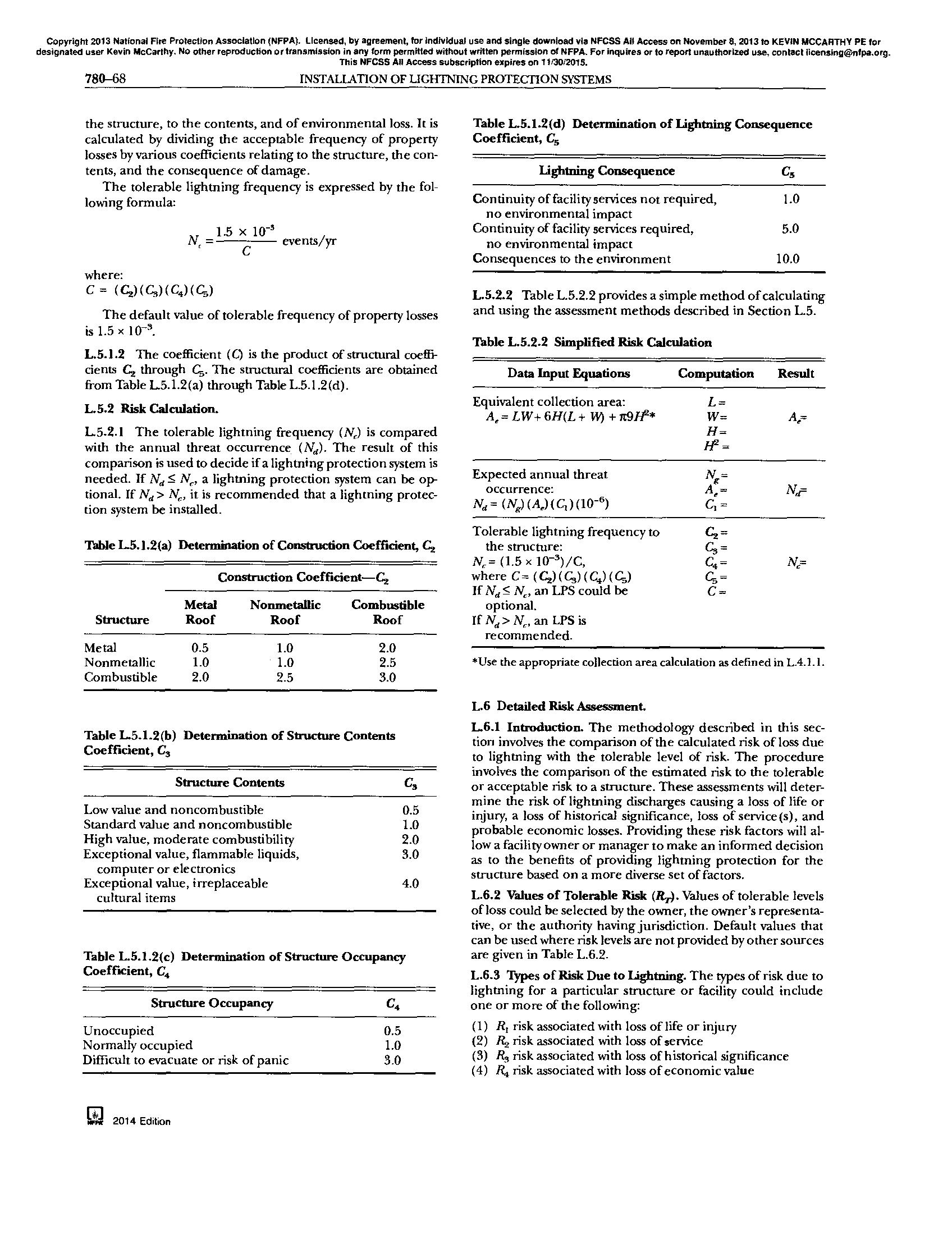
LIGHTNING RISK ASSESSMENT
Project No. : 8232-25
Calculated by: BMM
Checked by:PJM
Date: 01.19.2026
LIGHTNING RISK ASSESSMENT
This calculaton is based on NFPA 780, Annex L (2008)
Structure Length
Structure Width
Structure Height
Equivalent Collective Area
Expected Lightning Strike Frequency
Equivalent Collective Area

Tolerable lightning frequency to the structure
Structural Coefficients C2 = 1
Structure Contents C3 = 1
Structure Occupancy C4 = 1
Lightning Consequence C5 = 5
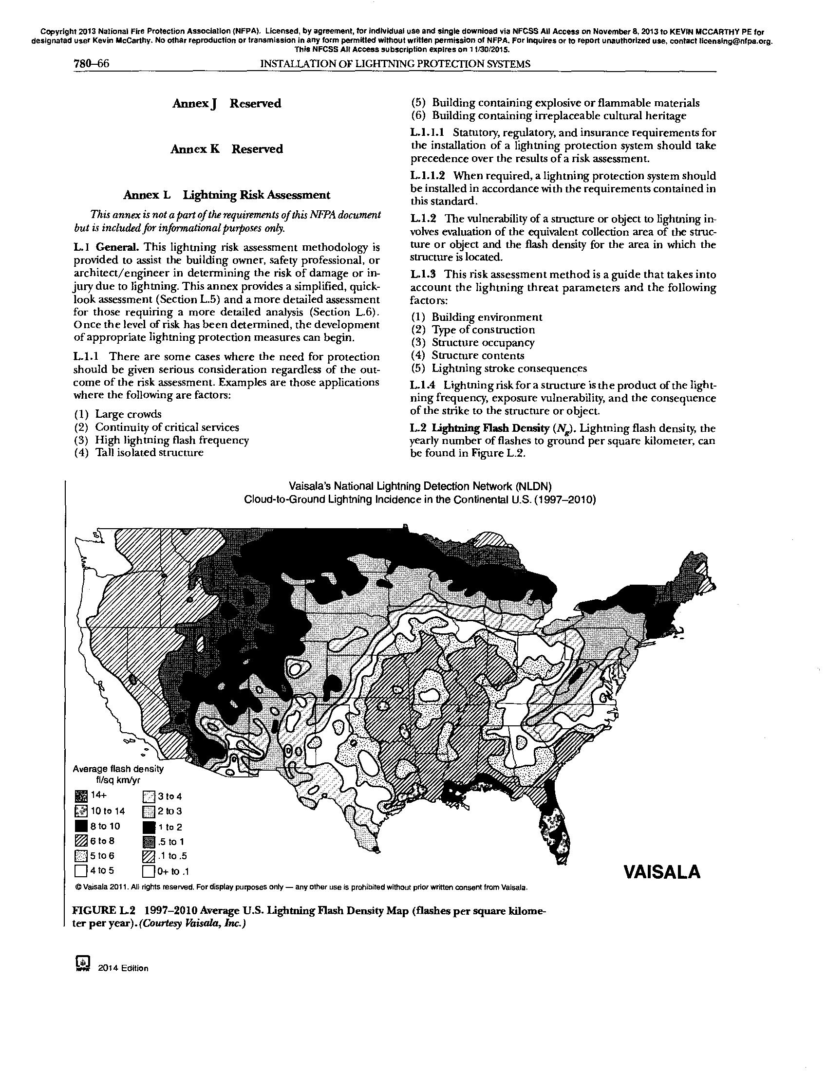
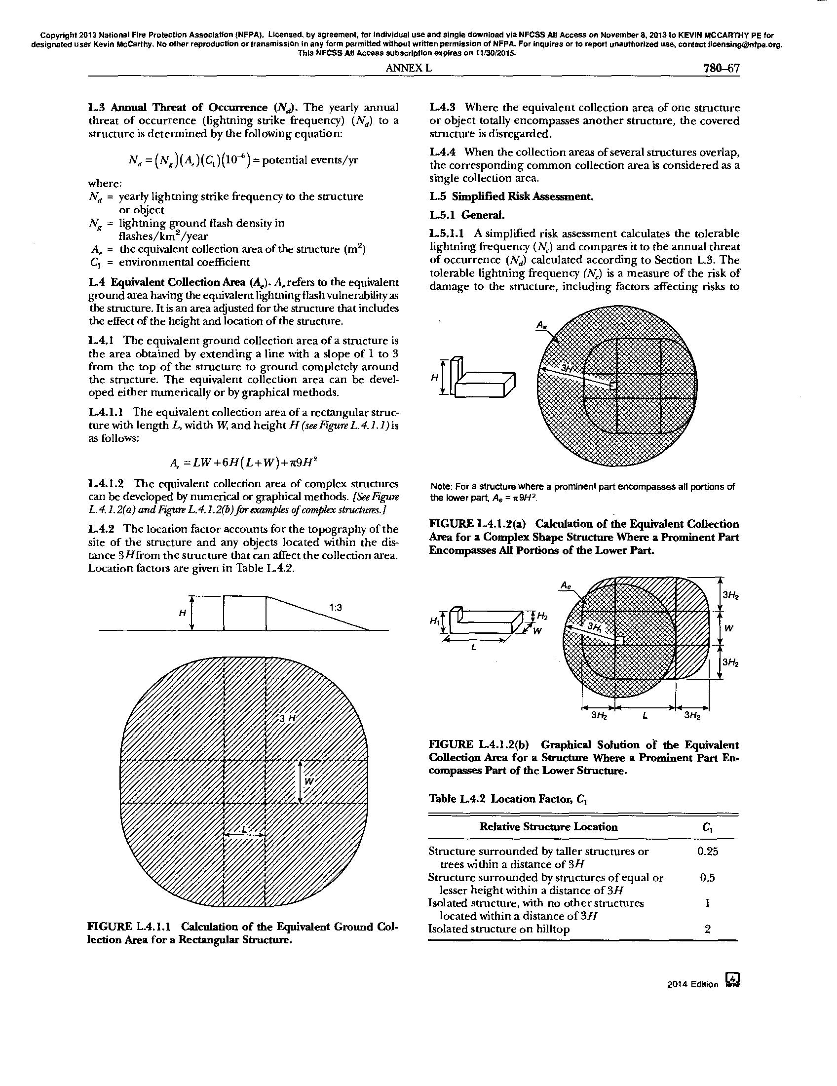
[NFPA 780, Annex L, Figure L.2(a)]
780, Annex L, Figure L.4.1(a)]
780, Annex L, Table L.4.3]
[NFPA 780, Annex L, Table L.5(a)]
[NFPA 780, Annex L, Table L.5(b)]
[NFPA 780, Annex L, Table L.5(c)]
[NFPA 780, Annex L, Table L.5(d)] C =5.00 [C=(C2)(C3)(C4)(C5)]
Result: Lightning Protection System is recommended to be installed (Nd>Nc)
10 LIGHTING CUT SHEET
FEATURES & SPECIFICATIONS
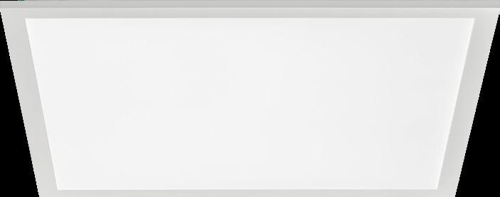
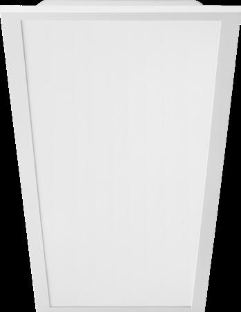
INTENDED USE — The CPX Series LED is a low-glare back-lit panel featuring an external driver. This cost-effective, reliable flat panel is visually comfortable and can be recessed mounted. Suitable for many applications such as schools, offices, retail, convenience stores, hospitals, healthcare facilities and other commercial spaces. A typically configured CPX features a Unified Glare Rating (UGR) starting at 17. Certain airborne contaminants can diminish the integrity of acrylic. Click here for Acrylic Environmental Compatibility table for suitable uses U.S. Patent No. 10,681,784.
CONSTRUCTION — A metal frame with satin white lens provides excellent shielding and uniform luminance. CPX's low-profile design provides increased installation flexibility especially in restricted plenum spaces. The back plate includes integral T-bar clips for installation into T-grid ceilings.
ELECTRICAL — Direct-lit Panel with Long-Life LEDs, coupled with a high-efficiency driver, provide superior illumination for extended service life. Greater than 70% LED lumen maintenance at 60,000 hours (L80>60,000). 0-10V dimming driver. Options available for dimming to 1% or 10%. Contains non-isolated dimming leads.
Integrated Wireless Sensor (single room control) SensorSwitch wireless dimming (SSAIR) or luminaire embedded occupancy sensor control (APIR) with SSAIR pairing for wall switch On/Off /Dimming control or auto off when the space is unoccupied. See page 8 for more details of the integrated wireless sensor. Integrated Sensor (nLight® Wired Networking) This sensor is nLight-enabled, meaning it has the ability to communicate over an nLight network. When wired, using CAT-5 cabling, with other nLight-enabled sensors, power packs, or WallPods, an nLight control zone is created. Once linked to a Gateway, directly or via a Bridge, the zone becomes capable of remote status monitoring and control via SensorView software.
Integrated Smart Sensor (nLight Air Wireless Platform) The RES7 sensor is nLight AIR enabled, meaning it has the ability to communicate over the wireless nLight control platform. It is available with an automatic dimming photocell, and either a digital PIR or a microphonics (PDT) dual technology occupancy sensor. It pairs to other luminaires and wall switches through our mobile app, CLAIRITY+, which allows for simple sensor adjustment.
LISTINGS — CSA certified to meet US and Canadian standards. Damp location listed. IC rated. IP5X Rated. DesignLights Consortium® (DLC) qualified product. Not all versions of this product may be DLC qualified. Please check the DLC Qualified Products List at www.designlights.org/QPL to confirm which versions are qualified. Rated for NSF/ANSI Standard 2 - Light Fixture for Splash Zone and Non-Food Zone. NOM Certified. For use in non-fire-rated installations only.
GOVERNMENT PROCUREMENT — BAA – Product with the BAA option qualifies as a domestic end product under the Buy American Act as implemented in the FAR and DFARS. Product with the BAA option also qualifies as manufactured in the United States under DOT Buy America regulations.
BABA – Build America Buy America: Product with the BAA option also qualifies as produced in the United States under the definitions of the Build America, Buy America Act. Please refer to www.acuitybrands.com/buy-american for additional information.
WARRANTY — 5-year limited warranty. This is the only warranty provided and no other statements in this specification sheet create any warranty of any kind. All other express and implied warranties are disclaimed. Complete warranty terms located at: www.acuitybrands.com/support/warranty/terms-and-conditions
Note: Actual performance may differ as a result of end-user environment and application. All values are design or typical values, measured under laboratory conditions at 25 °C. Specifications subject to change without notice.
CPX LED PANEL

Embed nLight controls today. Prepare for tomorrow.
Tomorrow
User-friendly install Scalability
Enhanced energy savings Space configuration
Code compliance
Capable Luminaire
Future-ready
This item is an A+ capable luminaire, which has been designed and tested to provide consistent color appearance and out-of-the-box control compatibility with simple commissioning when used with Acuity Brands controls products.
All configurations of this luminaire are calibrated and tested to meet the Acuity Brands' specifications for chromatic consistency – including color rendering, color fidelity, and color temperature tolerance around standard CIE chromaticity coordinates.
To learn more about Acuity A+ standards, specifications, and testing visit www.acuitybrands.com/aplus.
Items marked by a shaded background qualify for the Design Select program and ship in 15 days or less. To learn more about Design Select, visit www.acuitybrands.com/designselect
*See ordering tree for details
Configurable CPX LED Flat Panel
battery pack, 10W Linear Constant Power, Certified in CA Title 20 MAEDBS, CA Title 20 MAEDBS, User selectable Self-Diagnostic, AC Activate with Integral Test Switch (LINK ) ‡ E10WRSTAR Emergency battery pack, Enabled with STAR ‡ E7W Emergency Battery Pack, 7W, CA Title 20 Noncompliant ‡ GTD Generator Transfer Device ‡
SSE Sensor Switch Embedded APIR Passive Infrared Occ sensor with auto-dimming photocell APDT Occ sensor dual tech (passive infrared & microphonics) and auto dimming photocell
NLIGHT nLight enabled
NLIGHTER nLight enabled, for use with generator supply EM power
NLIGHTLM nLight enabled with lumen management
NLIGHTERLM nLight enabled with lumen management, for use with generator supply EM power
NLTAIR2 nLight AIR Generation 2 (wireless) enabled ‡
NLTAIREM2 nLight AIR Generation 2 (wireless) enabled and UL924 Emergency Operation, via power interrupt detection. ‡
VAPIR Vertex low-profile on/off occupancy sensor with auto dimming photocell
(blank) No sensor, Control Input function only
PIR Occ sensing with passive infrared - on/off functionality
PDT Occ sensor dual tech (passive infrared & microphonics)
APIR Passive Infrared Occ sensor with auto-dimming photocell
APDT Occ sensor dual tech (passive and microphonics) and auto dimming photocell.
(blank) No sensor, Control Input function only
APIR Passive Infrared Occ sensor with auto-dimming photocell
APDT Occ sensor dual tech (passive and microphonics) and auto dimming photocell
APIREM Occ sensing with passive infrared - on/off functionality and auto dimming photocell and UL924 Emergency operation, via power interrupt detection
APDTEM Occ sensing dual tech- ([passive infrared & microphonics) and auto dimming photocell and UL924 Emergency operation, via power interrupt detection
SSAIR Wireless standalone embedded control by SensorSwitch. ‡ (blank) No sensor, Control Input function only
VAPIR Vertex low-profile on/off occupancy sensor with auto dimming photocell
Fast-blowing fuse ‡
Slow-blowing Fuse ‡ PWS1836 6' pre-wire, 3/8" diameter, 18 gauge, 1 circuit ‡ PWS1846 6' pre-wire, 3/8" diameter, 18 gauge, 2 circuit ‡ PWS1856LV 6' pre-wire, 3/8" diameter, 18 gauge, 1 circuit w/ low voltage ‡ PWS1846 PWSLV Two cables: one 6' pre-wire, 3/8" diameter, 18 gauge, 2 circuits; one 6' pre-wire, 3/8" diameter, 18 gauge ‡ DWAM Anti-Microbial paint
CP Chicago plenum ‡
NPLT Narrow Pallet BAA Buy America(n) Act and/or Build America Buy America Qualified
NOTE: ‡ indicates option chosen has ordering restriction or note. Please reference restrictions/notes chart on next page. Restriction notes are sorted in the sequence they appear in the ordering tree.
Configurable CPX LED Flat Panel
OPTION VALUE RESTRICTIONS/ NOTES
Option value Restriction
Lumen Output High Efficiency (HE) HE is not available with 90CRI.
10000LM Not available with SSAIR or with APIR.
MIN1 Required for all Control Input Options, except SSAIR.
90CRI Not available with any HE lumen package.
‡ Option Value Ordering Notes/ Restrictions
Dimming If Control Input option selected leave this section blank.
EZT Not available with 10000LM combined with 2X4.
347 347 not available with SLD, E10W, E7W, and GTD Options.
SLD Leave Minimum Dimming Level and Dimming option sections blank. Not available with MIN1, MIN10, EZT, ZT or GTD. Not available with any controls.
E10W, E7W Not available with 347. Configurations with E10W or E7W to be used in daisy chaining or through wiring will require a Y connector not supplied. If used with CP option the contractor must verify that the Y connector is Chicago Plenum rated.
E10WRSTAR Not compatible with 347.
GTD Not available with 347, SLD or in 1X4 combined with 6000LM.
NLTAIR2 See UL924 Sequence of Operation Chart below. Can be used as a normal power sensing device for nLight AIR devices and luminaires with EM emergency options .
NLTAIREM2 See UL924 Sequence of Operation Chart below. Leave Sensor option section blank, not available with APIR, APDT, APIREM, or APDTEM.
GLR, GMF Must specify voltage, only available with 120 or 277V.
PWS1836 Not available with E10W, E7W, GTD or E10WRSTAR.
PWS1846 Only available with E10W, E7W or SLD.
PWS1856LV Not available with E10W, E7W or Controls.
PWS1846 PWSLV Not available with Controls or SLD.
CP CP Not available with PWS1836, PWS1846, PWS1856LV, or PWS1846 PWSLV, NLIGHT, NLIGHTER, NLIGHTLM, NLIGHTERLM options.
ACCESSORIES
Accessories: Order as separate catalog number.
ILBLP CP10 HE SD A IOTA 10 Watt Constant Power, High Efficiency LED Emergency Driver for CA Title 20 ‡
ELA PSDMT Remote mount tray for ILBLP battery.
DGA14 Drywall grid adapter for 1x4 recessed fixture.
DGA22 Drywall grid adapter for 2x2 recessed fixture.
DGA24 Drywall grid adapter for 2x4 recessed fixture.
1X4SMKSH Multi-Use Surface Mount Kit 1x4, Shallow Depth
2X2SMKSH Multi-Use Surface Mount Kit 2x2, Shallow Depth
2X4SMKSH Multi-Use Surface Mount Kit 2x4, Shallow Depth
1X4SMKSHP PAF Multi-Use Surface Mount Kit 1X4 Post-Paint
2X2SMKSHP PAF Multi-Use Surface Mount Kit 2X2 Post-Paint
2X4SMKSHP PAF Multi-Use Surface Mount Kit 2X4 Post-Paint
PAC 2DNF 36 Panel Air Craft Kit, 2 cables with Y splitter, No Power Feed, 36 inches. Recommended for 2X2 or 1X4 Panel Fixture.
PAC 2DF 36 Panel Air Craft Kit, 2 cables with Y splitter, with Power Feed, 36 inches. Recommended for 2X2 or 1X4 Panel Fixture. 1
PAC 4DNF 36 Panel Air Craft Kit, 4 cables, No Power Feed, 36 inches. Recommended for 2X4 or 2X2 or 1X4 Panel Fixtures.
PAC 4DF 36 Panel Air Craft Kit, 4 cables, with Power Feed, 36 inches. Recommended for 2X4 or 2X2 or 1X4 Panel Fixtures. 1
PAC 2DNF 72 Panel Air Craft Kit, 2 cables with Y splitter, No Power Feed 72 inches. Recommended for 2X2 or 1X4 Panel Fixture.
PAC 2DF 72 Panel Air Craft Kit, 2 cables with Y splitter, with Power Feed, 72 inches. Recommended for 2X2 or 1X4 Panel Fixture. 1
PAC 4DNF 72 Panel Air Craft Kit, 4 cables, No Power Feed, 72 inches. Recommended for 2X4 or 2X2 or 1X4 Panel Fixtures.
PAC 4DF 72 Panel Air Craft Kit, 4 cables, with Power Feed, 72 inches. Recommended for 2X4 or 2X2 or 1X4 Panel Fixtures. 1
RK8BDP 2P U Disconnect Plug (BDP), 2 Pole, Package of 1
RK8BDP 3P U Disconnect Plug (BDP), 3 Pole, Package of 1
RK8BDP 2P J10 Disconnect Plug (BDP), 2 Pole, Package of 10
RK8BDP 2P J40 Disconnect Plug (BDP), 2 Pole, Package of 40
CPX Gasket Kit Fixture/Grid foam gasket, cut to size, 2x4/1x4/2x2 2
Emergency Battery Delivered Lumens
Use the formula below to determine the delivered lumens in emergency mode
Delivered Lumens = 1.25 x P x LPW
P = Output power of emergency driver (10W for PS1055) LPW = Lumen per watt rating of the luminaire.
Notes
1 For MVOLT only, not available with 347V.
2 CPX Gasket kit accommodates a single 1x4, 2x2 or 2x4 CPX fixture. This kit does not make the fixture IP65 compliant.
UL924 Sequence of Operation
The below information applies to all nLight AIR devices with an EM option.
EM devices will remain at their high-end trim and ignore wireless lighting control commands, unless a normal-power-sensed (NPS) broadcast is received at least every 8 seconds.
• Using the CL AIR ITY+ mobile app, EM devices must be associated with a group that includes a normal power sensing device to receive NPS broadcasts.
• Only non-emergency rPP20, rLSXR, rSBOR, rSDGR, and nLight AIR luminaires with version 3.4 or later firmware can provide normal power sensing for EM devices. See specification sheets for control devices and luminaires for more information on options that support normal power sensing.
Configurable CPX LED Flat Panel
Emergency Battery Pack Options - Field Installable
All the above are UL Listed products that are certified for field install external/remote to the fixture.
*Minimum delivered lumen output to assist in product selection for increased fixture mounting height. The CP10 delivered emergency illumination outperforms legacy 1400 lumen fluorescent emergency ballast. Please contact us at techsupport@iotaengineering.com for any Emergency Battery related questions.
Enabled with STAR
Emergency Lighting with Self-Testing Automated Reporting (STAR), enables self-testing and automated reporting to aid in life safety code compliance. Build your solution and choose your preferred deployment from Mobile STAR, where test data is logged in each individual unit and broadcast to the ClAIRity™+ app, or Connected STAR, where test data is logged in the STAR Gateway by IOTA® and emailed directly. Leave the ladders, disruptions and written records behind with emergency lighting solutions with STAR!
Life Safety Code NFPA 101 testing and reporting requirements for emergency lighting include:


Testing for 30 seconds every 30 days
Testing for 90 minutes once a year
Record keeping and to report to the authority having local jurisdiction
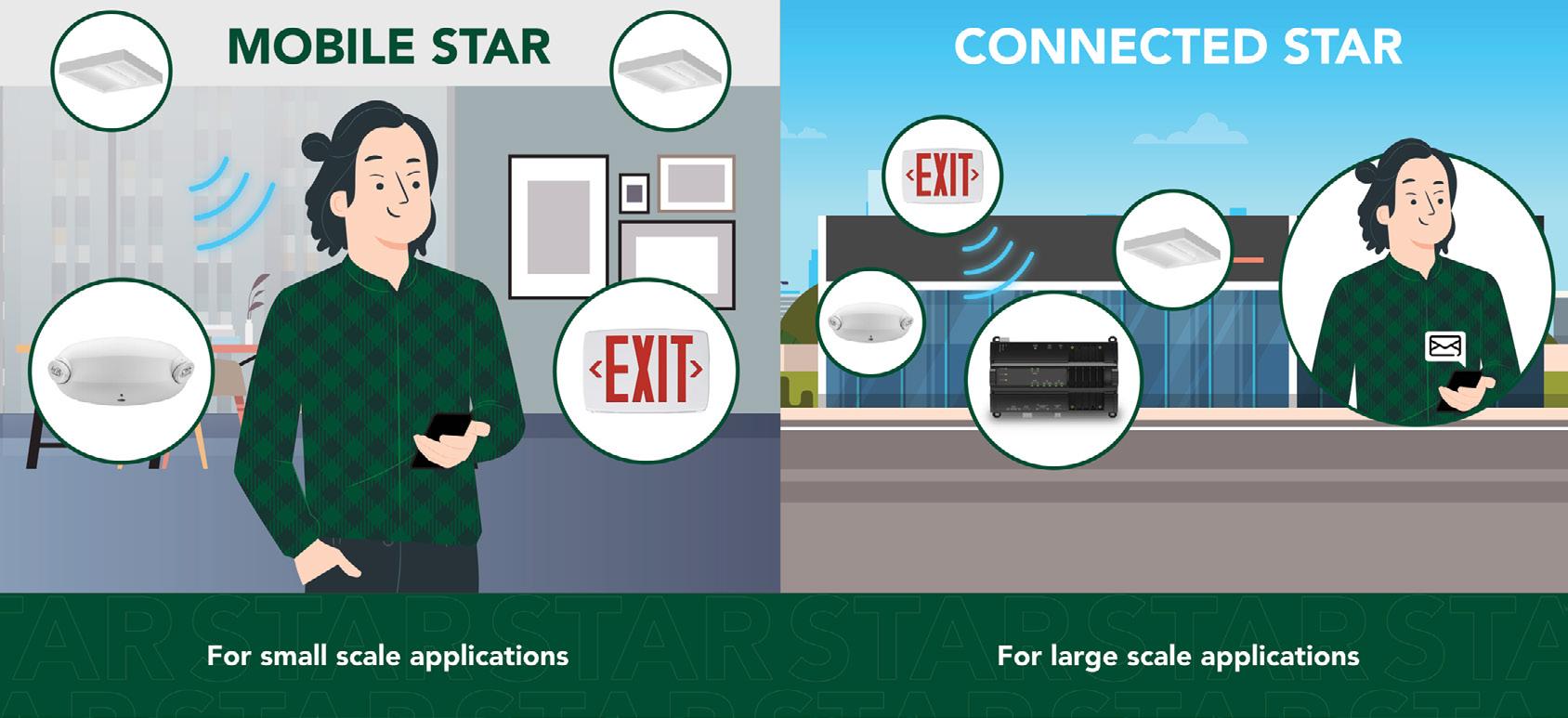
Configurable CPX LED Flat Panel
PERFORMANCE DATA
Configurable CPX LED Flat Panel
Optical Performance
Lumen Package A12
*UGR varies based on luminaire options and is affected by application dependent parameters. Numbers depicted here are considered “Luminaire-UGR and/or “PointUGR” values. To determine a more precise maximum UGR value (“Application-UGR”), a full lighting design layout should be completed with the selected luminaire configuration for each application.
Lumen Maintenance
Reported Lumen Maintenance Forecasted Lumen Maintenance L90 @ 37k Hrs / L80 @ >60k Hrs / L70 @ > 60k Hrs L90 @ 37k Hrs / L80 @ 76k Hrs / L70 @ 120k Hrs
*Note - Reported LM based on IES standard 6X test period for LM-80 report. Forecasted LM based on TM-21 report extrapolation past 6X LM-80 testing.
CPX compatible with Sensor Switch™ WSX-D and SPOD wall switches.
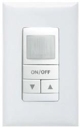
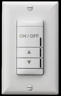
PHOTOMETRICS
See www.lithonia.com for photometry reports.
WSX-D SPOD
Configurable CPX LED Flat Panel
Intelligent Luminaire Technology Guide
NLIGHTLM + PIR
NLIGHTLM + APIR = nIO EZ PH N80 + nES 7 ADCX
enabled with 80% contstant lumen management with PIR integral occupancy sensor with automatic dimming photocell.
NLIGHTLM + APDT = nIO EZ PH N80 + nES PDT 7 ADCX nLight enabled with 80% contstant lumen managmentwith dual technology occupancy controls sensor with automatic dimming photocell.
NLIGHTERLM + (blank) = nIO EZ PH ER N80 Emergency nLight enabled only with 80% contstant lumen managment. No onboard sensor.
NLIGHTERLM + PIR = nIO EZ PH ER N80 + nES 7 Emergency nLight enabled with 80% contstant lumen managment with PIR integral occupancy sensor.
NLIGHTERLM + PDT nIO EZ PH ER N80 + nES PDT 7 Emergency nLight enabled with 80% contstant lumen management with dual technology occupancy control sensor.
NLIGHTERLM + APIR nIO EZ PH ER N80 + nES 7 ADCX Emergency nLight enabled with 80% contstant lumen management with PIR integral occupancy sensor with automatic dimming photocell.
NLIGHTERLM + APDT = nIO EZ PH ER N80 + nES PDT 7 ADCX Emergency nLight enabled with 80% contstant lumen management with dual technology occupancy controls sensor with automatic dimming photocell.
NLTAIR2 + (blank) = RIO EZ PH 180D G2 nLight AIR Generation 2 enabled.
NLTAIREM2 + (blank) = RIO EZ PH ER 180D G2 nLight AIR Generation 2 enabled
NLTAIR2 + APIR RES7 G2 nLight AIR Generation 2 enabled.
NLTAIR2 + APDT RES7 PDT 90D G2 nLight AIR Generation 2 enabled.
NLTAIR2 + APIREM = RES7 EM 90D G2 nLight AIR Generation 2 enabled.
NLTAIR2 + APDTEM = RES7 PDT EM 90D G2 nLight AIR Generation 2 enabled.
Configurable CPX LED Flat Panel
Single Lighting Controls Platform for Indoor & Oudoor Spaces
nLIGHT® is your networked lighting controls platform, for indoor and outdoor applications, providing wired or wireless options. Scaling from room to campus-wide applications, it is the one platform that grows with your business today and tomorrow; to seamlessly address energy cost optimization, building code compliance, improved occupant comfort, and much more. nLIGHT also interfaces with DALI®, BACnet®, DMX and additional third-party devices. nLIGHTcontrols.com

1. Install the luminaires with embedded controls
2. Install the nLight Wired wall switch
3. Connect the luminaires using standard CAT-5e cables and the controls devices will automatically discover each other and work (plug and play).
nLight embedded fixtures offer:
Manual Dimming
Motion Sensing and/or Daylight Harvesting
Fixture or Group Level Control
Flexibility
Wireless Wall Switch (nLight AIR Only)
Astronomical and Time of Day Scheduling
Scalable Solution
Future-Ready
1. Install the luminaires with embedded controls

2. Install the nLight AIR batterypowered wall switch
3. Use CLAIRITY + mobile app to pair the fixture with the wall switch and is desired, customize the sensor settings
Customers get:
Convenience and visual comfort for occupants
Energy savings and code compliance
Ability to configure lighting to the space requirements
Ease of fixture moves, adds and changes
Ease and flexibility of placement
Energy savings and building security
nLight controls to grow with your business
nLight platform to set foundation for future upgrades and capabilities
Configurable CPX LED Flat Panel
Performance You Can Count On
SensorSwitch™ offers standalone wired and wireless lighting controls solutions designed for room-based applications. Our products offer reliable performance and ease of installation.
Sensorswitch.com
Wired Embedded Controls
1. Install the luminaires with embedde controls
2. Install and wire the wall switch to power
3. Connect load and 0-10 dimming wires from the wall switch to the luminaires.
SensorSwitch WSXA D
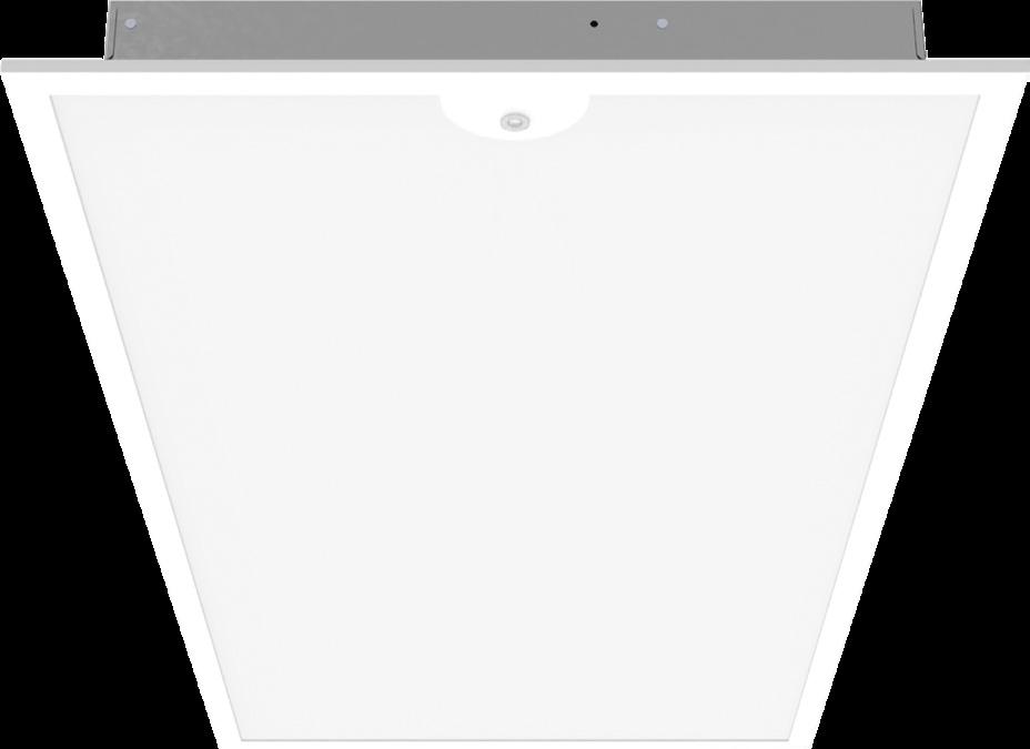
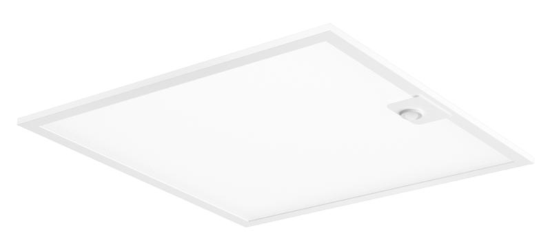
Wireless Embedded Controls
1. Install the luminaires with embedde controls
2. Insert the pairing tool into the pinhole on the wall switch; press and hold any button for 6 seconds.
3. Once paired, each fixture will individually dim down to 10% brightness. All products will be fully functional.
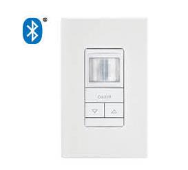
SensorSwitch WSXA SSA
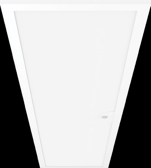
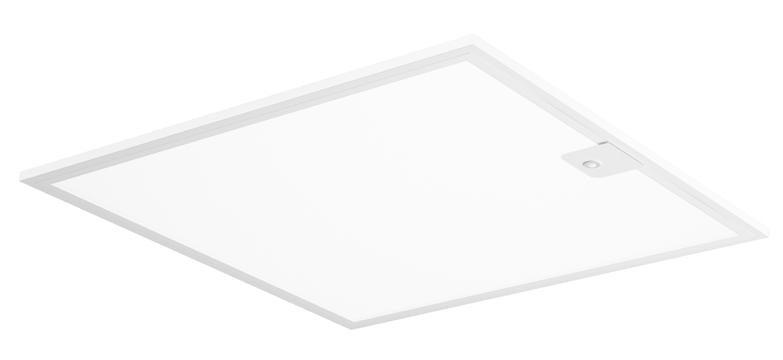
CPX 2X4 with SSAIR APIR Sensor
CPX 1X4 with SSAIR APIR Sensor
CPX 2X2 with SSAIR APIR Sensor
CPX 2X2 RES7
Configurable CPX LED Flat Panel
DIMENSIONS
Length: 47.8" (121.4cm)
Width: 23.8" 60.5cm
Depth: 2.3" 5.7cm
All dimensions are the same except the height with the STAR configuration. Includes conduit
1X4- 3.21"-depth
2X2- 3.24"-depth
2X4-3.25"-depth
FEATURES & SPECIFICATIONS
INTENDED USE — Typical applications include corridors, lobbies, conference rooms and private offices.
CONSTRUCTION — Retrofit, remodel, and new construction mounting types. See table for compatible ceiling openings and thickness range.
Optional goof rings available for additional overlap trim coverage. 1/2"-1-1/2" ceiling thickness
25° ambient temperature
IC rated up to 1000lm
OPTICS — LEDs are binned to a 3-step Mac Adam Ellipse. 55° cutoff
New construction frame accessories approved for 8 (4 in/4 out) No. 12 AWG conductors rated for 90°C through wiring.
80CRI standard (90CRI optional)
UGR — UGR is zero for fixtures aimed at nadir with a cut-off equal to or less than 60deg, per CIE 117-1996
Discomfort Glare in Interior Lighting. UGR FAQ
ELECTRICAL — Adjustable lumen output with four module options. Fixed lumen options also available.
MVOLT 120/277V 50/60Hz driver (0-10V & 120V Phase Dimming to 10% or 1% min dimming level)
FCC CFR Title 47 Part 15 Class A for 277V. FCC CFR Title 47 Part 15 Class B for 120V
LUMEN MAINTENANCE — L80 at 60,000 hours
LISTINGS — Certified to US and Canadian safety standards. Damp location standard (Wet Location (WL) optional, requires covered ceiling). TAA compliant. UFC (3-530-01) specification compliant for power factor and THD. GSA P100 6.2.4 compliant for power quality at full output; compliant up to 2000lm at fully dimmed output. Drivers are ROHS compliant Title 24 compliant (90CRI, up to 1000lm).
WARRANTY — 5-year limited warranty. This is the only warranty provided and no other statements in this specification sheet create any warranty of any kind. All other express and implied warranties are disclaimed. Complete warranty terms located at: www.acuitybrands.com/support/warranty/ terms-and-conditions
Note: Actual performance may differ as a result of end-user environment and application. All values are design or typical values, measured under laboratory conditions at 25 °C. Specifications subject to change without notice.
Performance Data
Lumen Output Wattage
• Tested in accordance with IESNA LM-79-08. u8226
• Tested to current IES and NEMA standards under stabilized laboratory conditions.
• CRI: 80 typical
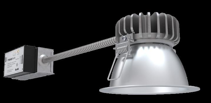
LBR4
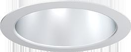
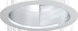
Items marked by a shaded background qualify for the Design Select program and ship in 15 days or less. To learn more about Design Select, visit www.acuitybrands.com/designselect. *See ordering tree for details
Retrofit | Remodel
Open Trim
Wallwash Trim
Design Select options indicated by this color background.
remote test switch
ETS Iota Emergency Transfer System
E10WCP Battery pack (10W constant power) T20 Compliant integral test switch
E10WCPR Battery pack (10W constant power) T20 Compliant remote test switch
E10WRSTAR Emergency battery pack, 10W with remote test switch and Iota STAR technology
NOTE: ‡ indicates option value has ordering restrictions. Please reference the Option Value Ordering Restictions chart below.
Options Restriction
Adjustable Lumens/CCT Adjustable Lumen Output and Switchable CCT must be specified together (for Example: ALO1 SWW1)
Fixed Lumens/CCT Fixed Lumen Output and Fixed CCT must be specified together (for Example: 10LM 30K)
WW Not available with WL, EL, E10WCP. MS, WR, BR Not available with LSS reflector finish
WR Not available with TRW
BR Not available with TRBL
(blank) No Control Input Needed SSAIR Wireless standalone embedded control by SensorSwitch
NLIGHT Embedded wired controls from nLight
NLIGHTER Embedded wired controls from nLight with UL924 listed emergency operation
NLTAIR2 nLight® Air enabled
NLTAIREM2 nLight® AIR Dimming Pack Wireless Controls. UL924 Emergency Operation, via power interrupt detection.
‡
‡
(6ft)
TRALTBD, FRALTBD RALTBD for pricing only. Replace with applicable RAL number and finish when ready to order. See the RAL BROCHURE for available color options. Not available with TCPC or FCPC. TCPC, FCPC CPC options for pricing only. Custom color chip needs to be sent in to your Customer Resolution specialist before order can be processed. Click HERE for more details. Not available with TRAL or FRAL. TRW, TRBL Available with MS and AR reflectors only.
LSS Not available with BR or WR or MS
347V Not available with CP, QDS, ELR, E10WCP, E10WCPR, NLIGHT, NLIGHTER, NLTAIR2, or NLTAIREM2
DALI Not available with fixed lumens or CCT. Max 4500 lumens.
E10WCPR Not available with EC1, EC6, AT, QDS, CP, 347V, NLIGHTER, NLTAIREM2, WL, ALO3 & ALO4 w/DALI, OR 2000-4500 lumens w/SSAIR.
E10WCP Not available with WW, EC1, EC6, AT, QDS, CP, 347V, NLIGHTER, NLTAIREM2, WL, ALO3 & ALO4 w/DALI, OR 2000-4500 lumens w/SSAIR. E10WSTAR Not available with wet location, EC1, EC6, QDS, CP, 347V, NLIGHTER, NLTAIREM2, ALO3 & ALO4 w/DALI, OR 2000-4500 lumens w/SSAIR. Top access installation or 17.5" plenum clearance required for roomside installation. Not available with integral test switch
ELR Not available EC1, EC6, QDS, CP, 347V, NLIGHTER, NLTAIREM2, ALO3 & ALO4 w/DALI, OR 2000-4500 lumens w/SSAIR. ETS Not available with, QDS, ELR, E10WCP, E10WCPR, 347V, SSAIR, NLIGHT, NLIGHTER, NLTAIR2, NLTAIREM2, DALI, or D1 driver
SSAIR Only available with D1 driver. Not available with CP, NLIGHT, NLIGHTER, NLTAIR2, NLTAIREM2, UGZ, or DALI drivers. Max 4500 lumens. Fixed lumens and CCT only. Not available with 2000-4500lm in conjunction with emergency batterypacks.
NLIGHT Must specify UGZ1. Not available with CP, QDS, SSAIR, ETS, UGZ, DALI, or D1 drivers. Not available with 347V.
NLIGHTER Must specify UGZ1. Not available with CP, QDS, ELR, E10WCP, E10WCPR, DALI, or D1 drivers. Not available with 347V.
NLTAIR2 Must specify UGZ1. Not available with CP, QDS, SSAIR, ETS, UGZ, DALI, or D1 drivers. See UL 924 Sequence of Operation table. Non-emergency luminaires with this option can be used as a normal power sensing device for nLight AIR devices and luminaires with EM emergency options. Not available with 347V.
NLTAIREM2 Must specify UGZ1. Not available with CP, QDS, SSAIR, ETS, ELR, E10WCP, E10WCPR, DALI, D1 drivers. See UL 924 Sequence of Operation table.
WL Not available with WW, All CP is wet location, except WW (Damp). IP55 rated. Not available with E10WCP
QDS Must be specified for use with LBR_PFWQDS. Not Available with CP, emergency options, or 347V.
EC1, EC6 Not Available with CP,QDS, ELR, E10WCP, or E10WCPR.
AT Standard for CP and IP55, not available with WW. Not available with E10WCP
CP Not available with, QDS, EC1, EC6, ELR, E10WCPR, 347V, SSAIR, NLTAIR2, NLTAIREM2, D1 drivers. For new construction applications, must be specified with LBR_PFWCP.
LBR4
Accessories: Order as separate catalog number. Shipped separately.
LBRGR56** Goof ring 5-3/4" to 6-3/4" for LBR4 (** specify BR or WR)
LBRCPGR56** Chicago Plenum Goof ring 5-3/4" to 6-3/4" for LBR4
LBRO4 AR LSS TRIM 4" clear, semi-specular reflector
LBRO4 ** TRIM 4" reflector (** specify MS, WR, BR)
LBRW4 AR LSS TRIM 4" clear, semi-specular wallwash
LBRW4 ** TRIM 4" wallwash (** specify MS, WR, BR)
LBR46810HB FPAN U Mounting plate 4"-10" unit pack
LBR46810HB FPAN J10 Mounting plate 4"-10" 10-pack
LBR SDT 347V 75W ASM Field installed 347V Step-down transformer SCA4 Sloped Ceiling Adapter. Degree of slope must be specified (5D, 10D, 15D, 20D, 25D, 30D). Ex: SCA4 10D.
LBR4WW
LBR4PF QDS, EC1, EC6, LBR4PFW Base fixture only
LBR4PFW EM ELR, E10WCPR, E10WCP, E10WRSTAR
LBR4PFWQDS QDS fixture only
LBR4PF QDS, EC1, EC6, LBR4PFW Base fixture only
LBR4PFW EM ELR, E10WCPR, E10WRSTAR
LBR4PFWQDS QDS fixture only
Emergency Battery Pack Options - Field Installable
ILB CP07
ILBLP
ILBLP
ILB
ILB
ILBHI
ILBHI
All the above are UL Listed products that are certified for field install external/remote to the fixture. *Minimum delivered lumen output to assist in product selection for increased fixture mounting height. The CP10 delivered emergency illumination outperforms legacy 1400 lumen fluorescent emergency ballast. Please contact us at techsupport@iotaengineering.com for any Emergency Battery related questions.
LBR4
LBR4
PLENUM DEPTH TABLE
CEILING COVERAGE TABLE
LBR4
LBR4
* All dimensions are inches (millimeters) unless otherwise noted.
LBR4PFWCP
LBR4
LBR4
LBR4
* All dimensions are inches (millimeters) unless otherwise noted.
ALO x SWW1 xx xxx 347 UGZ
LBR4
LBR4
0°231,856 45°15,711 55°858 65°529 75°346 85°257 LBR4WW
0°90° 0°1,8881,888 5°1,6981,868 15°1,2791,714 25°1,0641,383 35°899673 45°483101 55°1898 65°505 75°102 85°10 90°00
ZoneLumens% Fixture 0° - 30°1,24265% 0° - 40°1,68688%
- 60°1,90099%
- 180°1,922100% Average Luminance 0°211,270 45°76,388 55°36,885 65°13,210 75°4,496 85°1,284
HOW TO ESTIMATE DELIVERED LUMENS IN EMERGENCY MODE
Use the formula below to estimate the delivered lumens in emergency mode
Delivered Lumens = 1.25 x P x LPW
P = Ouput power of emergency driver. P = 10W
LPW = Lumen per watt rating of the luminaire. This information is available on the ABL luminaire spec sheet. The LPW rating is also available at Designlight Consortium
DIMMER COMPATIBILITY
Not compatible with DALI or DMX dimmers. For specific compatible dimmers see below.
MLV Sensorswitch WPD
MLV Sensorswitch CMR PDT10 ADC VLP
MLV Synergy ISD 600LV
INC Synergy ISD 600 I YES, 2x *
MLV Lutron Glyder GLV-600 YES
INC Leviton SureSlide 6633
MLV Lutron Diva DVLV-600P YES
MLV Lutron Skylark SLV-600P
INC Lutron RadioRA 2 10ND
MLV Leviton SureSlide 6613-PLW
INC Lutron Diva DVCL-153P YES
Leviton IPM06 YES, 2x *
INC Leviton IPI06
INC Control4 C4-FPD 120
Type Reverse Phase Dimmer Bank
ELV Lutron Nova T NTELV-600
ELV Lutron Diva DVELV 600P YES
ELV Lutron Maestro MAELV 600
ELV Leviton Vizia VPE06-1LX
Type Miscellaneous Dimmers
Lutron RadioRA2 RRD-6NA
Lutron Maestro PRO LED+ RRD-PRO
Type Control Systems
MLV Lutron LP-RPM-4U
Lutron LP-RPM-4A
MLV Lutron GRAPHIC EYE QSGRJ-3P
PHA Lutron PA Power Module PHPM-PA-120
ELV Lutron nLight nSP5PCD ELV
DIMMER COMPATIBILITY
Not compatible with DALI or DMX dimmers. For specific compatible dimmers see below.
0-10V DIMMING:
ACUITY Wall Box sensorswitch, dimming switch with multi-way option
ACUITY Wall Box sensorswitch, wall switch sensor, occupancy controlled dimming
ACUITY Control System nLight
ACUITY Control System nLight
ACUITY Control System nLight Air
Lutron Other 0-10V (sink or source) PowPak wireless dimming module
Wattstopper Control System Digital single relay room controller (0-10V)
Crestron Control System DIN Rail 0-10V fluorescent dimmer, 4 feeds, 4 channels (Green Light System)
Lutron Other Grafik Eye 0-10V adapter
Leviton Wall Box Illumatech 0-10V
Lutron Control System Mounted in the Homeworks QS panel - 0-10V dimmer (sink or source)
Lutron Wall Box Nova 0-10V wallbox dimmer (use with PP-120-H line voltage relay)
Lutron Wall Box Nova 0-10V wallbox dimmer (use with PP-120-H line voltage relay)
Lutron Wall Box Nova T
Leviton Wall Box Renior II 0-10V
Performance You Can Count On
SensorSwitch™ offers standalone wired and wireless lighting controls solutions designed for room-based applications. Our products offer reliable performance and ease of installation.
Sensorswitch.com

1. Install the luminaires with embedded controls
2. Insert the pairing tool into the pinhole on the wall switch; press and hold any button for 6 seconds.
3. Once paired, each fixture will individually dim down to 10% brightness. All products will be fully functional.
SensorSwitch WSXA SSA
Wireless Embedded Controls
Single Lighting Controls Platform for Indoor & Outdoor Spaces
nLight® is your networked lighting controls platform, for indoor and outdoor applications, providing wired or wireless options. Scaling from room to campus-wide applications, it is the one platform that grows with your business today and tomorrow; to seamlessly address energy cost optimization, building code compliance, improved occupant comfort, and much more. nLight also interfaces with DALI®, BACnet®, DMX and additional third-party devices.
nLightcontrols.com
Wired Embedded Controls
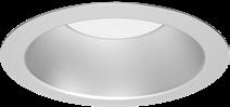
1. Install the luminaires with embedded controls
2. Install the nLight Wired wall switch
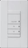
3. Connect the luminaires using standard CAT-5e cables and the controls devices will automatically discover each other and work (plug and play)
UL924 Sequence of Operation
The below information applies to all nLight AIR devices with an EM option.
• EM devices will remain at their high-end trim and ignore wireless lighting control commands, unless a normal-power-sensed (NPS) broadcast is received at least every 8 seconds.
• Using the CLAIRITY+ mobile app, EM devices must be associated with a group that includes a normal power sensing device to receive NPS broadcasts.
• Only non-emergency rPP20, rLSXR, rSBOR, rSDGR, and nLight AIR luminaires with version 3.4 or later firmware can provide normal power sensing for EM devices. See specification sheets for control devices and luminaires for more information on options that support normal power sensing.
Wireless Embedded Controls
1. Install the luminaires with embedded controls
2. Install the nLight AIR battery-powered wall switch
3. Use CLAIRITY+ mobile app to pair the fixtures with the wall switch and if desired, customize the sensor settings
FEATURES & SPECIFICATIONS
INTENDED USE — The CLX is a linear lighting solution that is available in multiple lengths, lumen packages and distributions. Designed for versatility, the CLX can address virtually any indoor lighting need. The CLX is also offered in standard and high efficacy configurations and capable of being continuous row mounted or installed as a stand-alone fixture. Ideal for uplight and downlight in commercial, retail, manufacturing, warehouse, and display applications. Certain airborne contaminants can diminish the integrity of acrylic and/or polycarbonate. Click here for Acrylic-Polycarbonate Compatibility table for suitable uses.
CONSTRUCTION — Channel and cover are formed from code-gauge cold-rolled steel. Housing and lens endcaps are injection molded plastic to provide a more architectural look and feel. The endcaps come standard with a 7/8" knock out for continuous mounting but can be ordered without.
Finish: Paint options include high-gloss, baked white polyester (WH), galvanized (GALV), matte black (MB) and smoke gray (SKGY). Five-stage iron phosphate pre-treatment ensures superior paint adhesion and rust resistance.
OPTICS — Offered with acrylic lens and less lens configurations. Provides a choice of optical distributions including, wide, narrow, and aisle.
Models with wide diffuse lens provide up to 12% uplight. Please check the IES file for specific uplight value.
ELECTRICAL — Utilizes high-output LEDs integrated on a two-layer circuit board, ensuring cool-running operation. Optional internal pluggable wiring harness for reduced labor cost in row mounting applications. (See PLR_ ordering information on page 9.) Electronic LED driver is multi-volt input and 0-10V dimming standard (see Operational Data on page 6 for actual wattage consumption). This fixture is designed to withstand a maximum line surge of 2.5kV at 0.75kA combination wave for indoor locations, for applications requiring higher level of protection additional surge protection must be provided. Color Variation within 3-step MacAdam ellipse (3SDCM).
L70>100,000 hours at 25˚C.
LEDs provide nominal 80 CRI or 90 CRI at 3000 K, 3500 K,4000 K, or 5000 K. Lumen output up to 2,500 lumens per foot.
INSTALLATION — Fixture may be ceiling or wall mounted (with or without THCLX hanger or angle mounted with CLXANGBKT), pendant or stem mounted with appropriate mounting options.
WARNING — Removing the lens and opening the fixture during installation exposes the LEDs, putting them at risk for damage.
If you plan to surface mount the fixture, we recommend using the THCLX. This eliminates the need to open the fixture.
If you plan to continuous row mount, we recommend using the PLR wiring harness option. This eliminates the need to open the fixture.
Damage to the LEDs caused during installation will not be covered under the warranty.
LISTINGS — CSA certified to US and Canadian safety standards. For use in damp locations between -4°F (-20°C) and 104°F (40°C). Optional High Ambient (HA) ranging to 122°F(50°C) available on certain lumen packages (See ambient temperature chart for additional information).
DesignLights Consortium® (DLC) Premium qualified product and DLC qualified product. Not all versions of this product may be DLC Premium qualified or DLC qualified. Please check the DLC Qualified Products List at www.designlights.org/QPL to confirm which versions are qualified.
GOVERNMENT PROCUREMENT — BAA – Product with the BAA option qualifies as a domestic end product under the Buy American Act as implemented in the FAR and DFARS. Product with the BAA option also qualifies as manufactured in the United States under DOT Buy America regulations.
BABA – Build America Buy America: Product with the BAA option also qualifies as produced in the United States under the definitions of the Build America, Buy America Act. Please refer to www.acuitybrands.com/buy-american for additional information.
WARRANTY — 5-year limited warranty. This is the only warranty provided and no other statements in this specification sheet create any warranty of any kind. All other express and implied warranties are disclaimed. Complete warranty terms located at: www.acuitybrands.com/support/warranty/terms-and-conditions
Note: Actual performance may differ as a result of end-user environment and application. All values are design or typical values, measured under laboratory conditions at 25 °C. Specifications subject to change without notice.
Stock configurations are offered for shorter lead times:
Part Number
CLX L48 3000LM SEF FDL MVOLT GZ10 40K 80CRI WH 00191723525816
L48 3000LM SEF FDL MVOLT GZ10 50K 80CRI WH 00191723525885
L48 5000LM SEF FDL MVOLT GZ10 40K 80CRI WH 00191723525939
CLX L48 5000LM SEF FDL MVOLT GZ10 50K 80CRI WH 00191723525908
CLX L96 6000LM SEF FDL MVOLT GZ10 40K 80CRI WH 00191723525861
CLX L96 6000LM SEF FDL MVOLT GZ10 50K 80CRI WH 00191723525915
CLX L96 10000LM SEF FDL MVOLT GZ10 40K 80CRI WH 00191723525922
CLX L96 10000LM SEF FDL MVOLT GZ10 50K 80CRI WH 00191723525830
CLX L48 3000LM SEF RDL MVOLT GZ10 40K 80CRI WH 00191723525960
CLX L48 3000LM SEF RDL MVOLT GZ10 50K 80CRI WH 00191723525892
CLX L48 5000LM SEF RDL MVOLT GZ10 40K 80CRI WH 00191723525854
CLX L48 5000LM SEF RDL MVOLT GZ10 50K 80CRI WH 00191723525946
CLX L96 6000LM SEF RDL MVOLT GZ10 40K 80CRI WH 00191723525878
CLX L96 6000LM SEF RDL MVOLT GZ10 50K 80CRI WH 00191723525823
CLX L96 10000LM SEF RDL MVOLT GZ10 40K 80CRI WH 00191723525953
CLX L96 10000LM SEF RDL MVOLT GZ10 50K 80CRI WH 00191723525847
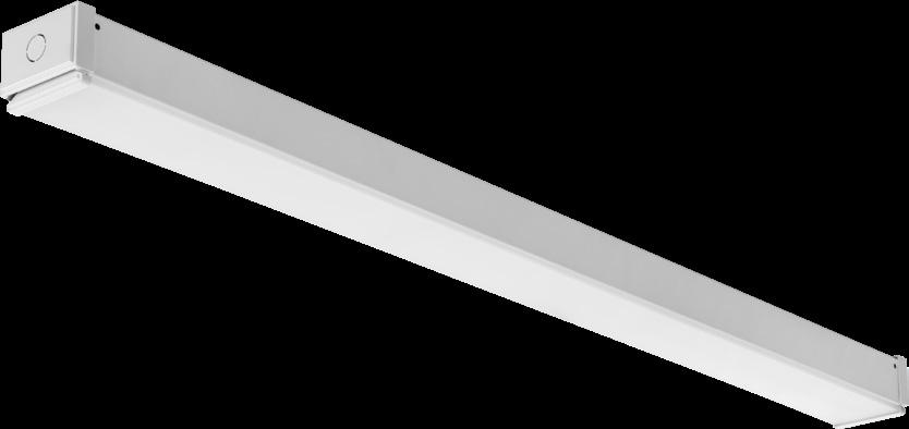
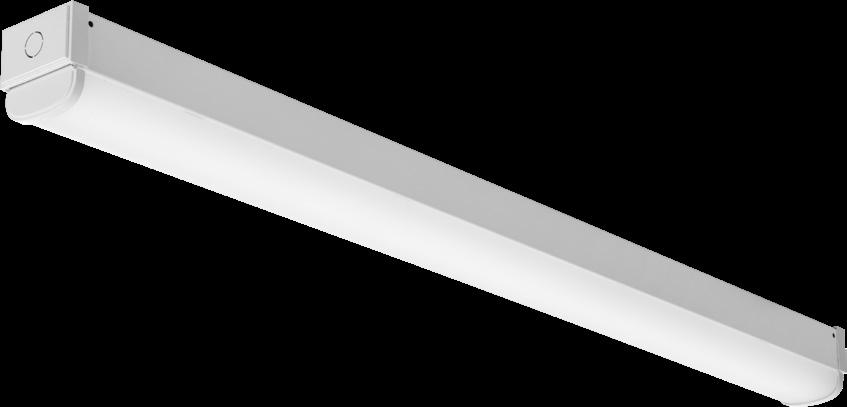
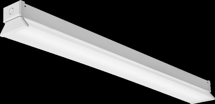
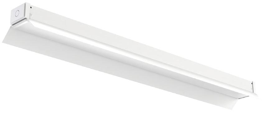
Capable Luminaire
This item is an A+ capable luminaire, which has been designed and tested to provide consistent color appearance and out-of-the-box control compatibility with simple commissioning when used with Acuity Brands controls products. All configurations of this luminaire are calibrated and tested to meet the Acuity Brands' specifications for chromatic consistency – including color rendering, color fidelity, and color temperature tolerance around standard CIE chromaticity coordinates.
To learn more about Acuity A+ standards, specifications, and testing visit www.acuitybrands.com/aplus
Items marked by a shaded background qualify for the Design Select program and ship in 15 days or less. To learn more about Design Select, visit www.acuitybrands.com/designselect *See ordering tree for details
Flat Diffuse Lens
Round Diffuse Lens
Wide Diffuse Lens
CLX with Reflector
1,500 lumens 2000LM 2,000 lumens
2500LM 2,500 lumens
3500LM 3,500 lumens
4500LM 4,500 lumens
5000LM 5,000 lumens
2250LM 2,250 lumens
3000LM 3,000 lumens
3750LM 3,750 lumens
5250LM 5,250 lumens 6750LM 6,750 lumens 7500LM 7,500 lumens 3000LM 3,000 lumens 4000LM 4,000 lumens 5000LM 5,000 lumens 7000LM 7,000 lumens 9000LM 9,000 lumens
10,000 lumens 6000LM 6,000 lumens
8,000 lumens
10,000 lumens
14,000 lumens
18,000 lumens 20000LM 20,000 lumens
(Blank) General ND Narrow ‡ WD Wide ‡ AD2 Aisle, 24° off center ‡
Options
E10W 10W Emergency battery pack, constant power, Certified in CA Title 20 MAEDBS, User selectable Self-Diagnostic, AC Activate with Integral Test Switch [LINK ] ‡
E10WSTAR Emergency battery pack, Enabled with STAR ‡
BGTD Generator transfer device, not available with E10W ‡
OCS 5', 18/3 Reloc selectable One Pass cable (fixture will bear dry location label) ‡
HA High ambient, for use in ambient temperatures up to 50°C ‡
EPNKO Decorative endplate, no knock out ‡
OUTCTR Wiring leads pulled through back center of fixture ‡
OUTEND Wiring leads pulled through end of fixture ‡
Cord Sets: ‡
CS1W 6' Staight blade plug, 120V ‡
CS3W NEMA twist-lock plug, 120V ‡
CS7W Staight blade plug, 277V ‡
CS11W NEMA twist-lock plug, 277V ‡
CS25W NEMA twist-lock plug, 347V ‡
CS97W NEMA twist-lock plug, 480V ‡
CS93W 600V SEOOW white cord, no plug (no voltage required) ‡
CS6WG16STOWD5D 6' white cord, 16/5, no plug, includes low voltage dimming wires (no voltage required) ‡
PLR__ Plug-in wiring, see page 9 for ordering information
PLR1G Plug-in wiring, single circuit, Ground
PLR1LVG Plug-in wiring, single circuit, low-voltage dimming, Ground ‡
RRL__ RELOC®-ready luminaire. See page 10 for ordering information
SPD Surge protection device, provides up to 6kV protection ‡
BAA Buy America(n) Act and/or Build America Buy America Qualified
nLight® Wireless:
NLTAIR2 RES7 nLight AIR Generation 2 enabled PIR integral occupancy sensor with automatic dimming photocell ‡
NLTAIR2 RES7EM nLight AIR Generation 2 enabled PIR integral occupancy sensor with automatic dimming photocell and UL924 Emergency operation, via power interrupt detection‡
NLTAIR2 RES7PDT nLight AIR Generation 2 enabled dual technology integral occupancy sensor with automatic dimming photocell‡
NLTAIR2 RES7PDTEM nLight AIR Generation 2 enabled dual technology integral occupancy sensor with automatic dimming photocell and UL924 Emergency operation, via power interrupt detection‡
NLTAIR2 RIO No sensor control ‡
NLTAIR2 RIOEM No sensor, Control Input function only and UL924 Emergency operation, via power interrupt detection ‡
nLight® Wired: N100 nLight® without lumen management
N100EMG nLight® without lumen management For use with generator supply EM power ‡
NES7 nLight® nES 7 PIR integral occupancy sensor ‡
NESPDT7 nLight® nES PDT 7 dual technology integral occupancy control ‡
NES7ADCX nLight® nES 7 ADCX PIR integral occupancy sensor with automatic dimming photocell ‡
NESPDT7ADCX nLight® nES PDT 7 dual technology integral occupancy sensor with automatic dimming photocell ‡
Individual controls: ‡
MSD7 PIR integral occupancy sensor
MSDPDT7 PDT 7 dual technology integral occupancy control
MSD7ADC PIR integral occupancy sensor with automatic dimming control photocell
MSDPDT7ADC PDT integral occupancy sensor with automatic dimming control photocell
WH White
GALVW Galvanized with white lens end caps
GALVB Galvanized with black lens end caps
MB Matte black
SKGYW Smoke gray with white lens end caps
SKGYB Smoke gray with black lens end caps
See Accessories and footnotes on next page
Design Select options indicated by this color background.
Accessories: Order as separate catalog number.
Mounting:
ZACVH M100
ZAC120
ZACFP120
ZACFPD120
ZAC240
ZACFP240
ZACFPD240
Option value
347V, 480V
Adjustable 10' aircraft cable with Y hanger (1 pair)
One adjustable aircraft cable with canopy 120", white
One adjustable aircraft cable with feed (3 conductor) and canopy, 120", white
One adjustable aircraft cable with feed (5 conductor) and canopy 120", white
One adjustable aircraft cable with canopy 240", white
One adjustable aircraft cable with feed (3 conductor) and canopy, 240", white
One adjustable aircraft cable with feed (5 conductor) and canopy 240", white
SQ_
Swivel stem hanger (specify length in 2" increments up to 48") Ships White ‡
THCLX __ Tong hanger (Must specify color) (one pair) ‡
CLXANGBKT ___ Angle bracket, (Must specify color) (one pair) ‡
HC36 M12 Hanger chain, 36" (1 pair)
Wireguards:
WGCLX24 __ 24" wireguard qty 1, (Must specify color) ‡
WGCLX36 __ 36" wireguard qty 1, (Must specify color) ‡
WGCLX48 __ 48" wireguard qty 1, (Must specify color) ‡
WGCLX48 __ J2 48" wireguard qty 2, (Must specify color) ‡
WGCLX48 __ J25 48" wireguard qty 25, (Must specify color) ‡
WGCLX48 __ J50 48" wireguard qty 50, (Must specify color) ‡
‡ Option Value Ordering Restrictions
Restriction
Voltage selected utilizes a step-down transformer. Not available with L24 when ordered with N100. Not available with E10W or BGTD options.
BGTD Not available with MVOLT, 208V or 240V. Not available with HA. Available with L48 or L96 only. Not available with E10W option. Not available with 208 or 240V. Not available Individual controls, NLight Wired, or NLight Wireless options.
CS1W, CS3W, CS7W, CS11W, CS25W, CS963W, CS97W Not available with BGTD option. Must specify voltage. Not available with PLR options.
CS6WG16STOWD5D Not available with Individual controls, nLight wired networking, nLight wireless networking, nLight wireless zone control options. Not available with PLR options.
Driver When continuous row mounting, fixtures must all have the same driver selection.
E10W Not available with HA. Not available with 347V or 480V. Not available with BGTD option. Requires SPD option. Not available with L24 or L36. Not available with L48 in combination with N100.
E10WSTAR
Not available with HA. Not available with 347V or 480V. Not available with BGTD option. Requires SPD option. Not available with L24 or L36. Not available with L48 in combination with N100.
EPNKO Not available OUTEND.
EZ1 Not available with HA option. Not available with 5000LM, 7500LM.
FDL, RDL, WDL
Only available with general distribution. Not available with CLXRN accessories. GZ1, GZ10
Not available with Individual controls, nLight wired networking, nLight wireless networking, nLight wireless zone control options.
HA Not available with L24, L26. Not available with BGTD option. Not available with EZ1. Only available with L48 3000/4000/5000LM and L96 6000/8000/10000LM.
HEF Not available with L48 3000LM and L96 6000LM
LUGR Not available with L36 length. Only available with WH finish. Not compatible with THCLX Hanger or wireguard accessories. LUGR option required for some DLC premium qualifications - Please check the DLC Qualified Products List to determine if LUGR option is necessary to meet requirement. If mounting in continuous rows, ensure all models ordered with LUGR option if required on any configuration to ensure rows match in form factor. LUGR reflectors ship in standard fixture carton and are not sold as separate accessory - this option MUST be specified as part of the CLX model number.
MSD7, MSDPDT7, MSD7ADC, MSDPDT7ADC Not available with any other control option. Requires EZ1. Sensor housing will be the same color as lens end caps.
N100, N100EMG nLight EMG option requires a connection to existing nLight network. Power is provided from separate N100 enabled fixture. ND, WD, AD2 Not available with CLXRN accessories. Available L/LENS only. NES7, NESPDT7, NES7ADCX, NESPDT7ADCX Not available with any other control option. Requires EZ1. Requires N100 or N100EMG option, N100EMG with NES7 requires RFA. Sensor housing will be the same color as lens end caps.
NLTAIR2 RES7(EM), NLTAIR2 RES7PDT(EM), NLTAIR2 RIO(EM) Sensor housing will be the same color as lens end caps. For EM, see UL924 Sequence of Operation chart below.
OCS Must specify voltage.
OUTCR Not available with L24. Not available with PLR options.
OUTEND Not available with PLR options.
PLR1LVG Not available with Individual controls, NLight Wired, or NLight Wireless options. Refer to page 9 for more PLR details. Not available with cord set options.
SBLW, SBLMB, SBLGV, SBLSKGY When ordered with L24 only available with 1500LM or 2000LM in combination with GZ10 driver. Not for use with THCLX, CLXANGBKT or WGCLX accessories. Not available with RDL lens options.
SEF Not available with EZ1 when ordered with L24 with 5000LM or L36 with 7500LM.
SPD Required with E10W, BGTD.
THCLX __, CLXANGBKT ___ Not available with louver or wireguards. THCLX__ not available with LUGR.
Wireguards Not for use with LUGR option. For L96 fixtures, use qty 2 48" wireguards.
SQ No available with L24 or L36
UL924 Sequence of Operation
The below information applies to all nLight AIR devices with an EM option.
• EM devices will remain at their high-end trim and ignore wireless lighting control commands, unless a normal-power-sensed (NPS) broadcast is received at least every 8 seconds.
• Using the CLAIRITY+ mobile app, EM devices must be associated with a group that includes a normal power sensing device to receive NPS broadcasts.
Only non-emergency rPP20, rLSXR, rSBOR, rSDGR, and nLight AIR luminaires with version 3.4 or later firmware can provide normal power sensing for EM devices. See specification sheets for control devices and luminaires for more information on options that support normal power sensing.
OPTIONS AND ACCESSORIES
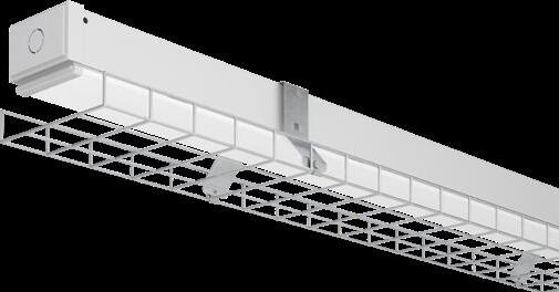
Wireguard Ships separately from fixture: 96" fixture requires two WGCLX48. Order as: WGCLX24__ WGCLX36__ WGCLX48__
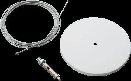
Aircraft Cable with Canopy Available in 120" or 240" Order as: ZAC120 ZAC240
HANGER CHAIN
36" chain with Y hanger. ships as a pair Order as: HC36
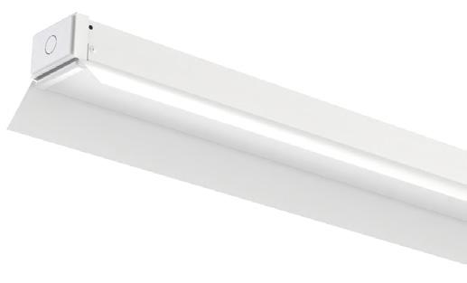
LUGR glare reflector NOT available as accessory - must be specified as part of the fixture nomenclature. See ordering notes on page 3.
ZACVH HANGER 10' Aircraft cable with Y hanger. Order as: ZACVH
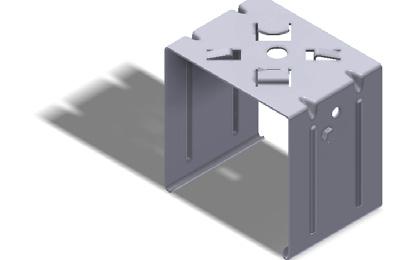
Tong hanger Ships as a pair Order As: THCLX__
DIMENSIONS
PALLET DIMENSIONS
SENTRY EMERGENCY BATTERY PACKS
Note: For emergency lumen output of specific model, please consult factory. One board will be illuminated during emergency operation.
Emergency Battery Pack Options - Field Installable
All the above are UL Listed products that are certified for field install external/remote to the fixture.
*Minimum delivered lumen output to assist in product selection for increased fixture mounting height. The CP10 delivered emergency illumination outperforms legacy 1400 lumen fluorescent emergency ballast. Please contact us at techsupport@iotaengineering.com for any Emergency Battery related questions.
Enabled with STAR
Emergency Lighting with Self-Testing Automated Reporting (STAR), enables self-testing and automated reporting to aid in life safety code compliance. Build your solution and choose your preferred deployment from Mobile STAR, where test data is logged in each individual unit and broadcast to the ClAIRity™+ app, or Connected STAR, where test data is logged in the STAR Gateway by IOTA® and emailed directly. Leave the ladders, disruptions and written records behind with emergency lighting solutions with STAR!
Life Safety Code NFPA 101 testing and reporting requirements for emergency lighting include:


Testing for 30 seconds every 30 days
Testing for 90 minutes once a year
Record keeping and to report to the authority having local jurisdiction
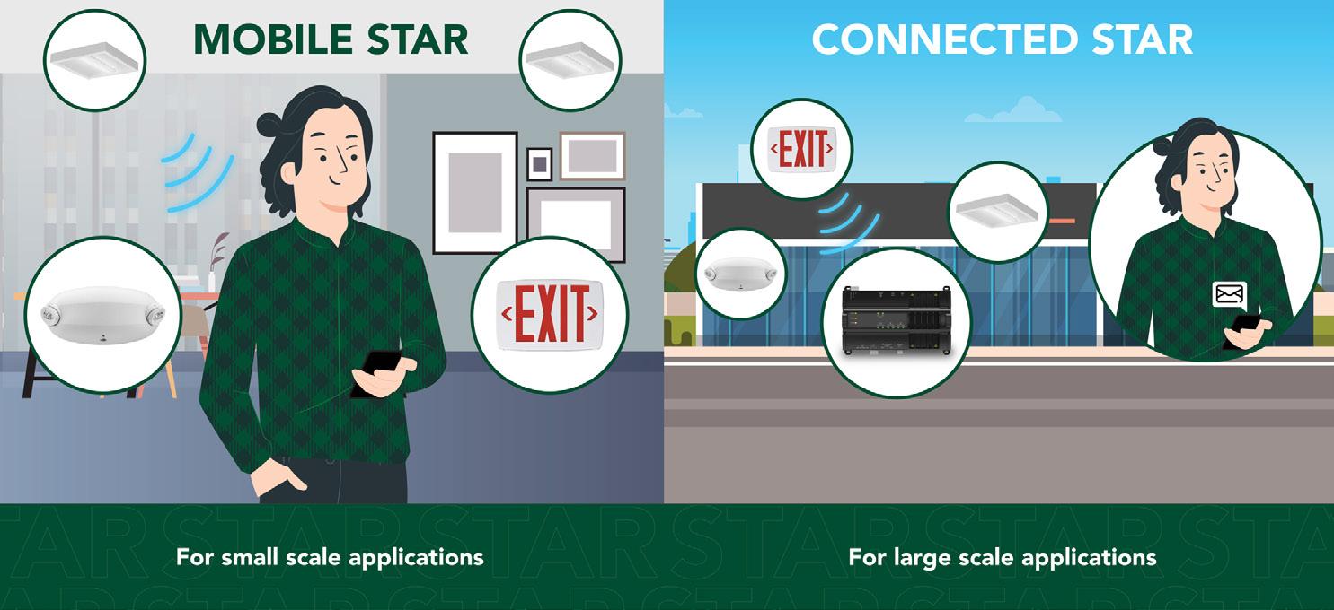
CLX CHARACTERISTICS
Note: For wattage by configuration, please reference the CLX Operational Data Document
Lumen Package UGR Values of CLX L24 @ 80CRI and 3500K
UGR varies based on luminaire options and is affected by application dependent parameters. Numbers depicted here are considered “Luminaire-UGR and/or “Point-UGR” values. To
(“Application-UGR”), a full lighting design layout should be completed with the selected luminaire configuration for each application
UGR varies based on luminaire options and is affected by application dependent parameters. Numbers depicted here are considered “Luminaire-UGR and/or “Point-UGR” values. To determine a more precise maximum UGR value (“Application-UGR”), a full lighting design layout should be completed with the selected luminaire configuration for each application
Lumen Package
UGR Values of CLX L48 @ 80CRI and 3500K
Lumen Package
UGR varies based on luminaire options and is affected by application dependent parameters. Numbers depicted here are considered “Luminaire-UGR and/or “Point-UGR” values. To determine a more precise maximum UGR value (“Application-UGR”), a full lighting design layout should be completed with the selected luminaire configuration for each application
UGR varies based on luminaire options and is affected by application dependent parameters. Numbers depicted here are considered “Luminaire-UGR and/or “Point-UGR” values.
a full lighting design layout should be completed with the selected luminaire configuration for each application
Lumen Package
AMBIENT TEMPERATURE RATINGS
RRL - RELOC®-Ready Luminaire
• RRL connectors can be used with Quick-Flex®, System 820 and OnePass® systems.
Load side of connector factory installed to luminaire.
4-pole mating connector with push-in terminations allows for simple installation.
Touch-safe design on both halves meets UL/CSA requirement.
Wiping contact design allows safe disconnect under load.
ORDERING INFORMATION Lead times will vary depending on options selected. Consult with your sales representative.
RRL RELOC®-ready luminaire A Hot conductor wired to position #1 (phase A)
B Hot conductor wired to position #2 (phase B)
C Hot conductor wired to position #3 (phase C) 1
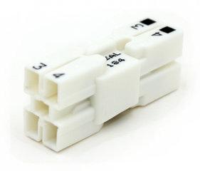
C12S Ballast/driver wired to pin position #1 (120V, 277V, 347V - Phase A). Low voltage wire (positive/purple) (data1) wired to pin position #2. Low voltage wire (common/gray) (data2) wired to pin position #3 2
Compatible RELOC® Cables for Industrial Luminaires (ordered and shipped separately)
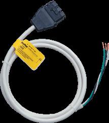
Notes
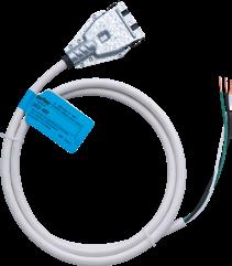
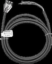
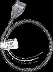
1 C, ABE, and C12S options are not used with Quick-Flex QFC, QSFC, QPT, and QD.
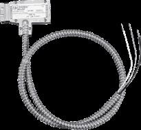
2 RRLC12S option is to be used with the OnePass OCU, OCS, OD, OFC and OD for 0-24V integrated single-circuit or 0-10V low voltage controls applications. Not available with integral dimming sensors.
PLUG-IN WIRING INFORMATION
Advanced plug-in system with two-circuit capability. Available on industrial and strip products and a variety of architectural products mounted in continuous rows. PLR22 (2-circuit) and crossover harness switches hot circuit serving next fixture in row.
Reduces fixture types on job for alternating circuit applications (see example below.)
Easy one-step installation, saves up to 35% on labor costs. Expanded switching flexibility helps save energy.
Rows can be 50% longer with two-circuit systems. Polarized, lock-together nylon connectors prevent miswiring in the field. #12 THHN conductor, rated 600V, 90°C. White neutral wire included. Grounding accomplished by fixture in-row connectors.
CSA certified systems available with up to 2 circuits. G ground required. Not for use with dedicated emergency circuits.
Note: Specifications subject to change without notice.
ORDERING INFORMATION Lead times will vary depending on options selected. Consult with your sales representative.
(blank) Not required for PLR22 (blank) Not required for PLR22
1 Black (blank) Not required for PLR1
2 Black and red Circuits to which driver is connected (blank) Not required for PLR22
Black wire B Red wire
Typical Applications
Notes:
When specifying PLR1, you will not specify A or B as there is only a single hot wire which would be black in color.
• Multiple-circuit and single-circuit for longer continuous rows
• Multiple-circuit with alternating fixtures on separate circuits and 2-circuit PLR22 Multiple circuit with night-lights located along row as desired
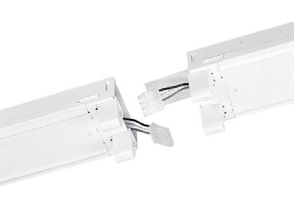
FEATURES & SPECIFICATIONS
INTENDED USE — Ideal for applications requiring attractive, quick-installation exit signs and low energy consumption. Certain airborne contaminants can diminish the integrity of acrylic and/or polycarbonate.
Click here for Acrylic-Polycarbonate Compatibility table for suitable uses.
CONSTRUCTION — Engineering-grade thermoplastic housing is impact-resistant, scratch-resistant, and corrosion-proof. UL94V-0 flame rating. UV-stable resin resists discoloration from natural and man-made light sources.
4 SKUs in 1: LQM: Standard with Red/Green Color Selection & AC/Battery Back-Up (EL) switch takes the guess work out of ordering. LQM EL HO: Standard with Nickel Cadmium battery back with remote capacity. LQM EL SD: Self Diagnostic Testing automatically performs a 5 minute self-diagnostic test every 30 days and 90 minutes annually.
3 Color Finishes: Available in white housing with white faceplate, black housing with black faceplate or black housing with brushed silver faceplate providing an upgraded aesthetic.
Face Standard: LQM ships with an extra faceplate to quickly convert from single to double face exit sign depending on the application. Directional chevrons can be easily removed and reinserted depending on the application.
Quick & Clean Installation: Standard with a quick mount canopy enabling faster installation, while leaving no hardware visible from the floor.
Letters 6" high with 3/4" stroke, with 100 ft. viewing distance rating, based upon UL924 standards. U.S. Patent No. 5,526,251; 5,611,163; 5,739,639; 5,954,423; 5,988,825; 6,152,581; D383,501; D495,751 and 6,502,044.
OPTICS — LEDs operate in normal (AC input) and emergency (Battery Back-up) mode for a minimum of 90 minutes.
The typical life of the exit LED lamp is >5 years, based on 24/7 operation.
ELECTRICAL — MULTI VOLT 120-277VAC, 50/60hz.
LQM: Equipped with an AC/Battery Back-Up (EL) internal switch. This gives the installer the ability to select the AC mode when the building is using a generator or inverter to provide emergency power to the sign or simply switch to Battery mode when these systems are not present, providing 90-minutes battery capacity. (U.S. Patent No. 12,422,115 B2).
Sign ships standard in AC mode. Sign ships with the battery included.
LQM: 1.2V, 900mAH Ni-Cad Battery
LQM EL HO: Equipped with sealed, maintenance-free nickel-cadmium battery providing 90-minutes capacity to emergency lamps.
LQM EL HO: 7.2V, 1200mAh Ni-Cad Battery. Provides 2.4W of Remote Capacity.
LQM EL SD: 4.8V, 300mAh Ni-Cad Battery.
LQM EL HO SD: 3.6V, 1800mAh Ni-Cad Battery. Provides 2.4W of Remote Capacity.
LQM EL SD: Self-diagnostic testing (EL Option Only). Units with this option automatically perform a 5-minute self-diagnostic test of the charging electronics, battery, and lamps every 30 days, and a 90-minute test every year. First self-test occurs within 15 days of continuous AC Power and annual test after 180 days of continuous AC power. SD performs a diagnostic evaluation of LED light source, AC to DC transfer, charging and battery condition.
AELR option: STAR (Self-testing Automated Reporting) radio transmits monthly and annual test results and diagnostics information for automated reporting requirements. For more information visit AcuityBrands.com/STAR INSTALLATION — Mounting canopy allows for top, back or end mounting. Back mount standard for single face only. Canopy design uses cam locking pin to secure sign to canopy with no visible hardware seen from the floor. Ships as a single sided exit with additional face plate and red/green color panels to easily convert from single face exit to double face exit.
Directional chevrons can be easily removed and reinserted depending on the application.
LISTINGS — UL damp location listed 50°-104°F (10°-40°C) standard. Meets UL924, NFPA 101 (current Life Safety Code), NEC, California Energy Commission Title 20 section 1605.3 (W)(4) and OSHA illumination standards. Meets all applicable FCC Title 47, Part 15, Subpart B requirements for exits not containing self-diagnostics (SD) option. Meets all applicable FCC Title 47, Part 15, Subpart A requirements for SD option. NOM certified. BUY AMERICAN ACT — BAA – Buy America(n) Act: Product with the BAA option qualifies as a domestic end product under the Buy American Act as implemented in the FAR and DFARS. Product with the BAA option also qualifies as manufactured in the United States under DOT Buy America regulations.
Please refer to www.acuitybrands.com/buy-american for additional information.
WARRANTY — 5-year limited warranty. (Battery is prorated.) This is the only warranty provided and no other statements in this specification sheet create any warranty of any kind. All other express and implied warranties are disclaimed. Complete warranty terms located at: www.acuitybrands.com/support/warranty/ terms-and-conditions
Note: Actual performance may differ as a result of end-user environment and application. All values are design or typical values, measured under laboratory conditions at 25 °C. Specifications subject to change without notice.
† Exit Signs Certified in the CA Title 20 Appliance Efficiency Database.
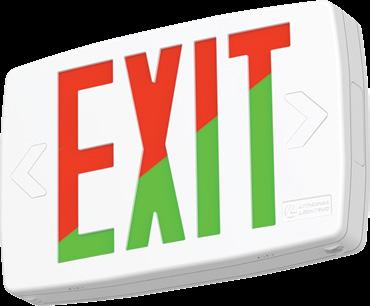
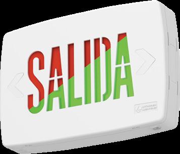
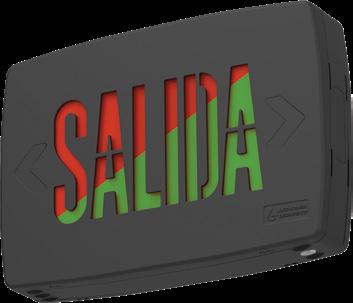
Brushed
LQM Red/Green Selectable LED, Quantum®
For shortest lead times, configure product using bolded options.
battery
Notes
LED indoor remote head, square, ivory white, .75W, 3.6V-12V voltage sensing 9 ERE W T SQ M12 Twin, LED indoor remote head, square, ivory white, 1.5W, 3.6V-12V voltage sensing 9 ERE GY SGL WP SQ M12 Single, LED weather-proof remote head, square, gray, 1W, 3.6V-12V voltage sensing 9 ERE GY T WP SQ M12 Twin, LED weather-proof remote head, square, gray, 2W, 3.6V-12V voltage sensing 9
Enabled with STAR
Emergency Lighting with Self-Testing Automated Reporting (STAR), enables self-testing and automated reporting to aid in life safety code compliance. Build your solution and choose your preferred deployment from Mobile STAR, where test data is logged in each individual unit and broadcast to the ClAIRity™+ app, or Connected STAR, where test data is logged in the STAR Gateway by IOTA® and emailed directly. Leave the ladders, disruptions and written records behind with emergency lighting solutions with STAR!
(blank) None HO High-output 2 SD Self-diagnostics 3
AELR Automatic Emergency Lighting Reporting 4
BAA Buy America(n) Act Compliant 5 SALIDA Salida signage, NOM standard 10
1 Dual circuit operation. Both circuits can be energized at the same time. UL Listed as emergency lighting. Not available with EL operation. Not available with HO, SD, AELR, BAA or SALIDA options.
2 EL and HO must be ordered in combination.
3 Must be ordered with EL operation. Not available with X2 operation.
4 Must be ordered in combination with EL and SD.
5 BAA option not available with X2 option. Only available with white housing.
6 See spec sheet ELA-WG
7 See spec sheet ELA-Stemkits
8 Only available with EL operation with HO option. The LP220L is the only remote lamp type compatible with LQM with HO option. See spec sheet ELMRE or ELMRW
9 Only available with EL operation with HO option. See spec sheet ERE
10 SALIDA only available in white or black housing. NOM standard. Not available with BAA or AELR options, or X2 operation. UL48 electric listing only. SALIDA stencil does not meet UL924 listing.
Life Safety Code NFPA 101 testing and reporting requirements for emergency lighting include:



Testing for 30 seconds every 30 days
Testing for 90 minutes once a year
Record keeping and to report to the authority having local jurisdiction
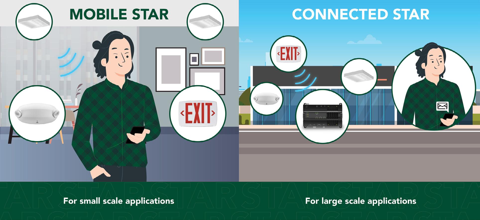
LQM Red/Green Selectable LED, Quantum®
SPECIFICATIONS
3.6V,
Notes
1. LED lamps operate in normal (AC input) and emergency (DC input) modes.
2. Based on 24/7 operation. The typical life of the exit LED lamp is >5 years.
3. At 77°F (25°C).
4. All life safety equipment, including emergency lighting for path of egress must be maintained, serviced and tested in accordance with all National Fire Protection Association (NFPA) and local codes. Failure to perform the required maintenance, service, or testing could jeopardize the safety of occupants and will void all warranties.
5. Temperature range where unit will provide capacity for 90 minutes. Higher and lower temperatures affect life and capacity.
EXTENDED RUN-TIME FOR HIGH-OUTPUT EXITS
MOUNTING
All
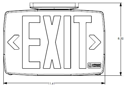
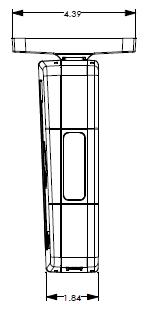
Notes
1. These are in addition to the lamp heads on the product.
ELM4L
Quantum® Contemporary Commercial LED Emergency Light
The Lithonia Lighting® Quantum® ELM4L Emergency Light is suitable for emergency lighting applications such as stairways and hallways. Its high performance LED lamp heads makes the ELM4L ideal for safely illuminating the path of egress for applications requiring attractive LED unit equipment with quick installation and unparalleled performance for 7.5’ to 24’ mounting heights. It can be wall or ceiling mounted and will provide 90 minutes of emergency power in the case of power loss.
FEATURES:
¡ Test switch and status indicator
¡ UL indoor damp location 50°F to 104°F (10°C to 40°C) listed standard
¡ For use with 120-277VAC input
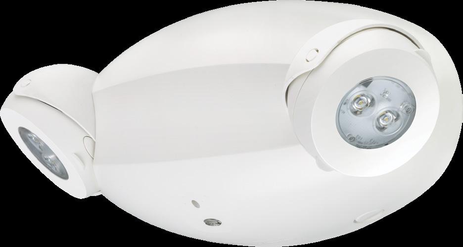

† Small Battery Chargers Certified in the CA Title 20 Appliance Efficiency Database.
Specifications
INTENDED USE:
Provides a minimum of 90 minutes illumination for the rated wattage upon loss of AC power to meet and exceed code required emergency lighting. Ideal for applications requiring attractive LED unit equipment with quick installation and unparalleled performance for mounting heights from 7.5’ TO 30’.
CONSTRUCTION:
The housing is a standard white thermoplastic with a compact and low-profile contemporary design. It is 5VA flame rated, impact-resistant, scratch-resistant and corrosion proof. The UV-stable resin resists discoloration from natural and man-made light sources. The back-plate contains a universal j-box mounting pattern to facilitate ease of installation on a wide variety of j-boxes and the front housing allows tool-less access for ease of maintenance.
OPTICS:
The typical life of the LED is 10 years. Two 3.3W LED Lamps.
ELECTRICAL:
Multi-voltage 120-277, 50/60hz standard. Emergency unit provided with test switch, status indicator and rechargeable battery. Sealed, maintenance-free nickel-cadmium battery provides 90 minutes of emergency power.
INSTALLATION:
Wall and ceiling mount. Tool-less removal of front cover from back-plate for ease of installation and maintenance.
LISTINGS:
UL damp location listed standard and wet location listed when used with the WPVS accessory, all at 50-104°F (10-40°C). Meets or exceeds all applicable requirements for UL 924, NFPA 101 (current Life Safety Code), NFPA 70 (NEC), NOM (Norma Oficial Mexicana), California Energy Commission Title 20 section 1605.3 (W)(4), FCC Title 47, Part 15, Subpart B and OSHA. List and labeled to comply with Canadian Standards C22.2 No. 141-10.
WARRANTY:
5-year limited warranty. Complete warranty terms located at: www.acuitybrands.com/support/customer-support/terms-and-conditions
Note: Actual performance may differ as a result of end-user environment and application. All values are design or typical values, measured under laboratory conditions at 25 °C. Specifications subject to change without notice.
Dimensions
(15.06)
Length: 13 3/8 (33.95)
Depth: 3 45/64 (9.39)
Height: 5 15/16 (15.06)
Weight: 3 lb (1.4kg)
All dimensions are inches (centimeters) unless otherwise indicated.
Spacing guidelines
Retail open area: 200' X 15' X 30' with 80/50/20 reflectances 10'
Notes:
1. Also meets the additional illumination requirements of NFPA 101: 1FC minimum and max/min ration of 40:1.
*Note: To see complete photometric report or download the .ies file for this product, visit Lithonia Lighting ELM4L and ELM6L home page.
Example of multiple ELM4L luminaires illuminating a 3' path of egress.
Example of single ELM4L illuminating a 3' path of egress.
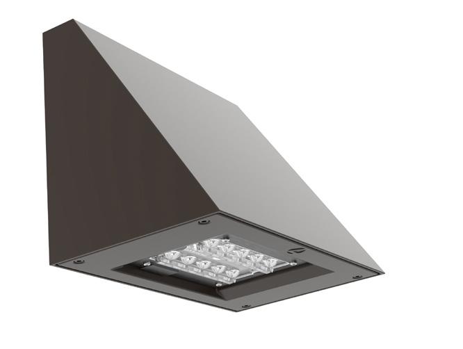
WDGE2 LED
Introduction
The WDGE LED family is designed to meet specifier’s every wallmounted lighting need in a widely accepted shape that blends with any architecture. The clean rectilinear design comes in four sizes with lumen packages ranging from 1,200 to 25,000 lumens, providing a true site-wide solution. Embedded with nLight® AIR wireless controls, the WDGE family provides additional energy savings and code compliance.
WDGE2 with industry leading precision refractive optics provides great uniform distribution and optical control. When combined with multiple integrated emergency battery backup options, including an 18W cold temperature option, the WDGE2 becomes the ideal wall-mounted lighting solution for pedestrian scale applications in any environment.
*See ordering tree for details
WDGE LED Family Overview
Ordering Information
E10WH Emergency battery backup, Certified in CA Title 20 MAEDBS (10W, 5°C min)
E20WC Emergency battery backup, Certified in CA Title 20 MAEDBS (18W, -20°C min)
PE Photocell, Button Type8
DMG 0-10V dimming wires pulled outside fixture (for use with an external control, ordered separately)9
BCE Bottom conduit entry for back box (PBBW). Total of 4 entry points.
CCE Coastal Construction7
Standalone Sensors/Controls
PIR Bi-level (100/35%) motion sensor for 8-15' mounting heights. Intended for use on switched circuits with external dusk to dawn switching.
PIRH Bi-level (100/35%) motion sensor for 15-30' mounting heights. Intended for use on switched circuits with external dusk to dawn switching
PIR1FC3V Bi-level (100/35%) motion sensor for 8-15' mounting heights with photocell pre-programmed for dusk to dawn operation.
PIRH1FC3V Bi-level (100/35%) motion sensor for 15-30' mounting heights with photocell pre-programmed for dusk to dawn operation.
Networked Sensors/Controls
NLTAIR2 PIR Embedded wireless controls by nLight with Passive Infrared Occ sensor and on/off photocell for 8-15' mounting heights.
NLTAIR2 PIRH Embedded wireless controls by nLight with Passive Infrared Occ sensor and on/off photocell for 15-30' mounting heights.
NLTAIREM2 PIR Embedded wireless controls by nLight with UL924 listed emegency operation, Passive Infrared Occ sensor and on/off photocell for 8-15' mounting heights
NLTAIREM2 PIRH Embedded wireless controls by nLight with UL924 listed emegency operation, Passive Infrared Occ sensor and on/off photocell for 15-30' mounting heights
See page 4 for out of box functionality
Accessories Ordered and shipped separately.
WDGEAWS DDBXD U WDGE 3/8inch Architectural Wall Spacer (specify finish)
WDGE2PBBW DDBXD U WDGE2 surface-mounted back box (specify finish)
NOTES
1 P0 option not available with sensors/controls.
2 P1-P4 not available with AMB and LW.
3 AMB and LW always go together.
4 70CRI only available with T3M and T4M.
5 347V and 480V not available with E10WH or E20WC.
6 Not qualified for DLC. Not available with emergency battery backup or sensors/controls.
7 For PBBW and AWS with CCE option, require an RFA.
8 PE not available in 480V or with sensors/controls.
9 DMG option not available with sensors/controls.
Lumen values are from photometric tests performed in accordance with IESNA LM-79-08. Data is considered to be representative of the configurations shown, within the tolerances allowed by Lighting Facts. Contact factory for performance data on any configurations not shown here.
Lumen Output in Emergency Mode (4000K, 80 CRI, T3M)
Lumen Ambient Temperature (LAT) Multipliers
Use these factors to determine relative lumen output for average ambient temperatures from 0-40°C (32-104°F).
Projected LED Lumen Maintenance
Data references the extrapolated performance projections for the platforms noted in a 25°C ambient, based on 10,000 hours of LED testing (tested per IESNA LM-80-08 and projected per IESNA TM-21-11).
To calculate LLF, use the lumen maintenance factor that corresponds to the desired number of operating hours below. For other lumen maintenance values, contact factory.
Photometric Diagrams
To see complete photometric reports or download .ies files for this product, visit the Lithonia Lighting WDGE LED homepage. Tested in accordance with IESNA LM-79 and LM-80 standards.
The emergency battery backup is integral to the luminaire — no external housing required! This design provides reliable emergency operation while maintaining the aesthetics of the product. All emergency battery backup configurations include an independent secondary driver with an integral relay to immediately detect loss of normal power and automatically energize the luminaire. The emergency battery will power the luminaire for a minimum duration of 90 minutes (maximum duration of three hours) from the time normal power is lost and maintain a minimum of 60% of the light output at the end of 90minutes.
Applicable codes: NFPA 70/NEC – section 700.16, NFPA
Control / Sensor Options
Motion/Ambient Sensor (PIR_, PIRH_)
Motion/Ambeint sensor (Sensor Switch MSOD) is integrated into the the luminaire. The sensor provides both Motion and Daylight based dimming of the luminaire. For motion detection, the sensor utilizes 100% Digital Passive Infrared (PIR) technology that is tuned for walking size motion while preventing false tripping from the environment. The integrated photocell enables additional energy savings during daytime periods when there is sufficient daylight. Optimize sensor coverage by either selecting PIR or PIRH option. PIR option comes with a sensor lens that is optimized to provide maximum coverage for mounting heights between 8-15ft, while PIRH is optimized for 15-40ft mounting height.
Networked Control (NLTAIR2)
nLight® AIR is a wireless lighting controls platform that allows for seamless integration of both indoor and outdoor luminaires. Five-tier security architecture, 900 MHz wireless communication and app (CLAIRITY™ Pro) based configurability combined together make nLight® AIR a secure, reliable and easy to use platform.
PIR1FC3V, PIRH1FC3V
PIR, NLTAIR2 PIRH, NLTAIREM2 PIR, NLTAIREM2 PIRH (out of box)
UL 924 Response – nLight AIR Devices with EM Option
• NLTAIREM2 devices will remain at their high-end trim and ignore wireless lighting control commands, unless a normal-power-sensed (NPS) broadcast is received at least every 8 seconds.
• Using the CLAIRITY+ mobile app, NLTAIREM2 devices must be associated with a group that includes a normal power sensing device to receive NPS broadcasts.
• The non-emergency devices, NLTAIR2 PIR and NLTAIR2 PIRH, with version 3.4 or later firmware can be used for normal power sensing.
Mounting, Options & Accessories
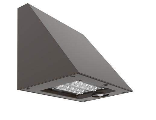
Motion/Ambient Sensor
D = 7"
H = 9" (Standalone controls)
11" (nLight AIR controls, 2" antenna will be pointing down behind the sensor)
W = 11.5"
AWS – 3/8inch Architectural Wall Spacer
D = 0.38"
H = 4.4"
W = 7.5"
FEATURES & SPECIFICATIONS
INTENDED USE
Common architectural look, with clean rectilinear shape, of the WDGE LED was designed to blend with any type of construction, whether it be tilt-up, frame or brick. Applications include commercial offices, warehouses, hospitals, schools, malls, restaurants, and other commercial buildings.
CONSTRUCTION
The single-piece die-cast aluminum housing integrates secondary heat sinks to optimize thermal transfer from the internal light engine heat sinks and promote long life. The driver is mounted in direct contact with the casting for a low operating temperature and long life. The die-cast door frame is fully gasketed with a one-piece solid silicone gasket to keep out moisture and dust, providing an IP66 rating for the luminaire.
FINISH
Exterior painted parts are protected by a zinc-infused Super Durable TGIC thermoset powder coat finish that provides superior resistance to corrosion and weathering. A tightly controlled multi-stage process ensures a 3 mils thickness for a finish that can withstand extreme climate changes without cracking or peeling. Standard Super Durable colors include dark bronze, black, natural aluminum, sandstone and white. Available in textured and non-textured finishes.
OPTICS
Individually formed acrylic lenses are engineered for superior application efficiency which maximizes the light in the areas where it is most needed. The WDGE LED has zero uplight and qualifies as a Nighttime Friendly™ product, meaning it is consistent with the LEED® and Green Globes™ criteria for eliminating wasteful uplight.
ELECTRICAL
Light engine consists of high-efficacy LEDs mounted to metal-core circuit boards to maximize heat dissipation and promote long life (up to L91/100,000 hours at 25°C). The electronic driver has a power factor of >90%, THD <20%. Luminaire comes with built in 6kV surge protection, which meets a minimum Category C low exposure (per ANSI/IEEE C62.41.2). Fixture ships standard with 0-10v dimmable driver.
PBBW – Surface-Mounted Back Box
Use when there is no junction box available.
D = 1.75"
H = 9"
W = 11.5"
INSTALLATION
A universal mounting plate with integral mounting support arms allows the fixture to hinge down for easy access while making wiring connections. The 3/8” Architectural Wall Spacer (AWS) can be used to create a floating appearance or to accommodate small imperfections in the wall surface. The ICW option can be used to mount the luminaire inverted for indirect lighting in dry and damp locations. Design can withstand up to a 1.5 G vibration load rating per ANSI C136.31.
LISTINGS
CSA certified to U.S. and Canadian standards. Luminaire is IP66 rated. PIR options are rated for wet location. Rated for -40°C minimum ambient. DesignLights Consortium® (DLC) Premium qualified product and DLC qualified product. Not all versions of this product may be DLC Premium qualified or DLC qualified. Please check the DLC Qualified Products List at www.designlights.org/QPL to confirm which versions are qualified. International DarkSky Association (IDA) Fixture Seal of Approval (FSA) is available for all products on this page utilizing 2700K and 3000K color temperature only and SRM mounting only.
GOVERNMENT PROCUREMENT
BABA – Build America Buy America: Product qualifies as produced in the United States under the definitions of the Build America, Buy America Act. Please refer to www.acuitybrands.com/buy-american for additional information.
WARRANTY
5-year limited warranty. This is the only warranty provided and no other statements in this specification sheet create any warranty of any kind. All other express and implied warranties are disclaimed. Complete warranty terms located at: www.acuitybrands.com/support/warranty/terms-and-conditions
Note: Actual performance may differ as a result of end-user environment and application. All values are design or typical values, measured under laboratory conditions at 25 °C. Specifications subject to change without notice.
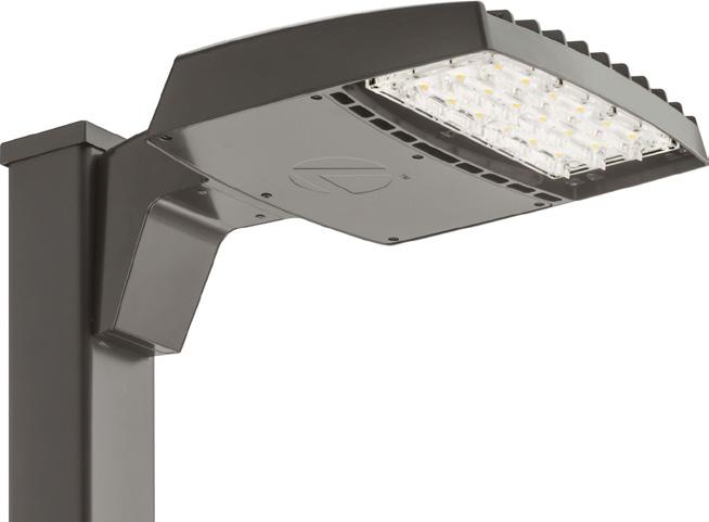
RSX1 LED Area Luminaire

Specifications
Height: 3.0" (7.6 cm) Main Body 7.2” (18.4 cm) Arm
Weight: (SPA mount): 22.0 lbs (10.0 kg)
Design Select options indicated by this color background.
Ordering Information
AFR Automotive Front Row
AFRR90 Automotive Front Row
Introduction
The new RSX LED Area family delivers maximum value by providing significant energy savings, long life and outstanding photometric performance at an affordable price. The RSX1 delivers 7,000 to 17,000 lumens allowing it to replace 70W to 400W HID luminaires.
The RSX features an integral universal mounting mechanism that allows the luminaire to be mounted on most existing drill hole patterns. This “no-drill” solution provides significant labor savings. An easy-access door on the bottom of mounting arm allows for wiring without opening the electrical compartment. A mast arm adaptor, adjustable integral slipfitter and other mounting configurations are available.
Items marked by a shaded background qualify for the Design Select program and ship in 15 days or less. To learn more about Design Select, visit www.acuitybrands.com/designselect
*See ordering tree for details
specific voltage for options as noted)
MA Mast arm adaptor (fits 2-3/8" OD horizontal tenon) IS Adjustable slipfitter (fits 2-3/8" OD tenon) 6
WBA Wall bracket 1
WBASC Wall bracket with surface conduit box
AASP Adjustable tilt arm square pole mounting 6
AARP Adjustable tilt arm round pole mounting 6
AAWB Adjustable tilt arm with wall bracket 6
AAWSC Adjustable tilt arm wall bracket and surface conduit box 6
Shipped Installed
HS House-side shield 7
PE Photocontrol, button style 8,9
PER7 Seven-wire twist-lock receptacle only (no controls) 9,10,11
SF Single fuse (120, 277, 347) 5
DF Double fuse (208, 240, 480) 5
SPD20KV 20KV Surge pack (10KV standard)
FAO Field adjustable output 9
DMG 0-10V dimming extend out back of housing for external control (control ordered separate) 9
Shipped Installed
*Standalone and Networked Sensors/Controls (factory default settings, see table page 9)
NLTAIR2 PIRHN nLight AIR generation 2, with Networked, Bi-Level motion/ambient sensor 9, 12, 13, 14
BAA Buy America(n) Act and/or Build America Buy America Qualified
CCE Coastal Construction15
*Note: NLTAIR2 PIRHN with nLight Air can be used as a standalone or networked solution. Sensor coverage pattern is affected when luminaire is tilted.
Shipped Separately (requires some field assembly)
EGS External glare shield 7
EGFV External
Hit the Tab key or mouse over the page to see all interactive elements.
Ordering Information
NOTES
1 Type 5 distribution is not available with WBA.
2 MVOLT driver operates on any line voltage from 120-277V (50/60 Hz).
3 HVOLT driver operates on any line voltage from 347-480V (50/60 Hz).
4 XVOLT driver not available with P1 or P2. XVOLT driver operates on any line voltage from 277V-480V (50/60 Hz). XVOLT not available with fusing (SF or DF) and not available with PE.
5 Single fuse (SF) requires 120V, 277V or 347V. Double fuse (DF) requires 208V, 240V or 480V.
6 Maximum tilt is 90° above horizontal.
7 It may be ordered as an accessory.
8 Requires MVOLT or 347V.
9 Two or more of the following options cannot be combined including PE, DMG, PER7, FAO and NLTAIR2 PIRHN. (Exception: PE and FAO can be combined; also PE and DMG can be combined.)
10 Compatible with standard twist-lock photocells for dusk to dawn operation or advanced control nodes that provide 0-10V dimming
External Shields
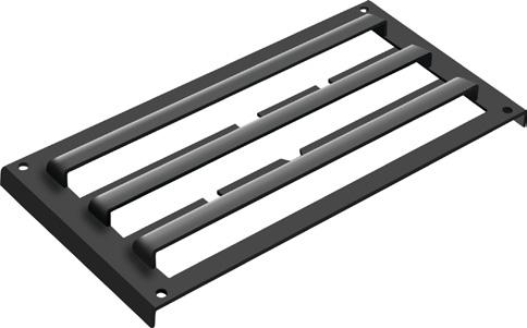
Pole/Mounting Informatiion
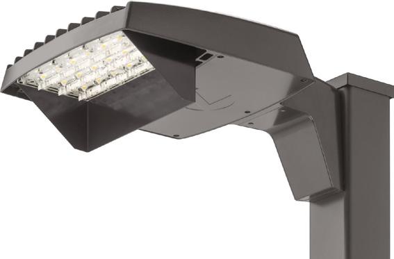
signals. Wire 4/Wire 5 wired to dimming leads on driver. Wire6/Wire7 capped inside luminaire. Twistlock photocell ordered and shipped as a separate line item from Acuity Brands Controls. See accessories. Shorting Cap included.
11 For units with option PER7, the mounting must be restricted to +/- 45° from horizontal aim per ANSI C136.10-2010.
12 Must be ordered with PIRHN.
13 Requires MVOLT or HVOLT.
14 Must be ordered with NLTAIR2. For additional information on PIRHN visit here
15 CCE option not available with WBA, WBASC, AASP, AARP, AAWB, AAWBSC, EGS, EGFV and BS.
16 Must be ordered with fixture for factory pre-drilling.
17 Requires luminaire to be specified with PER7 option. Ordered and shipped as a separate line item from Acuity
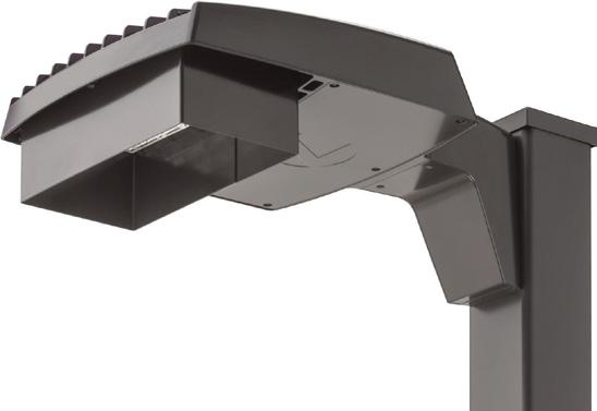
Accessories including bullhorns, cross arms and other adpaters are available under the accessories tab at Lithonia's Outdoor Poles and Arms product page. Click here to
Drill/Side Location by Configuration Type







Round Tenon Mount - Pole Top Slipfitters
Photometric Diagrams
To see complete photometric reports or download .ies files for this product, visit Lithonia Lighting’s RSX Area homepage
Isofootcandle plots for the RSX1 LED P4 40K. Distances are in units of mounting height (20’).
Performance Data
Lumen Ambient Temperature (LAT) Multipliers
Use these factors to determine relative lumen output for average ambient temperatures from 0-50°C (32-122°F).
Electrical Load
Projected LED Lumen Maintenance
30°C
35°C
40°C
Performance Data
Lumen Output
Lumen values are from photometric tests performed in accordance with IESNA LM-79-08. Data is considered to be representative of the configurations shown, within the tolerances allowed by Lighting Facts. Contact factory for performance data on any configurations not shown here.
133W
P2 72W
P3 109W
Dimensions & Weights
Luminaire Weight by Mounting Type
RSX1 with Round Pole Adapter (RPA)
Length: 22.8” (57.9 cm)
Width: 13.3” (33.8 cm)
Height: 3.0” (7.6 cm) Main Body 7.2” (18.4 cm) Arm
RSX1 with Mast Arm Adapter (MA)
Note: RPA — Round Pole mount can also be used to mount on square poles by omitting the round pole adapter plate shown here.
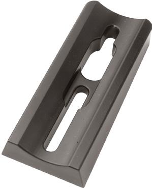
Length: 23.2” (59.1 cm)
Width: 13.3” (33.8 cm)
Height: 3.0” (7.6 cm) Main Body 3.5” (8.9 cm) Arm
RSX1 with Adjustable Slipfitter (IS) 7/8" KO - fits 1/2" NPT water- tight fitting
Length: 20.7” (52.7 cm)
Width: 13.3” (33.8 cm)
Height: 3.0” (7.6 cm) Main Body 7.6” (19.3 cm) Arm
Length: 23.6" (59.9 cm)
Width: 13.3” (33.8 cm)
Height: 3.0” (7.6 cm) Main Body
(22.6 cm) Arm
RSX1 with Wall Bracket with Surface Conduit Box (WBASC)
Length: 25.3” (64.3 cm)
Width: 13.3” (33.8 cm)
Height: 3.0” (7.6 cm) Main Body
(23.4 cm) Arm
RSX1 with Wall Bracket (WBA)
RSX1 with Adjustable Tilt Arm - Square or Round Pole (AASP or AARP)
Length: 25.3” (65.3 cm) AASP
26.3” (66.8 cm) AARP
Width: 13.3” (33.8 cm)
Height: 3.0” (7.6 cm) Main Body 7.2” (18.2 cm) Arm
NOTE: RPA - Round Pole mount can also be used to mount on square poles by omitting the round pole adapter plate shown here. 7/8" KO - fits 1/2" NPT water- tight fitting
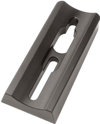
Notes
AASP: Requires 3.0" min. square pole for 1 at 90°. Requires 3.5" min. square pole for mounting 2, 3, 4 at 90°. AARP: Requires 3.2" min. dia. round pole for 2, 3, 4 at 90°. Requires 3.0" min. dia. round pole for mounting 1 at 90°, 2 at 180°, 3 at 120°.
RSX1 with Adjustable Tilt Arm with Wall Bracket (AAWB) Wall Bracket (WBA) Mounting Detail
7/8" KO - fits 1/2" NPT water- tight fitting
Length: 27.1” (68.8 cm)
Width: 13.3” (33.8 cm)
Height: 3.0” (7.6 cm) Main Body 8.9” (22.6 cm) Arm
RSX1 with Adjustable Tilt Arm with Wall Bracket and Surface Conduit Box (AAWSC)
3/4" NPT taps with plugs - Qty (4) provided
Length: 28.8” (73.2 cm)
Width: 13.3” (33.8 cm)
Height: 3.0” (7.6 cm) Main Body 9.2” (23.4 cm) Arm
Automotive Front Row - Rotated Optics (AFRL90/R90)
(Example: 2@180 - arrows indicate direction of light exiting the luminaire)
nLight Control - Sensor Coverage and Settings
nLight Sensor Coverage Pattern
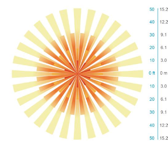
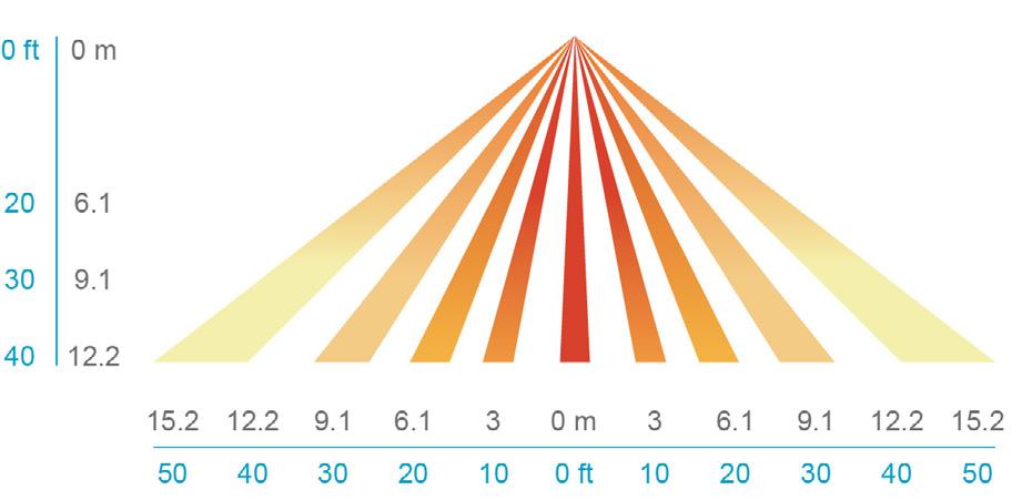
*Note: NLTAIR2 PIRHN default settings including photocell set-point, high/low dim rates, and occupancy sensor time delay are all configurable using the Clairity Pro App. Sensor coverage pattern shown with luminaire at 0°. Sensor coverage pattern is affected when luminaire is titled.
FEATURES & SPECIFICATIONS
INTENDED USE
The RSX LED area family is designed to provide a long-lasting, energy-efficient solution for the onefor-one replacement of existing metal halide or high pressure sodium lighting. The RSX1 delivers 7,000 to 17,000 lumens and is ideal for replacing 70W to 400W HID pole-mounted luminaires in parking lots and other area lighting applications.
CONSTRUCTION
The RSX LED area luminaire features a rugged die-cast aluminum main body that uses heatdissipating fins and flow-through venting to provide optimal thermal management that both enhances LED performance and extends component life. Integral “no drill” mounting arm allows the luminaire to be mounted on existing pole drillings, greatly reducing installation labor. The light engines and housing are sealed against moisture and environmental contaminants to IP66. The low-profile design results in a low EPA, allowing pole optimization. All mountings are rated for minimum 1.5 G vibration load per ANSI C136.31. 3G Mountings: Include SPA, RPA, MA, IS, AASP, and AARP rated for 3G vibration. 1.5G Mountings: Include WBA, WBASC, AAWB and AAWSC rated for 1.5G vibration.
FINISH
Exterior parts are protected by a zinc-infused Super Durable TGIC thermoset powder coat finish that provides superior resistance to corrosion and weathering. A tightly controlled multi-stage process ensures superior adhesion as well as a minimum finish thickness of 3 mils. The result is a high-quality finish that is warrantied not to crack or peel.
COASTAL CONSTRUCTION (CCE)
Optional corrosion-resistant construction is engineered with added corrosion protection in materials and/or pre-treatment of base material under super durable paint. Provides additional corrosion protection for applications near coastal areas. Finish is salt spray tested to over 5,000 hours per ASTM B117 with scribe rating of 10. Additional lead times apply.
OPTICS
Precision acrylic refractive lenses are engineered for superior application efficiency, distributing the light to where it is needed most. Available in short and wide pattern distributions including Type 2, Type 3, Type 3S, Type 4, Type 4S, Type 5, Type 5S, AFR (Automotive Front Row), and AFR rotated AFRR90 and ARFL90.
ELECTRICAL
Light engine(s) configurations consist of high-efficacy LEDs mounted on metal-core circuit boards and aluminum heat sinks to maximize heat dissipation. Light engines are IP66 rated. LED lumen maintenance is >L92/100,000 hours. CCT’s of 3000K, 4000K and 5000K (minimum 70 CRI) are available. Fixtures ship standard with 0-10v dimming driver. Class 1 electronic drivers ensure system power factor >90% and THD <20%. Easily serviceable 10kV surge protection device meets a minimum Category C Low operation (per ANSI/IEEE C62.41.2).
STANDARD CONTROLS
The RSX LED area luminaire has a wide assortment of control options. Dusk to dawn controls include MVOLT and 347V button-type photocells and NEMA twist-lock photocell receptacles.
nLIGHT AIR CONTROLS
The RSX LED area luminaire is also available with nLight® AIR for the ultimate in wireless control. This powerful controls platform provides out-of-the-box basic motion sensing with photocontrol functionality and is suitable for mounting heights up to 40 feet. No commissioning is required when using factory default settings that provide basic stand-alone motion occupancy dimming that is switched on and off with a built-in photocell. See chart above for motion sensor default out-of-box settings. For more advanced wireless functionality, such as group dimming, nLight AIR can be commissioned using a smartphone and the easy-touse CLAIRITY app. nLight AIR equipped luminaries can be grouped, resulting in motion sensor and photocell group response without the need for additional equipment. Scheduled dimming with motion sensor over-ride can be achieved when used with the nLight Eclypse. Additional information about nLight Air can be found here
INSTALLATION
Integral “no-drill” mounting arm allows for fast, easy mounting using existing pole drillings. Select the “SPA” option for square poles and the “RPA” option to mount to round poles. Note, the RPA mount can also be used for mounting to square poles by omitting the RPA adapter plate. Select the “MA” option to attach the luminaire to a 2 3/8” horizontal mast arm or the “IS” option for an adjustable slipfitter that mounts on a 2 3/8” OD tenon. The adjustable slipfitter has an integral junction box and offers easy installation. Can be tilted up to 90° above horizontal. Additional mountings are available including a wall bracket, adjustable tilt arm for direct-to-pole and wall and a surface conduit box for wall mount applications.
LISTINGS
CSA Certified to meet U.S. and Canadian standards. Suitable for wet locations. Rated for -40°C minimum ambient. DesignLights Consortium® (DLC) Premium qualified product and DLC qualified product. Not all versions of this product may be DLC Premium qualified or DLC qualified. Please check the DLC Qualified Products List at www.designlights.org/QPL to confirm which versions are qualified.
International Dark-Sky Association (IDA) Fixture Seal of Approval (FSA) is available for all products on this page utilizing 3000K color temperature only. U.S. Patent No. D882, 146S
GOVERNMENT PROCUREMENT
BAA – Buy America(n) Act: Product with the BAA option qualifies as a domestic end product under the Buy American Act as implemented in the FAR and DFARS. Product with the BAA option also qualifies as manufactured in the United States under DOT Buy America regulations. BABA – Build America Buy America: Product with the BAA option also qualifies as produced in the United States under the definitions of the Build America, Buy America Act. Please refer to www.acuitybrands.com/buy-american for additional information.
WARRANTY
5-year limited warranty. This is the only warranty provided and no other statements in this specification sheet create any warranty of any kind. All other express and implied warranties are disclaimed. Complete warranty terms located at: www.acuitybrands.com/support/warranty/terms-and-conditions
Note: Actual performance may differ as a result of end-user environment and application. All values are design or typical values, measured under laboratory conditions at 25 °C. Specifications subject to change without notice.
Lithonia
IVO™
IVO™ 4" Round Shallow Recessed Downlight
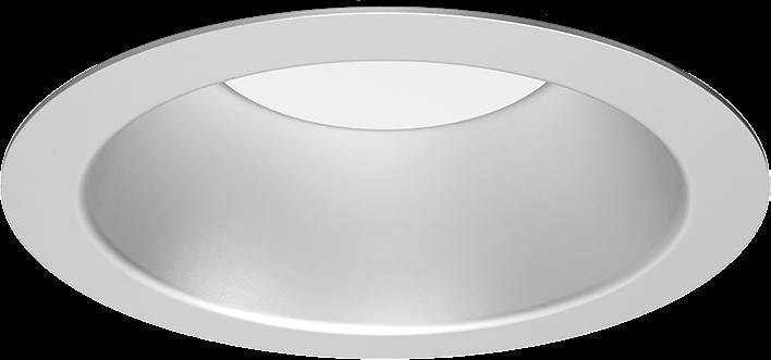
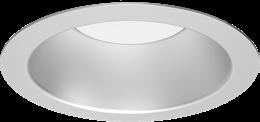
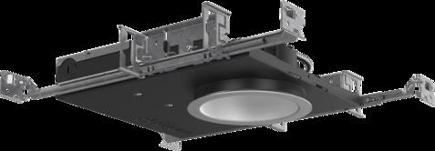
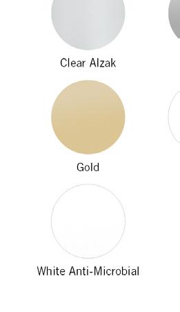
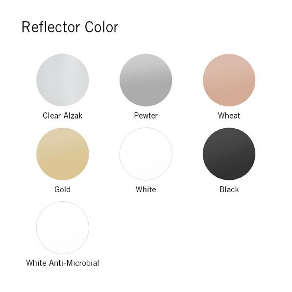
• Ultra Shallow recessed downlight fits in plenums as small as 2 inches above ceiling
• Perfect Color™ consistency within ½-step MacAdam Ellipse
• Bounding Ray™ optical design delivers low brightness apertures for a comfortable lighting experience
• 65° cutoff to source and source image

• Title 24, JA8 compliant Feature Set
Up to 90% lumen maintenance at 55,000 hours
Wet Location optional, covered ceiling ICAT is Spray Foam Compatible
• Exceptional color rendering with 80 CRI, 90 CRI, or 95 CRI minimum
• Batwing distributions with feathered edges to provide even illumination fixture-to-fixture
• Field adaptable with interchangeable optics and trims
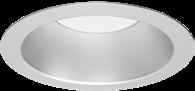



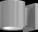
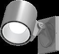
• ENERGY STAR® Certified product
Dimming (Forward/Reverse) (120V only)
DMX 7 DMX
DALI 7 DALI-2
NLIGHT Wired controls by nLight
NLTAIR2 Wireless controls by nLight Air
NLIGHTER Wired controls by nLight with UL924 listed emergency operation
NLTAIREM2 Wireless controls by nLight Air with UL924 listed emergency operation
NCH Non-IC Housing (new construction only) ICAT IC/Airtight Housing (new construction only). 2000LM max. Spray foam compatible.
CP Chicago Plenum CCEA Housing (new construction only).
RM Non-IC Remodel Housing (install from below). Not available with Emergency Pack options.
GR Gold Anodized
PR Pewter Anodized
WTR Wheat Anodized
WR 10,14 White Gloss (painted)
WMR 10 Soft White Matte (painted)
WRAMF 10 White Gloss with Anti-Microbial (painted)
BZR 10,14 Dark Bronze Gloss (painted)
TRALTBD 10,11,14 Trim RAL # (TBD for pricing only)
TCPC 10,14 Trim Custom Paint Color LD Matte Diffuse LS Specular LSS Semi Specular F Self Flanged (color matches trim) FL Flangeless (Drywall)
FLM Flangeless Millwork
FBL 12 Flange Only Black
FWR 13 Flange Only White
FRALTBD 11,14 Flange Only RAL FCPC14 Flange Only Custom Paint Color
Buy America(n) Act or
ACCESSORIES — order as separate catalog numbers (shipped separately)
IVO4SOPTC D MD U Field Replaceable Optic, Medium Distribution
IVO4SOPTC D MWD U Field Replaceable Optic, Medium Wide Distribution
IVO4SOPTC D WD U Field Replaceable Optics, Wide Distribution
GRA4/6.5IVO JZ Round goof ring adapter 4" ID, 6.5" OD
SCA4 Sloped ceiling adaptor. Degree of slope must be specified (5D, 10D, 15D, 20D, 25D, 30D). Ex: SCA4 10D. Refer to TECH-190 for details.
IVO4FLMKIT IVO 4" Round Flangeless in Millwork Ceiling Cutout Template (min. 1 required per install)
IVOFLMBIT IVO Flangeless in Millwork Straight Router Bit, 1/4" Shank with Bearing (optional)
ORDERING NOTES
1. 05LM only available with ELV or ZT. Not available with 347V.
2. 50K CCT is not available with 90CRI. 35K, 40K or 50K is not available with 95CRI.
3. 347 only available with ZT at MIN1 or MIN10. Not available with nLight devices or Emergency Options.
4. Refer to Tech-240 for compatible dimmers.
5. ZT is not available with DARK.
6. ELV only is only available with MIN1.
7. DMX and DALI are only available with DARK.
8. E7WR and GTD are not available with DMX, NLIGHT, NLTAIR2 NLIGHTER, NLTAIREM2, or with RM housing.
9. RM with SF is not available with DMX or nLight.
10. Not available with Trim Finish.
11. Replace with applicable RAL number and finish when ready to order. See RAL BROCHURE for available color options.
12. For use with different reflector flange colors only (i.e. AR, BZR, GR, PR, WTR, WR, WMR, WRAMF options). Not applicable with BR (black reflector) or FL (flangeless), TRALTBD or TCPC options.
13. For use with different reflector flange colors only (i.e. AR, BR, BZR, GR, PR, WTR options). Not applicable with WR, WMR, WRAMF (white reflector) or FL (flangeless), TRALTBD or TCPC options.
14. TRALTBD or TCPC are not compatible with FRALTBD or FCPC.
Dimensions in inches [centimeters]
1/2" clearance on all sides required from non-combustible materials in non-IC applications, unless marked spacing noted otherwise. Marked Spacing requires
clearance center-to-center x center to side building member x overhead to building member. New Construction Dimensions Standard New Construction Housing (NCH)
Trim Aperture: 4 5/16" (11)
Flanged Trim O.D.: 5 1/2" (14)
NCH with NLIGHT, NLTAIR2, NLIGHTER, NLTAIREM2, or DMX
IC Airtight (ICAT), Chicago Plenum (CP), or Emergency (E7WR) Housing (for E7WR with 20LM use Marked Spacing 24"x12"x1/2")
Generator Transfer Device (GTD) Housing
Remodel Dimensions
Dimensions in inches [centimeters]
1/2" clearance on all sides required from non-combustible materials in non-IC applications, unless marked spacing noted otherwise.
Trim Aperture: 4 5/16" (11)
Flanged Trim O.D.: 5 1/2" (14) Ceiling cutout (flangeless): 5 1/4" (13.3)
Remodel Construction (RM) Requires 2" of plenum height
Remodel Construction (RM) Driver Enclosure with Fuse (SF) Requires 3" of plenum height
Remodel Construction (RM) Driver Enclosures with Control Options Requires 3" of plenum height
How to Estimate Delivered Lumens in Emergency Mode
Delivered Lumens = 1.25 x P x LPW
P = Output Power/Wattage of Emergency Battery
LPW = Lumen per Watt rating of luminaire based on Ordering Code selections
Optical System
Bounding Ray™ optical design delivers top down flash for superior brightness control. Source and source image present simultaneously.
Unitized optical system has mechanical attachment of the light engine to the trim for optimized optical alignment.
Source regression delivers 65 degrees of visual cutoff to source and source image.
Patent pending optics are available in three (3) batwing distributions for optimal uniformity, free of shadows, hot spots or striations.
Optics are field interchangeable without tools via twist lock feature.
LED Light Engine
Proprietary light engines are custom binned to deliver perfect color consistency of 0.5 step MacAdam Ellipse fixture to fixture.
LED light engine is rated for L90 / 55,000 hours up to 2500 lumens and L80 / 55,000 hours at 3000 lumens.
Available in 80, 90, or 95 CRI minimum. 90 CRI has an R9 greater than 50. 95 CRI has an R9 greater than 80.
Trims
Trims are field interchangeable via twist lock mechanism.
Trims are available in nine (9) standard colors and three standard finishes that can be customized.
Electrical
Luminaire operates from a 50 or 60 Hz ±3 Hz AC line over a voltage ranging from 120 VAC to 347 VAC. The fluctuations of line voltage have no visible effect on the luminous output.
Luminaire has a power factor of 85% or greater at all standard operating voltages and full luminaire output.
EMI/RFI per FCC Title 47 CFR, Part 15, Class A rated. ELV Phase dimming Driver is Class B rated except when used with E7WR or at 15LM and above. Input wires are 18AWG, 600V minimum, solid copper.
Controls (Optional)
Luminaire is equipped with interface for nLight wired, meaning it has the ability to communicate over an nLight network. When wired, using CAT 5 cabling, with other nLight enabled sensors, power packs, or WallPods, an nLight control zone is created. Once linked to a Gateway, directly or via a Bridge, the zone becomes capable of remote status monitoring and control via SensorView software. Luminaire is equipped with interface for nLight Air, meaning it can communicate over the wireless nLight control platform. It pairs to other luminaires and wall switches through our mobile app, CLAIRITY+, which allows for single fixture control.
Dimming
The luminaire is capable of continuous dimming without perceivable stroboscopic flicker as measured by flicker index (ANSI/IES RP 16 10) over a range of 100 – 10%, 100 – 1.0% or 100 – 0.1% of rated lumen output with a smooth shut off function to step to 0%.
eldoLED LED drivers (EZT) conforms to IEEE P1789 standards. The driver is inaudible in 24dB environment, and stable when input voltage conditions fluctuate over what is typically experienced in a commercial environment.
Emergency Battery (Optional)
Self testing integral emergency battery (E7WR) provides a emergency lighting for a duration of 90 minutes to meet egress code requirements. Emergency battery is accessible from below the ceiling. Emergency battery is CEC T20 Compliant.
Capable Luminaire
Installation
Luminaire installs in 2" plenum depth ceiling (unless noted otherwise). Fixture is suitable for installation in ceilings from 5/8" to 2" in ceiling thickness via patented retention spring design.
Luminaire has telescopic mounting bars with maximum 24" and minimum 10 1/2" extension and 1 1/8" vertical adjustment (supplied separated).
Mounting brackets also work with C Channel from ¾" to 1 1/2", Flat Strap from ½" to ¾", Conduit up to ¾" in diameter, and ½" angle bar.
Luminaire is rated for up to (8) No. 12 AWG 90°C through branch circuit conductors.
Non IC rated luminaires shall be installed with 3" of clearance on all sides from insulation or 1/2" clearance on all sides from non combustible materials (unless marked spacing noted otherwise.)
IC rated luminaires can be installed in direct contact with insulation.
Construction
Luminaire features LED module with quick disconnect harness and strain relief for ease of inspection and service.
Servicing and maintaining the light engine, driver and branch circuit conductors is possible without tools from below the ceiling.
Luminaire is constructed with 20 gauge galvanized steel.
Listings
Fixtures are CSA certified to meet US and Canadian Standards. All fixtures manufactured in strict accordance with the appropriate and current requirements of the “Standards for Safety" to UL, damp location standard, or UL wet location, covered ceiling only, optional.
Photometrics
All photometry is conducted by IESNA standard LM 79 08 in an accredited lab. LEDs are tested to LM 80 standards. Lumen maintenance is calculated via TM 21.
GOVERNMENT PROCUREMENT
BAA – Product with the BAA option qualifies as a domestic end product under the Buy American Act as implemented in the FAR and DFARS. Product with the BAA option also qualifies as manufactured in the United States under DOT Buy America regulations.
BABA – Build America Buy America: Product with the BAA option also qualifies as produced in the United States under the definitions of the Build America, Buy America Act.
Please refer to www.acuitybrands.com/buy american for additional information.
Warranty
5 year limited warranty. This is the only warranty provided and no other statements in this specification sheet create any warranty of any kind. All other express and implied warranties are disclaimed. Complete warranty terms located at: www.acuitybrands.com/support/warranty/terms and conditions
Note:
Actual performance may differ as a result of end user environment and application.
All values are design or typical values, measured under laboratory conditions at 25 °C.
The product images shown are for illustration purposes only and may not be an exact representation of the product.
This item is an A+ capable luminaire, which has been designed and tested to provided consistent color appearance and out of the box control capability with simple commissioning when used with Acuity Brands controls products.
All configurations of this luminaire are calibrated and tested meet the Acuity Brands' specification for chromatic consistency including color rendering, color fidelity and color temperature tolerance around standard CIE chromaticity coordinates.
To learn more about A+, visit www.acuitybrands.com/aplus
Flangeless Installation
Gotham’s flangeless option utilizes a micro thin polymer mud ring that minimizes the amount of drywall compound required to finish the ceiling. The end result is a virtually undetectable flangeless downlight installation.
The polymer mud ring is installed independent of the of the recessed frame, therefore floating with the ceiling. This innovation minimizes any surface cracks during reflector installation, ceiling movement and any future service to the recessed frame, wiring, electronics, etc.
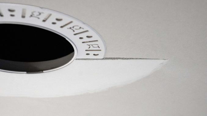
Partially finished mud ring, showing cross section detail.
Flangeless Millwork Installation
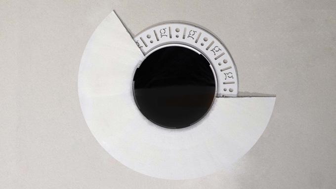
only

IVO’s Flangeless in Millwork solution makes installation easy and precise. First, cut a hole in the Wood Ceiling using the Millwork Cutout Template (sold separately). Second, once Housing and ceiling are mounted in place, insert sheet metal Millwork Adapter (provided) lining up edge of tab with bottom of ceiling. Third, secure in place using finishing nails (provided) then remove tabs from Millwork Adapter. Last, install Trim!
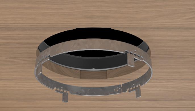
* ELV Minimum Dimming level depends on dimmer and dimmer load
Insert Millwork Adapter into precision cut hole.
An IVO downlight requires
approximately 3" of plaster to finish.
Secure with finishing nails.
IVO with flangeless trim
Insert Trim and Module.
MD Medium Beam
IVO4S D 20LM 35K 80CRI MD P AR LSS
Wattage: 22.4, Lumens: 1894, LPW: 85, S/MH: .86, Test No: 23-460-4P351
Medium Wide Beam
IVO4S D 20LM 35K 80CRI MWD P AR LSS
Wattage: 22.4, Lumens: 1929, LPW: 86, S/MH: .97, Test No: 23-561-1P351
WD Wide Beam
IVO4S D 20LM 35K 80CRI WD P AR LSS
Wattage: 22.4, Lumens: 1936.9, LPW: 87, S/MH: 1.1, Test No: 23-561-7P351
*UGR varies based on luminaire options and is affected by application dependent parameters. Numbers depicted here are considered “Luminaire UGR" and/or “Point UGR" values. To determine a more precise maximum UGR value (“Application UGR"), a full lighting design layout should be completed with the selected luminaire configuration for each application.
**Calculated using an AR (Clear reflector) with LSS (Semi Specular) finish
MWD
Single Lighting Controls Platform for Indoor & Outdoor Spaces
nLight® is your networked lighting controls platform, for indoor and outdoor applications, providing wired or wireless options. Scaling from room to campus-wide applications, it is the one platform that grows with your business today and tomorrow; to seamlessly address energy cost optimization, building code compliance, improved occupant comfort, and much more. nLight also interfaces with DALI®, BACnet®, DMX and additional third-party devices. nLightcontrols.com
Wired Embedded Controls
1. Install the luminaires with embedded controls
2. Install the nLight Wired wall switch
3. Connect the luminaires using standard CAT-5e cables and the controls devices will automatically discover each other and work (plug and play)
UL924 Sequence of Operation
The below information applies to all nLight AIR devices with an EM option.
• EM devices will remain at their high-end trim and ignore wireless lighting control commands, unless a normal-power-sensed (NPS) broadcast is received at least every 8 seconds.
Using the CLAIRITY+ mobile app, EM devices must be associated with a group that includes a normal power sensing device to receive NPS broadcasts.
• Only non-emergency rPP20, rLSXR, rSBOR, rSDGR, and nLight AIR luminaires with version 3.4 or later firmware can provide normal power sensing for EM devices. See specification sheets for control devices and luminaires for more information on options that support normal power sensing.
Wireless Embedded Controls
1. Install the luminaires with embedded controls
2. Install the nLight AIR battery-powered wall switch
3. Use CLAIRITY+ mobile app to pair the fixtures with the wall switch and if desired, customize the sensor settings