15 minute read
Bill Heard’s Cowley restoration


I started the restoration of my Great Grand Fathers 1928 Morris Cowley Colonial in March 2020. I contributed an article about the start of the restoration, in the June 2020 Klaxon edition, so I now continue with the challenge of restoring the motor. After I had freed up 2 stuck valves, I was able to turn the crank shaft over, to allow my brother & I to remove the springs from the pins holding the clutch plates onto the fly wheel. We then removed the gear box & delivered the motor to a Tauranga motor engineer. Then Covid struck.
The Motor Restoration Starts – May 2020
So after the first Covid lockdown when it was possible to visit the motor engineer, I called to check the progress, & we agreed that they would strip the engine & send the block to Rotorua, to dip into an acid bath to flush the water galleries & generally clean it. A couple of days later, I got a call from them to say that I had better call around as there were some issues. So around I went, & I was expecting to hear that the block was cracked. NO. A terrible repair had been made many years ago. One piston had been welded & another was in a poor state & bearings were badly worn. I returned days later with a box of old pistons & new valves & gudgeon pins, hoping that these parts would be machined to recondition the motor.
I had also mentioned earlier that I had a spare motor. Days later I was asked if I could take in the spare motor & would it be ok if the parts could be shared to make one motor. I said yes. Meantime I had joined the Bullnose Morris Club UK, where they had the factory records of the car, & the day that it was manufactured. I also found out that the car was a Colonial model, which had a wider wheel track & the larger Oxford motor (the Cowley had a bore of 69mm & the Oxford 75mm). So armed with this information, I visited the engineer & photographed both engine numbers & found out that the spare motor was the original one & decided that this was the one to be restored.

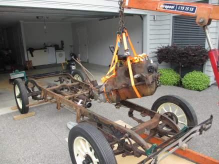
The Cowley motor is lifted off the chassis Broken pistons
So the days roll on by & I was asked if it was possible to obtain new pistons, valves & valve guides. So parts were purchased from the UK & Australia. Meantime the Tga motor engineer had made some progress on restoring the engine, & then he hit a road block - the new valve guides, valves & springs were fitted to the nice clean block, which had been through the acid bath & I was now asked if I could get new bearing shells for the conrods, plus the main bearings needed to be re-metalled, & as this is a specialist job, which in the past was only undertaken by a few people (most now deceased) he had to track someone down.
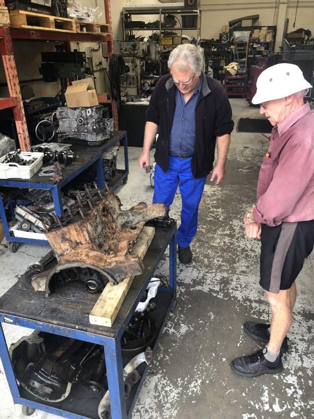
I am called into the Tauranga engineers workshop to get the bad news about the broken pistons
A retired man was eventually found who had the equipment, to Babbitt the main bearings, & he was booked in to visit the works sometime. It turned out that he went away on holiday & couldn’t be contacted, so I started asking club members if they knew who could Babbitt the bearings, & found out about a motor engineer in Levin who the Ford people use. I contacted Murray Horn & booked in the final restoration for approx early 2021. Then I approached my first engineer & we agreed that I would pick up all of the parts & he would machine the head & exhaust manifold. So I made 3 trips, & came home with 2 engines & boxes of parts! I got onto sorting out all of the parts. I had 2 blocks. The Cowley & the Oxford & a multitude of parts. 8 conrods, loose bearing shells, main bearings, 2 crank shafts & cam shafts, splined gears, an assortment of valves & valve guides & springs, 2 oil pumps, nuts & bolts, washers & things that I just didn’t know where they went. As I hadn’t pulled the engines apart, it was like working on a jig saw puzzle. I spent a day just trying to match the conrods, shells & big ends. They had to be matched & only went together one way, as the crankshaft is not directly below the cylinder but offset, & the big end caps have a slightly longer & a short side. I thought that I would send them all to Levin, as they were all in various conditions of wear, or just shagged. The tappets & oil pump shaft heads needed to have the indentations ground & be re-hardened. So the weeks roll on by, as I washed, polished, identified bits & bolts, & made sets (complete with new spring washers & split pins), bagged, labeled & boxed.
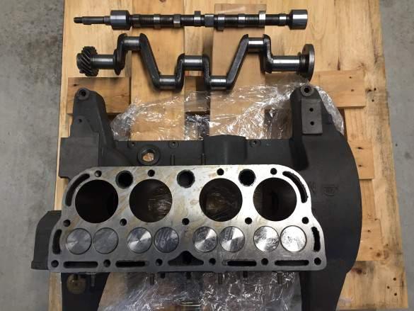
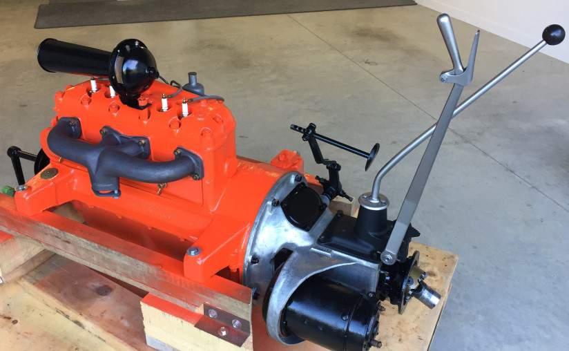
The Oxford motor has been cleaned & polished & fitted with new valves & at home prior to it’s travel to Levin for the final process
At this stage I now had several Morris mentors & found out that the oil pump was the Achilles heel of the motor & had given trouble since before the 1930’s & many owners had come up with various modifications with varying degrees of success but the motors kept wearing out. In later years an
Auckland Morris owner had come up with a revised modification based on one of the earlier ones & it was successful. Many UK cars have since been modified to this change. In short, the pump has a piston shaft driven from 4 lobes on the cam shaft, with a travel of about 2mm, 50 times a second at 750 RPM. The ball bearing hammers a pin & wears a groove in it, & the volume of oil pumped reduces. So the bearings wear out & eventually seize. I’ve studied the wear in both of my engines & concur. The oil pump lubricates the main bearings, cam shaft & splined gears, is splashed up to the cylinder walls & travels from the rear crankshaft bearing into the clutch housing to wet the clutch corks & thrust bearing. The piston conrod big end bearings have a separate lubrication method.
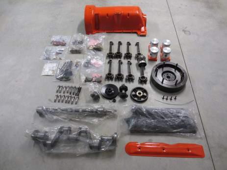
All parts cleaned, identified & bagged for the trip South
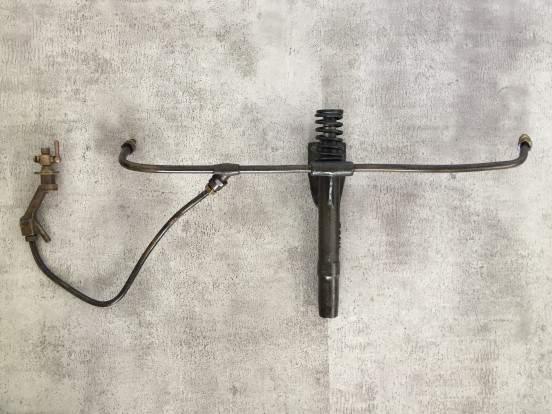
The pesky oil pump. The Achilles heel of early Morris
The Motors Trip South – early Feb 2021
I made a support frame & bolted the engine to it, so that would sit upright on the trailer & not damage the deck as we bounced along the pot holed kiwi roads.
Then I reviewed the frame height, as I was sending the sump south as well, it would need to be fitted following the restoration. So I measured the required height & bolted blocks under the frame. Then we re-wrapped the motor in plastic. I strapped the set up to the trailer & drove along Omokoroa Road to test it out. This road is under reconstruction. The trailer bounced along & the frame skewed a bit, so that was fixed & another trip was made. Then back home to put a tarp over as rain was due on the trip the next day. I left early & had a steady trip in heavy traffic & was held up with stop/go road works as expected. I arrived early afternoon.
I discussed the work required & gave the engineer the oil pump modification along with the factory bearing specifications. This included the Morris tech data sheets (including magazine articles relating to the bearing groove patterns & oil pump etc) & the photograph that I took of the big end shell beveled edge, he told me about a ‘hydrodynamic oil flow principle’. I automatically assumed that he would follow our pattern. I left for home satisfied that I finally had the job sorted.
Another Trip South – April 2021
Mid April I sent an email to Murray to find out a start date for the restoration, as he had told me that he would read my notes & check all the parts boxes, then give me a call before starting. He replied that it would take 5 or 6 weeks to finish. I was holding back a couple of gaskets to send as soon as I had heard, as I had now calculated that the job would be ready about the last week of May. 3 weeks later to my great surprise I received an invoice & was told that the job was finished. I still had the gaskets.
So I drove to Levin to pick the motor up. He had made the gaskets. My first question was ‘did he modify the pump’. He said yes, that it was a very simple procedure. Then I asked about re-metalling the big end shells & he said ‘yes but he didn’t groove the X’s’. When I queried this, he went into the explanation of the hydrodynamic principle again, & mentioned the words ‘oil pressure’ & oil wedge. He said that the oil is lost in the grooves so that there is none between the rotating surfaces. (I also seem to remember that he said that the oil is pushed out the sides) He also said, that the big end caps & conrod ends had been thrashed, & had a step worn in them & he had to do some work to reinstate the shape & make up special shims. There was so much to take in that I assumed that all was ok.
Checking Top Dead Centre
Later in the evening (at a Motel at Taihape) when I was reflecting on the discussion, I thought ‘what bloody oil pressure’ the conrods had dippers. It was too late to do any thing then, so I had a terrible night & couldn’t settle. I decided to ring him in the morning & sort it out, but after no answer (his answer phone says to ‘send an email) I decided to return to Levin. I tightened the ropes on the trailer & got back into the car & tried the ph number again. He answered. We had the discussion, & he reminded me about the principle & explained it again. He referred me to a website, & said that years ago that he had attended a Motor Restoration Conference & had learned about the principle, & had been applying it for 30 years, & that is how he does all of the Vintage Cars. He is very well regarded by the Ford people. He reassured me quite forcefully ‘not to lose any sleep that there will not be a problem’. That the ‘conrod splashes in the oil & forces it up the dipper, thereby creating the oil pressure’. I left for home, having to believe that he knew more than me. The next morning I looked up the hydrodynamic principle, & now see the oil wedge that is pushed around the crankshaft, keeping the surfaces apart. The next day I called on the Tauranga engineer who started the original work, & told him about that the job had been completed, & could he submit an account for his work. I also asked him if he knew about the principle, & did he groove bearing shells? He said ‘usually no’ but in some cases there was only a groove in the top shell, so that oil was available for start up. Now back in Tauranga, I un-loaded the motor with it’s frame onto a trolley, took photos, & pushed it into a corner of the garage.
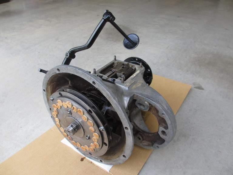
The rebuilt clutch assembly
My next project was to start restoring the body timber frame at a family workshop in Auckland. Then another Covid lockdown came & I couldn’t get back to Auckland, so I pulled the motor out of the garage corner to paint it.
Finding Top Dead Centre
Before painting the motor, I decided to put the crankshaft pulley back on & to find & mark the TDC. I unscrewed a plug in the head over piston number 4 & put a rod down to touch the top of the piston. I rotated the flywheel but there was no movement of the rod. Bugger, there must be a carbon plug in the hole. Why didn’t I check before?
So I debated what to do. I took the tappet cover off & rotated the flywheel & watched the valves go up & down & wasn’t sure that I was rotating the flywheel the right way. Silly me, I should have realized that the crank handle always rotates clockwise. So off with the head, hoping that I didn’t damage the head gasket. I watched the pistons go up & down in time with the valves. I had put a marker on the motor behind the pulley & lined it up with what looked like a scratch on the pulley, I now had TDC. I now decided to check the settings of the tappets. What a cow of a job, I needed 3 hands, each holding a 1/4'” Whitworth spanner. I found out later from a mentor, that there were a number of small tools invented by previous Morris owners, which rest on the side of the motor to hold the lifter, while the tappet is adjusted. I had earlier decided that in the future if the tappets need adjusting, when the motor is in the car, that I would have to reach over the wing (mudguard) & this could be awkward & uncomfortable. I don ’t fancy adjusting the tappets again for a long time. Now to get the head back on & to get a good seal. I had noticed that Murray had used a sealant on all of the gaskets, so I went to Supercheap Auto to buy one. After looking at many, most in a tube or can & not suitable for high temperatures, I was getting scratchy, until I came across the amazing copper adhesive in a spray can, especially for the head. So back home I suspended the gasket on 2 wire hooks (hung on a step ladder on the lawn) & after spraying both sides & waiting for about 5 minutes, I carefully carried the gasket to the garage, to be very carefully maneuvered over the studs without touching the surface & then tightened the head nuts to the specified torque.
Finding Top Dead Centre
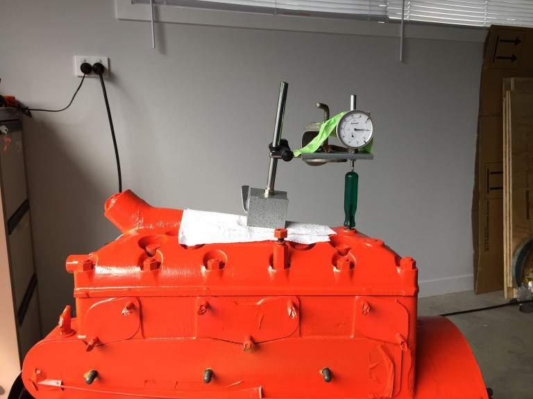
I masked the motor in various places & applied 2 coats of ceramic high temperature paint. I fitted the magneto & set the timing, & was sure that my TDC was perfect, but I thought ‘let’s make sure’. So I looked into my tool box where I had a magnetic block & dial gauge (from my early days of re -building refrigeration compressors), removed the timing plug again, inserted a screwdriver to touch the top of piston 4, jury rigged the magnetic block & gauge. When the flywheel was turned over it was perfect.
Early in the restoration period my mentor suggested that I re-cork the clutch plates. There are 2 cork lined plates separated by a plain steel plate. The splined clutch gear hub was partly worn & the corks were a bit skinny. I shopped around at home brew shops & online, before coming up with the appropriate corks. The ones that I needed had to be 'Natural' not the compressed ones, as sold by Ali Express. There are 52 holes, so I bought 60. The corks were tapered, I topped & tailed them from different sides of the plates. I had some measurements of the finished length, so cut them longer then sanded to size. I stapled 180 grit wet & dry sand paper to a board, & carefully rotated the plates by hand until I got close to the measurement, checking with calipers.
I purchased a new splined gear hub, main clutch springs, clutch separator springs & self aligning flywheel bearing (from the Morris Club UK). The springs were longer & stronger.
I re-assembled the clutch & re-fitted the gearbox/clutch assembly to the motor then fitted the dynamotor.
Murray Horn recommended that before starting it, that I tow the car in gear to turn the motor over & so get the oil pump working to lubricate the moving parts,. I now decided that as it would probably be a year until the motor would be run, that I would crank it over now & then.
I filled the oil to ¾ level, left the spark plugs out & went for it, cranking 50 times with both hands until I’d had enough. I did this again the next day & noticed something shiny coming from under the masking tape covering the valve which supplies oil pressure to the dash board gauge. It was oil.
Yoo hoo the oil pump works!
A post script to this restoration, I also purchased 4 x 18mm long reach spark plugs. The car had been driven with the wrong spark plugs for many years, so there should be a big improvement with the original factory installed Oxford motor & the fixed pesky oil pump.


