

VIJAY ENGINEERING AND MACHINERY COMPANY
Electro-mechanical Solution Provider


Electro-mechanical Solution Provider
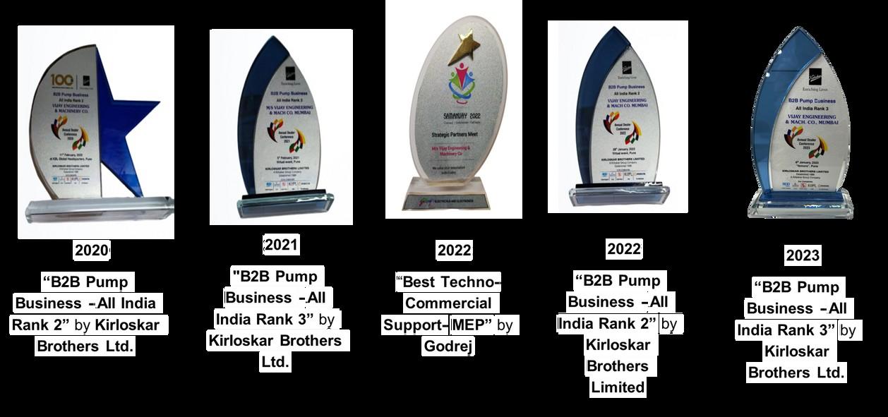
• Channel Partner with Kirloskar Brothers Limited since 1960
• Presence in Mumbai, Thane, Raigad, Navi Mumbai, and surrounding Industrial belts
Core competencies: Building and Construction Sectors
• Availability of variety of pump sets for multiple applications
• Technical understanding and application knowledge across various application domains
• State of art- Testing facility
• Strong after-market support service support team
• Ranging from energy audit to predictive maintenance and energy efficiency improvement solutions.
• VEMC

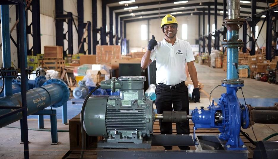



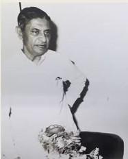

VEMC was founded by Shri. Shantikumar Shah with a vision to deliver engineering excellence.
1948




Focus on Turnkey Projects & Electricity Boards
19701980


1950 - 1960

• Associated with Kirloskar Brothers Limited
• Execution of Defence & Railway Projects

1990

Growth driven by Privatisation and Industrial sector expansion
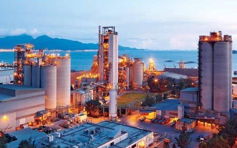








VEMC aspires and strives to be the most reliable and endearing electromechanical solution provider.





To evolve into professional organization through a systematic & phase wise growth approach that will act as a foundation of happiness for employees, customers, stakeholders and the society at large. The bi-product of this activity shall be wealth creation.








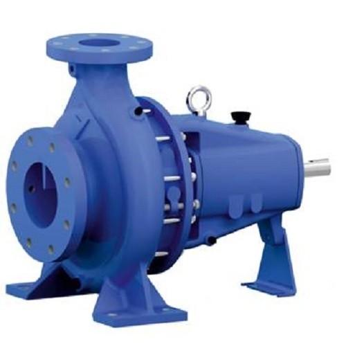
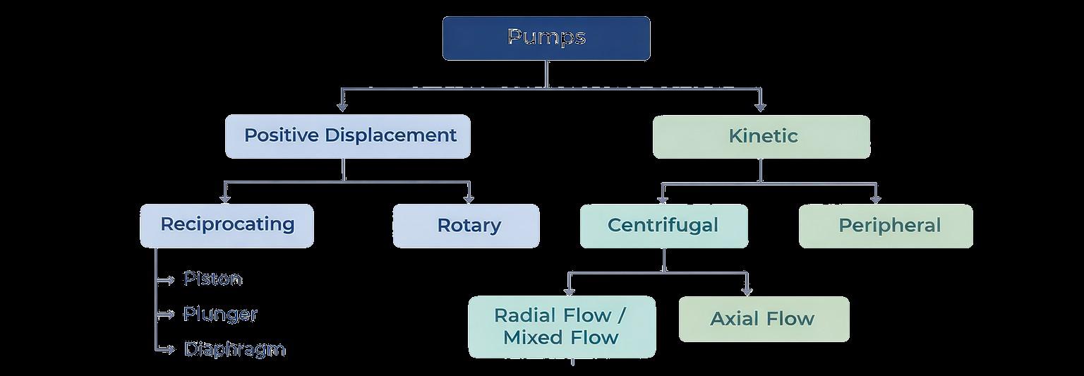
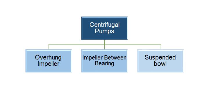
• Mass Produced, hence economical cost.
• Typically used for applications with discharge pipeline sizing below 150 mm.
• Overhung impeller design limits bearing L10 life, usually less than 25,000 Hours.
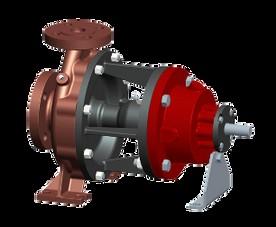
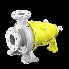
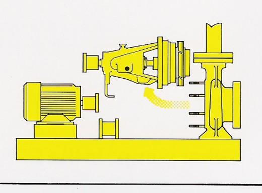
• Back-pull-out design- Helps in easing the maintenance of the pumps
• Main Hydrant / Sprinkler pump in fire (upto 3200 lpm & 145m head)
• Gland packing should be the preferred choice for ease of maintenance instead of Mech Seal
• Designed for increased life.
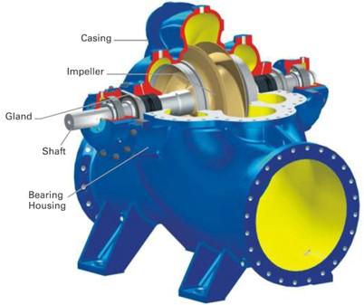
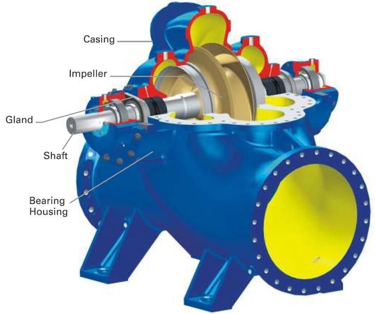
• Between bearing arrangement of Impeller
• Easy to maintain without dismantling piping
• Typically used for utility-type applications with discharge branch sizes above 100 mm.
• Suitable for fire application at 2900 rpm as well as 1450 rpm
• Main /Jockey pump for fire application.
• Horizontal as well as Vertical Orientation available
• Single outlet pumps for one zone
• Multi-outlet pumps for low-zone and high zone (5 outlets)
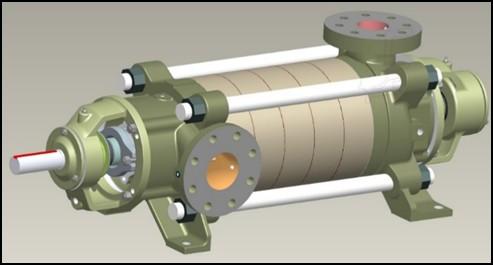
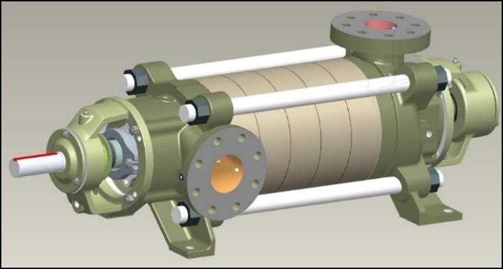
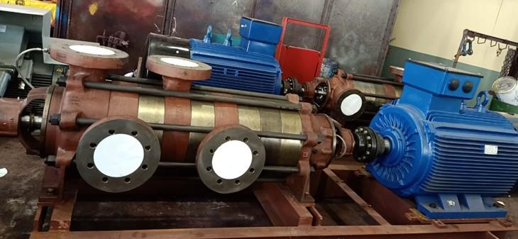
• Designed for low to medium flow at high heads.
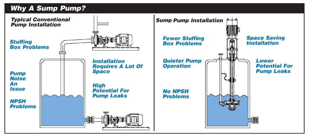
• Typically used in applications where suction lift and associated priming problems exist.
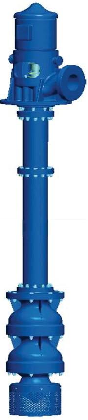
• The pump being suspended in the sump negates the requirement for a separate dry well.
• Used in Oil & Gas fire applications, jetties, and platforms.
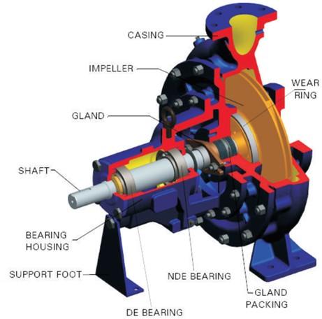
A centrifugal pump is a device which with the help of a prime mover converts Mechanical energy into Hydraulic energy.
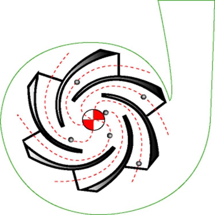
• The two main components of a centrifugal pump :Volute Casing and Impeller
• The impeller produces liquid velocity and the volute forces the liquid to discharge from the pump converting velocity to pressure.
• A centrifugal pump impeller slings the liquid out of the volute.
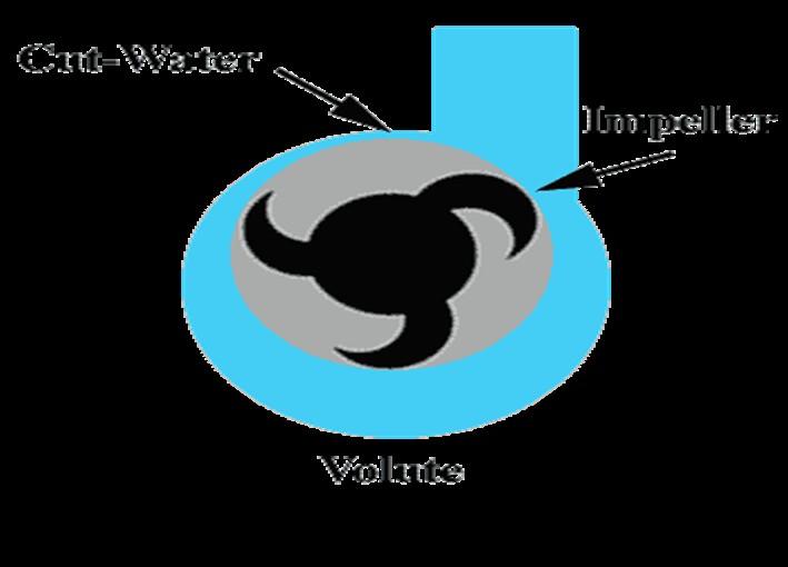
When the impeller of a centrifugal pump whose Casing & suction piping is filled with liquid to be pumped is rotated at a particular speed, the liquid inside the casing is expelled out into the delivery pipe creating a drop in pressure at the suction side of the impeller.
Then the new liquid is forced by atmospheric or other pressure into the rotating impeller.
The impeller discharges the liquid at its periphery at a higher velocity. The velocity is converted into pressure energy by means of a volute
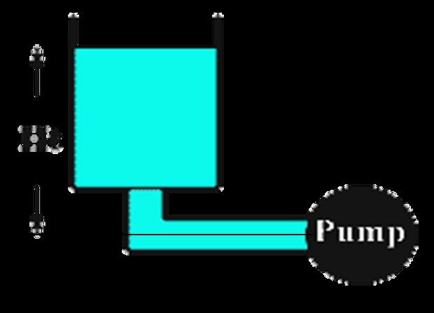
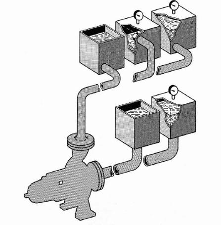
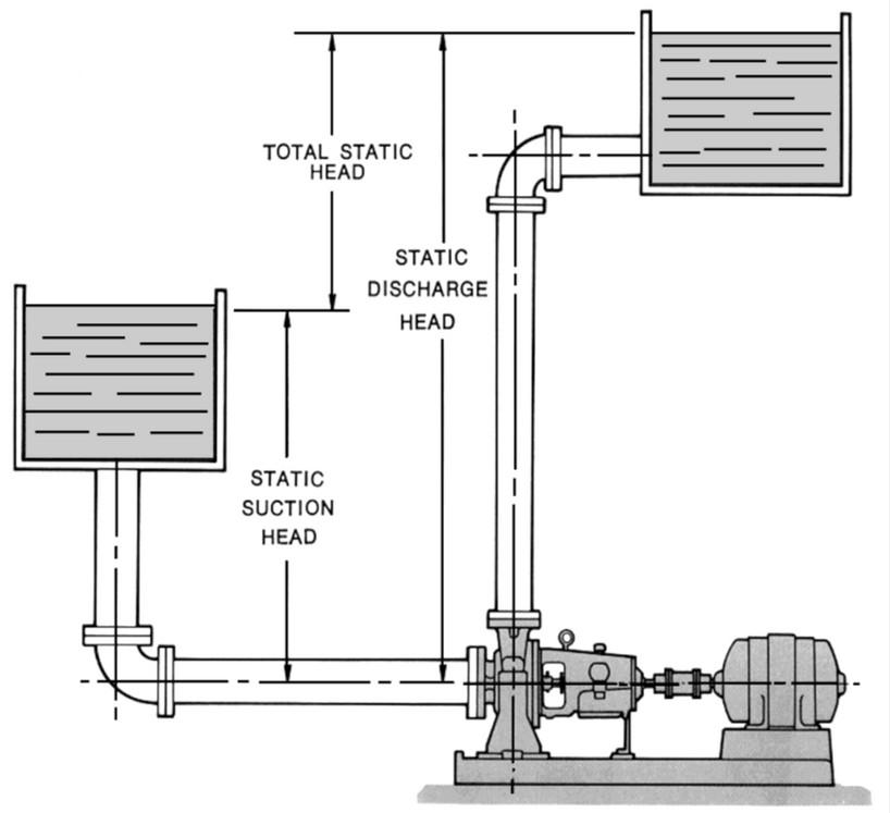
• When the liquid is taken from an open to atmosphere tank
• Where the liquid level is above the centerline of the pump suction, the static suction head is the vertical distance in meters to the free level of liquid to be pumped
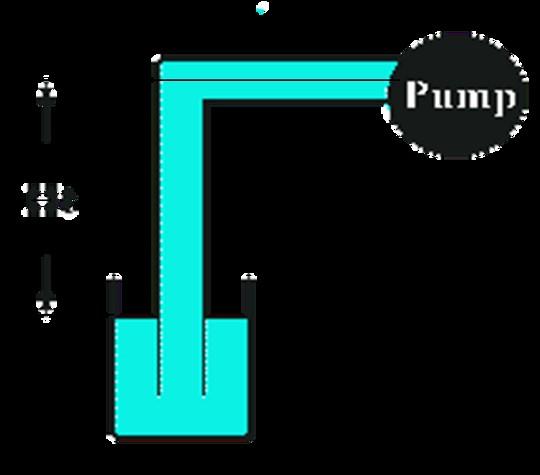
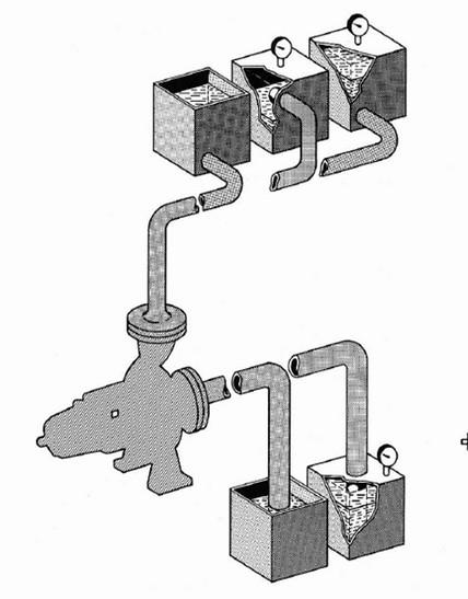
• When the liquid is taken from an open to atmosphere tank
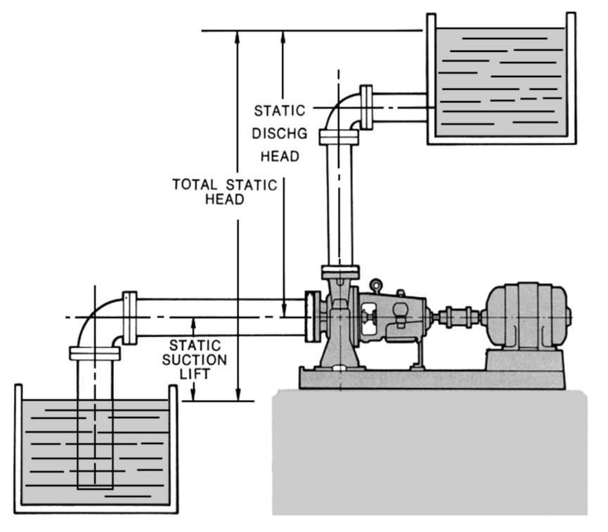
• Where the liquid level is below the centerline of the pump suction.
• Static suction head is vertical distance in meter to the free level of liquid to be pumped
• Total Static Head in Pumping system where the suction tank is located below the center line of the pump
• Total Static Head in Pumping system where the suction tank is located above the center line of the pump
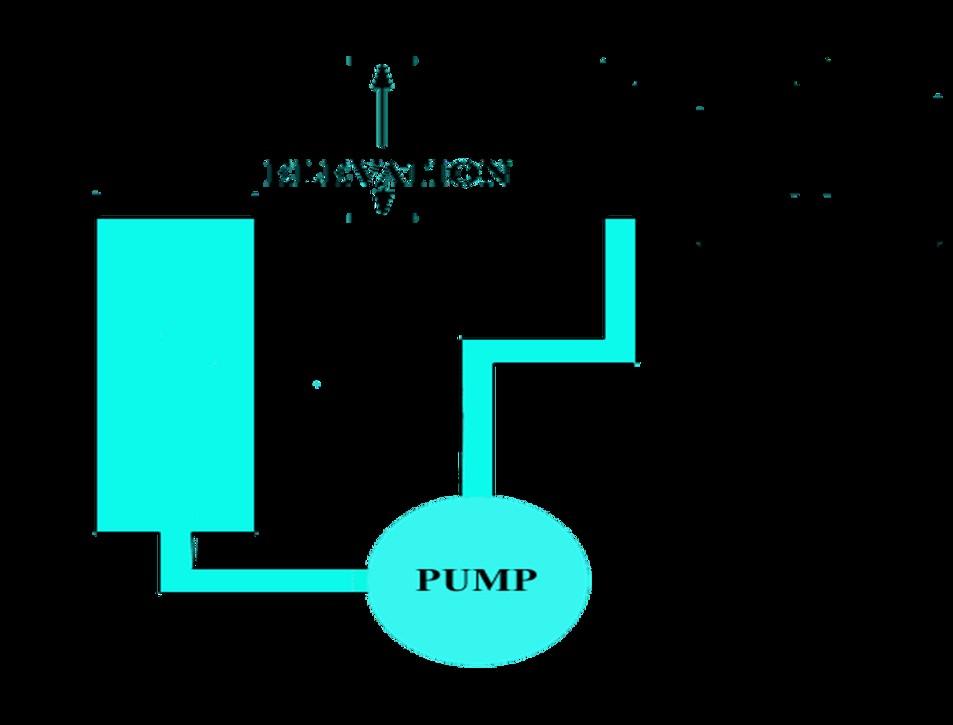
Total Differential Head (TDH) = Elevation + Friction head loss + Velocity head at Delivery
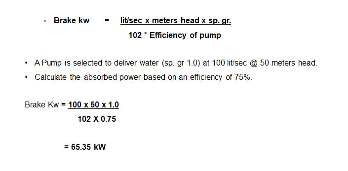
• Good engineering practice, is to allow a margin of power in hand when selecting a driver.
• As per TAC norms, the motor rating shall be more than the pump input at the shaft at 150% Q and the head not less than 65% of the rated head

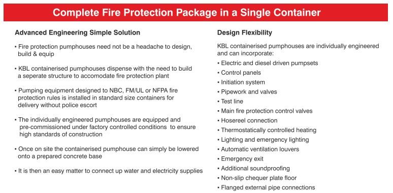
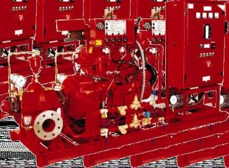
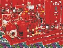
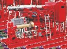
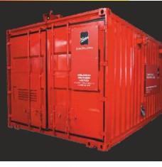
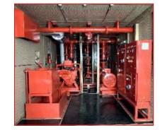
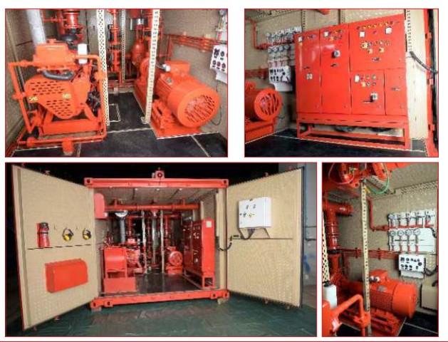
The ultimate in tailor made fire protection pump package is the KBL containerised pump room, housing pumps, control systems and pipework. After simply connecting the water and power supplies on site, the unit is immediately operational.









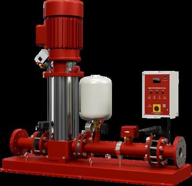
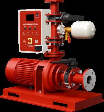
SMART SOLUTIONS FOR RESIDENTIAL AND DOMESTIC APPLICATION
Technical
Specifications: Applicatio ns:
• Flow range: 100 to 1250 lpm
• Small Shops
• Head range: 6 to 46 meters
• Operating sprinklers: upto 8 nos.
• Cost effective solution for small premises
• Plug & play packaged system delivered to site
• Clean environment at site due to minimal activity
• Digital display for monitoring of pressure and faults
• Periodic auto test facility ensures healthyness of the system
• Compact IP 55 control panel with embedded controller
• Available in Single & Three phase motors
• Single/Duplex Bungalows
• Villas • Residential Buildings
Warehouses
• A pump & driver must be in alignment to ensure satisfactory vibration free operation.
• Misalignment will result in premature rubber spider, coupling and bearing failure.
• Typically final alignment should be within 0.05mm.
• Pump & driver should be level
• Stresses in the pipelines should not be transferred to the pump
• Support all pipework and avoid loading the pump nozzles.
• Suction strainers
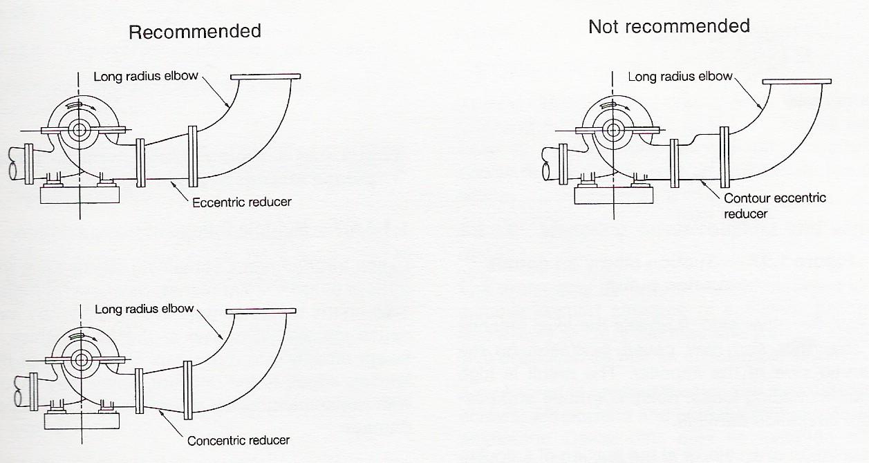
• Fit Eccentric Reducers to pump discharge connections to maintain Laminar flow into the pump casing
• The suction pipe size should be a minimum of one size higher than the suction port of the pump
• Flow velocities should be kept low under 1.5 m/sec.
• A minimum number of bends & fittings
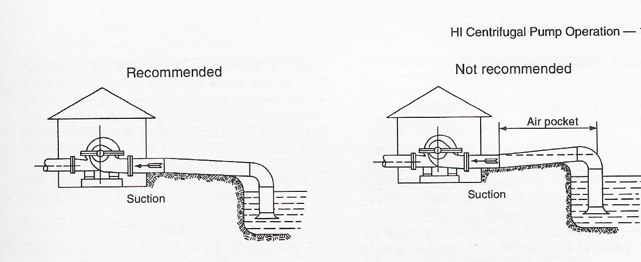
• Avoid any potential for air locking
• Keep velocities under 2.0 m/sec
• Fit Concentric Reducers to pump discharge connections.
• NRV & Isolation valves
• Support all pipework
• The discharge pipe size should be a minimum of one size higher than the Delivery port of the pump
• Fire-fighting systems are mandated in residential, commercial buildings, and industrial complexes which are highly critical in nature to safeguard against the loss of human lives and property
• Pumps have to be Fail-proof and hence critical part of the system that drives the firefighting response
• Pumps need to be operational in case a fire breaks outselection and reliability are key aspects
Scope — Covers technical requirements of centrifugal fire fighting p u m p s Intended for installation in and around building/ plants.
Corrosion Resistant Material — These are materials having resistance to corrosion equal to or better than that of copper alloy like brass and bronze having minimum copper content of 80 percent.
End Suction Pumps — A horizontal centrifugal pump with suction nozzle axis in line with p u m p shaft axis and position of nozzle opposite to the stuffing box side of t he casing. The discharge nozzle is perpendicular to the pump shaft axis.
Split Case Pump — A centrifugal pump characterized by a casing which is split parallel to the shaft and mounted in the horizontal
Vertical Turbine Pump — A vertical axis centrifugal, francis or mixed- flow type pump comprising stages which accommodate rotating impellers and stationary bowls possessing guide vanes.The pump unit is suspended by the column pipe containing a system of vertical shafting for transmitting power to the impellers,
Multistage Pump — Pumps in which the total head is developed by more than one impeller.
Maximum Pump Brake Horse Power — Is t he maximum power required by the pump at the rated speed and at any capacity within the operating range of the pump. For the purpose of this standard, operating range would be from 0 flow to 150 percent of the rated
Impeller Shafts — The impeller shafts shall be of stainless steel or material having equivalent strength, rigidity and resistance to corrosion.
Line shafts of water lubricated type pumps shall be stainless steel ( Grade 04Cr13 ofIS : 6527-1972 ) or of carbon steel with corrosion resistant shaft sleeves at bearings and at stuffing boxes.
Performance characteristic shall be of the continuously rising type.
The pump shall furnish not less than 150 percent of the rated capacity at a total head of not less than 65 percent of the total rated head.
The shut-off head developed by vertical turbine pumps shall not exceed 140 percent of the rated head.
In case of the split case, multistage and end suction type pumps, the shut-off head shall not exceed 120 percent of the rated head.
Tolerances on performance parameters shall be as specified in IS : 9137-1978 'Code for acceptance tests for centrifugal mixed flow and axial pumps—Class C'.
All pumps shall be subjected to an operation test at a speed of rotation within the limits specified in 5.8 of IS : 9137-1978.
Performance curve shall be plotted showing the efficiency brakehorse power ( kW) and total head developed at shut-off at rated capacity, at 150 percent of the rated capacity and at selected intermediate capacities between the shut-off and 150 percent of the rated capacities.
Hydrostatic Pressure Test — All the pressure containing parts, that is, pump casings and discharge casings of split case and end suction pumps, pump bowls and discharge head of vertical turbine pumps shall with stand hydrostatic pressure test for aperiod of 10 minutes without sweating and rupture. Hydrostatic test pressure shall be minimum 1.5 times the shut-off pressure or twice the rated pressure considering positive suction pressure, if any, whichever is higher.
Motor-Driven Pumps — Motor shall not be overloaded'in the entire range of operation, that is. between zero capacity to 150 percent of the rated discharge.
Diesel Engine Driven Pumps —Engines, after correction for altitude and ambient temperature, shall have bare engine horse power rating equivalent to the higher of the following two values.
a) 20 percent in excess of the maximum brake horse power required to drive the pump at its duty point, or
b) The brake horse power required to drive the pump at 150 percent of its rated discharge.
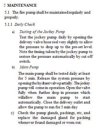
This standard lays down the requirements of installation and maintenance of fire fighting pumps.
Underground or surface water tank, constructed to store water for fire fighting purpose.
A concrete/masonry/plastic/steel tank constructed or erected on terrace of building for fire fightingpurpose.
A small tank erected inside/over the pump house and above the fire fighting pumps to keep the pump casing and suction of the fire pump permanently flooded.This is required in case of negative suction.
A valve fixed in the suction strainer of the fire pump which opens only inwards to allow in flow of water into the pump suction and fire pump when the pump is actuated automatically/manually, This is required in case of Negative suction.
In a positive (flooded) suction, a strainer placed in the suction line between the fire tank and fire pump toarrest any dirt/obstruction being fed into the pump suction.
Jockey Pump
A pump of small capacity which is set to come into operation automatically with drop in static pressure in the system and to automatically stop when the pre set pressure is reached again.
Terrace Pump
An electrically driven pump, located on the terrace connected to a terrace tank and to the internal hydrant system
Fire Pump
An electric/diesel pump installed at static water tank to charge the wet riser systems/sprinkler system,etc.
Stand-by Pump
A pump of same capacity as fire pump, driven by a diesel engine or connected to any other alternate source of electric supply.
Pump Panel
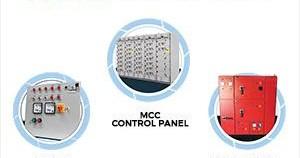
Panel comprising starting, stopping and indicating devices of fire pumps.
A switch connected on delivery line of fire pump at pre-set pressure level so designed to automatically start the fire pump or jockey pump, as the case may be, when the pressure in the system falls below the pre-set level.
The circulation relief valve put in below the shut off pressure to provide circulation and thereby relieve the extra pressure in the pump.
1.The pump house should be located preferably outside the building with a minimum clearance of 6 m from adjoining buildings
2.If the pump house has a diesel pump, the exhaust pipe of the diesel engine should be extended to outside the pump house and exhaust discharged at an appropriate height in the open air.
3.If the pump house is located inside the building,either on ground floor or in the basement, it should be separated from the rest portion with a wall having 2 hr fire rating and fire check door at its entrance having 1 hr fire rating.
4.For pump house in basement, forced mechanical ventilation should be provided. The pump house located in the basement should also have easy accessibility from outside preferably through ramp.
5.Pump house in ground floor should be located on periphery of building with access directly from outside/openarea.
1.The pump house should be of adequate dimension to house all the pumps with suction,delivery pipes, fittings and starter control panel, air vessel, etc, with adequate circulation area.
2.Adequate head room clearance all around the pump for maintenance shall be made available.
3.The pump control panel which should also be housed in the pump room but easily accessible, should be of adequate dimension
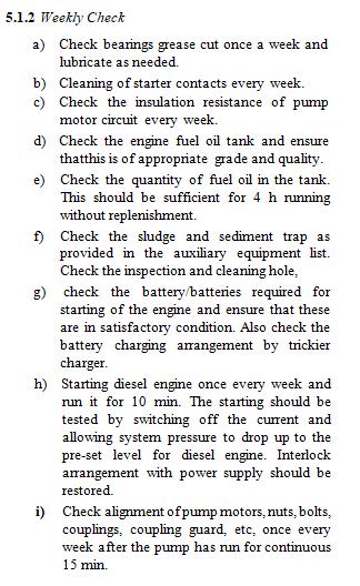
4.Where diesel pump is provided, it should have a separate panel, The panel should have its separate battery, with battery charging device, and auto-manual change over arrangement. It should incorporate an interlocking device with the main pump panel so that both the electric pump and the diesel pump do not operate simultaneously.
5.Pressure switches incorporated on the delivery line. There should be two pressure switches-one with upper and lower limit for jockey pump and another one with only for lower pressure limit for the main pump. Stopping of main pumps should be only by manual push button
6.Similar lower pressure limit switch should also be incorporated in the diesel pump to make the start automatically at pre-set drop in pressure.
1.The capacity of the fire pump should be carefully chosen to meet the maximum requirement for the risk
2.450 lpm and 900 lpm are basically the pumps to be installed on the terrace to feed the Down Comer System. The other pumps are to be housed in the pump house.
3.All pumps are required to be start on 'Auto', when there is a drop of pressure in the mains. These are required to be pre-set on predetermined pressure
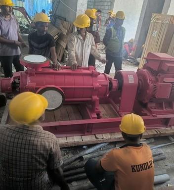
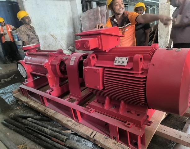
4.The pump and the motors are always connected together by couplings and they are mounted on a common baseplate
5.In the first stage of the installation, pumps are to be mounted on a concrete foundation It shall be of adequate thickness and dimension depending upon the type of the pump which will be installed.
6.It is recommended to provide a jockey pump to take care of system losses. The capacity of the jockey pump shall neither be less than 3 percent (with a minimum of 180 I/min) nor more than 10 percent of the installed pumping capacity.
7. Pumps (other than Jockey pumps) should be able to develop head of greater than 65 percentof rated head at capacity of 150 percent of rated capacity.


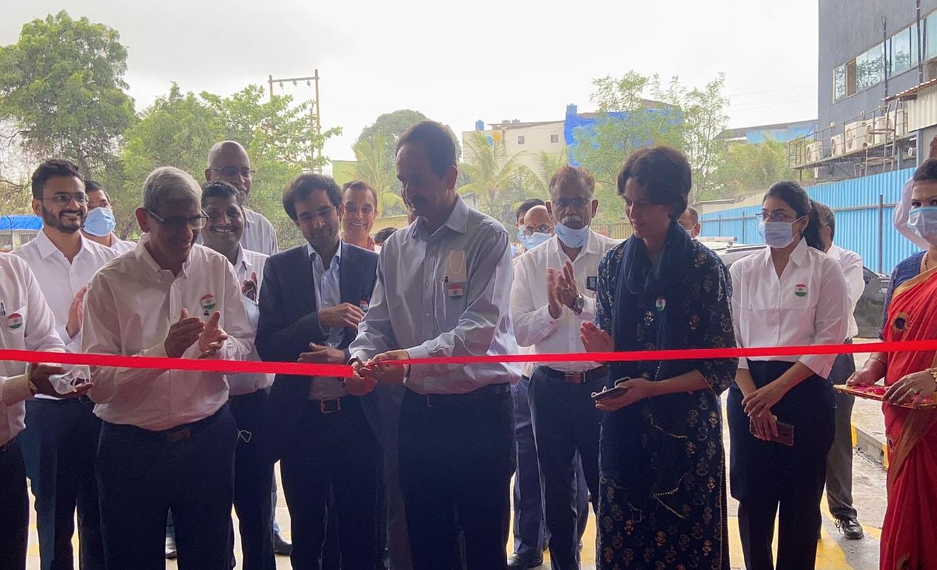
• APOEM (Authorized Pumpset Original Equipment Manufacturer) is the Pump set brand of Kirloskar Brothers Ltd (KBL) wherein the state-of-the-art pumps are engineered, manufactured & tested to develop a range of leading-edge solutions for Total Fluid Management.

• All the machineries and equipments are installed as per KBL recommendations.


Aligning with KBL’s expansion plans in future



Partner



• Trust
• Transparency
• High Reliability
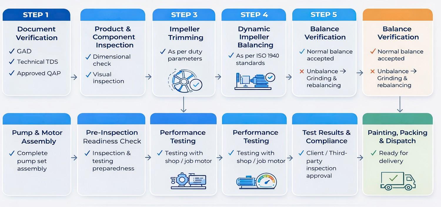
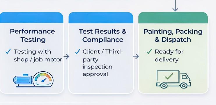
• Witness Testing
• Customised Product Range
• Quality Control
• Shorter Delivery Periods
• Customer centricity
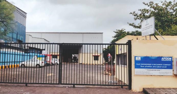
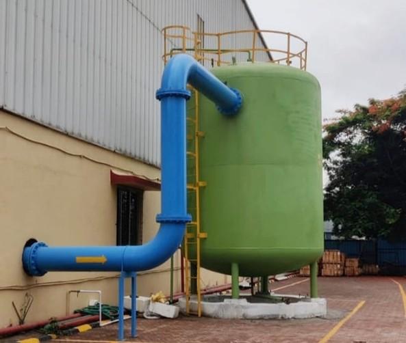
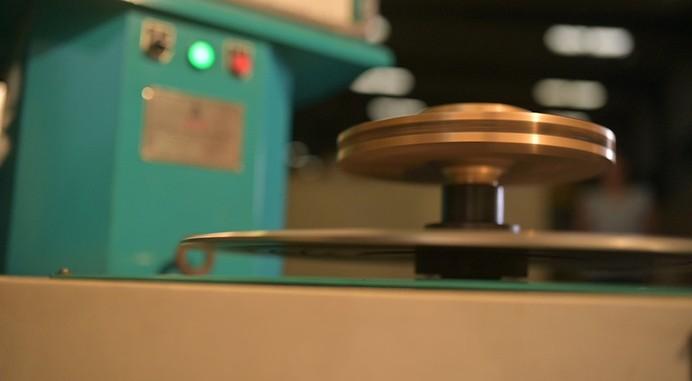
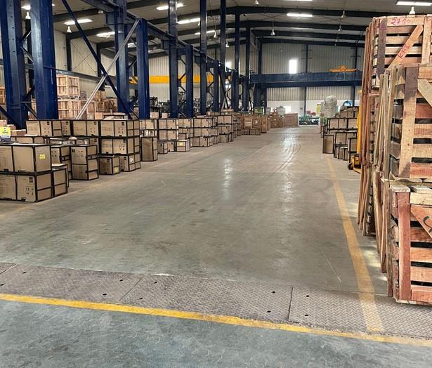
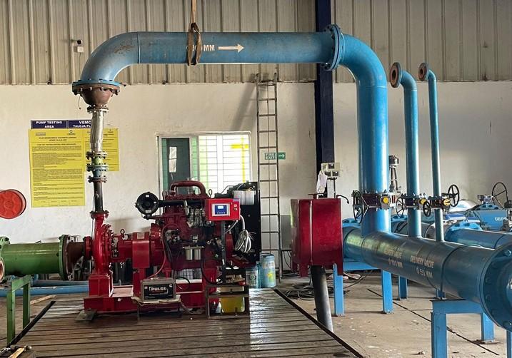

APOEM Works Unit : Survey No.109,110,behind King fisher Company, Wavanje,Taloja,Navi Mumbai,Maharashra 410208


Notes:1) Hydro test shall be carried out at 1.5 times of maximumdischargepressurefor10minutes.
2) Vibration and noise level shall be measured at dutypointonlyandacceptancevalueshallbereferredasperKBLconstructiondatasheet.
3) Pump testing shall be carried out as per KBL testingprocedure.
4) O & M manual shall be supplied along with pumpsets.
5) Refer IOM manual for bearing temperature limits.
Additional Witness at the time of inspection other thanstatedaboveshallleadtoadditionalpriceimplication.
Approved data sheet
Approved data sheet
ISO 21940/ISO 1940 Gr. 6.3
Approved data sheet & No leakage
ISO 21940/ISO 1940 Gr. 6.3
Complaince Report
Complaince Report
Test Report Balancing Complaince Certificate Complaince Report
Approved data Sheet/ ISO 9906:2018 Gr 2B, As per KBL Standard Operating Procedure PerformanceTest Report


Works Unit : Survey No.109,110,behind King fisher Company,
3) Pump testing shall be carried out as per KBL testing procedure.
Complaince Report ISO 21940/ISO 1940 Gr. 6.3
Balancing Complaince Certificate
Test Report
Complaince Report
Complaince Report P P P P
Approved data Sheet/ ISO 9906:2018 Gr 2B, As per KBL Standard Operating Procedure PerformanceTest Report
and noise level shall be measured at dutypoint onlyand acceptance value shall be referred as per KBL construction datasheet.
4) O& Mmanual shall be supplied along with pump sets. 5) Refer IOMmanual for bearing temperature limits.
6)Additional Witness at the time of inspection other than stated above shall lead to additional price implication.
7)Pumpset upto 150 HP can be inspected.

Refer note - 2 & 3 Witness one number per model Refer note - 1 Refer note - 5
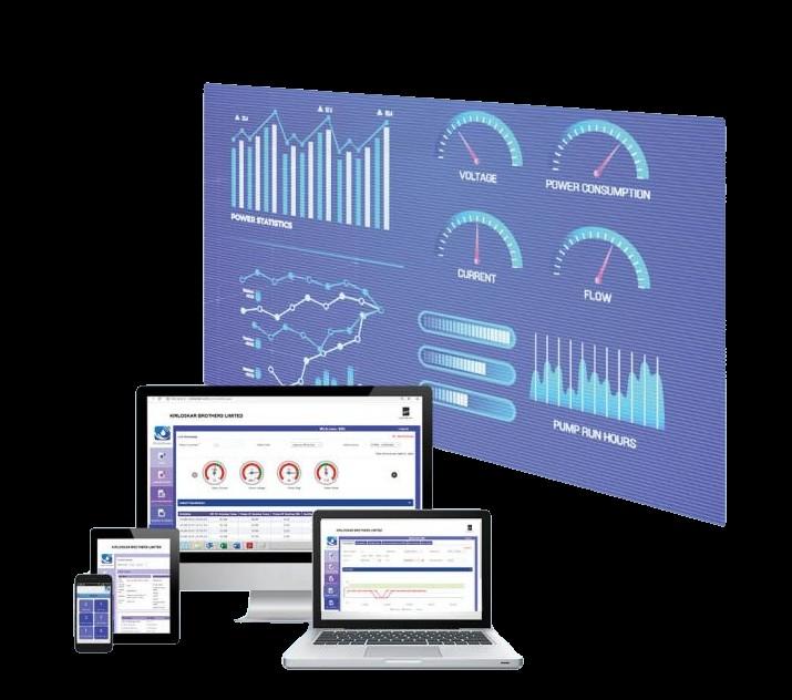
IoT-enabled system that delivers realtime data, instant alerts, and actionable insights — helping you reduce downtime, cut costs, and extend pump life.
KirloSmart™ – Monitor

Remote
Monitoring


Application
Performance

Alarms and Warnings


Predictive
Maintenance
Historical Data
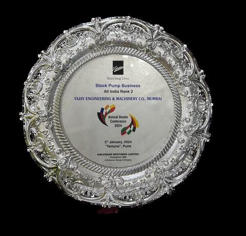
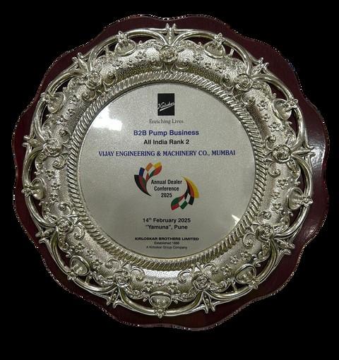
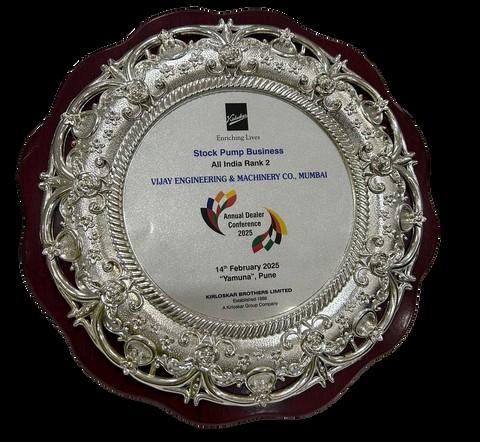





















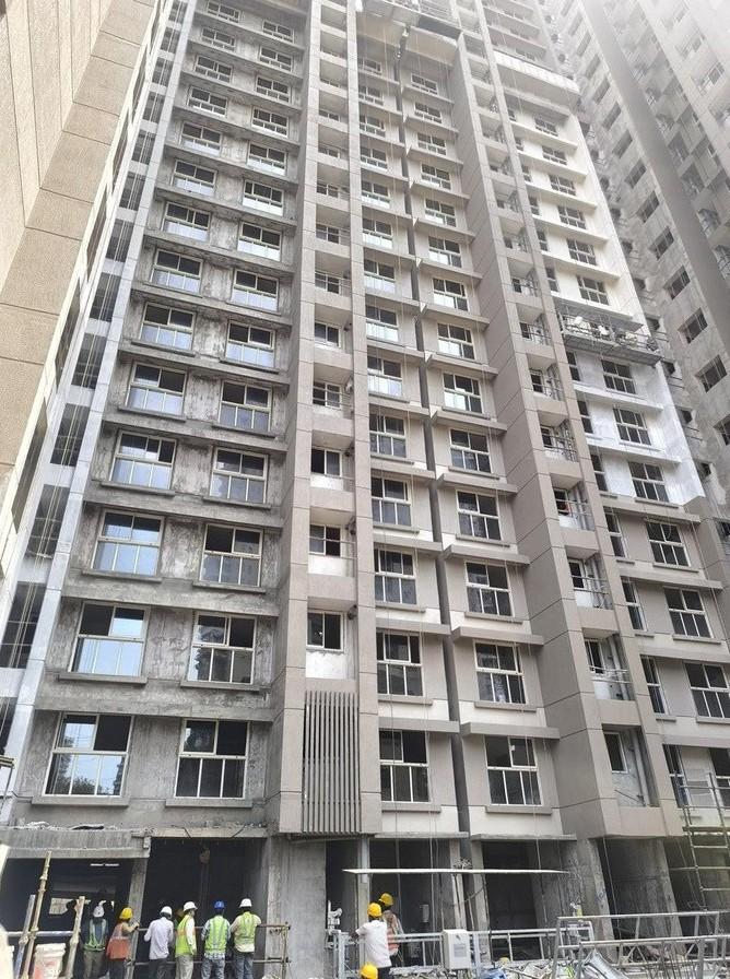
• Scope: Fire Fighting & PHE Pumps
• Order Secured: ₹2.38 Cr (Tata) + ₹1.56 Cr (Capacite)
• Challenges Addressed:
⚬ Modified BOQ to address 10 LPS @ 155m head deviation
⚬ Extensive coordination with Tata, AECOM & architects
⚬ Conducted live product demos at MHADA & BKC
• Execution: Completed delivery for 8 buildings within 2.5 months