8 minute read
Cr eati n g th e T ottor i T able LarsWust


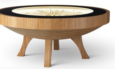
Three sum m ers ago, I was sitting with m y sister in our backyard, m indlessly watching Youtube? when we both saw a video of a com m ercially sold ?Sisyphus Table? It was m esm erizing: a circular coffee table with a bed of sand underneath a glass top. A m etal m arble would then effortlessly glide through the sand, being pulled by a m otorized m agnet underneath the table, leaving an intricate geom etric trail behind We were both captivated and just needed to get one, so we went to their website. The $2000 price tag im m ediately ended our hopes of ever getting one. But I thought: If I can? t buy one? why not build one?
Just one sm all problem ? I knew alm ost nothing about engineering, woodworking or really any skill needed to tackle such a project However, I blindly progressed forwards. I first needed wood for the table?s base, but plywood was too expensive so I went dum pster diving down m y street until I found a usable piece of wood I then watched Youtube tutorials on how to cut the wood into a circle using a table saw, and eventually how to program an Arduino to control Nem a-17 stepper m otors. Over the next few years, I went through m ultiple design iterations and eventually settled where the project is now? so let m e give you a quick rundown of how it works.
Advertisement
The inner m echanism uses two stepper m otors. One slides the m agnet back and forth on an axis using a ball screw linear actuator, and the other m otor rotates the entire axis around the center of the table. By using this approach, the m agnet can reach any point within the circle. The m echanism relies on polar coordinates, where instead of using X and Y coordinates like you would in a 3-D printer or CNC, you specify an angle and a distance from the origin, where each m otor corresponds to either value. The m otors them selves are Nem a-17 stepper m otors, which rotate in very sm all increm ents and are controlled by TM C2209 stepper m otor drivers. The stepper m otor drivers are then controlled by the ?brains?of the table, the ESP32. The ESP32 is a super inexpensive m icrocontroller akin to an Arduino, except it runs with Bluetooth Low Energy and W i-Fi built in! Using this wireless connectivity, I was able to create a m obile app using Flutter, Google?s m ulti platform app developm ent fram ework.

The app uses Bluetooth to connect the table to W i-Fi along with short actions such as pausing or playing the current design. W i-Fi is used to upload and download different track designs to and from the table with an H TTP web server. But enough with the boring technical jargon, let's talk about actually building the table.
I?ve gotten m any parts off of Am azon, and learned how to use them through online resources But som e parts of the table I had to build m yself. This is where the Innovation Lab cam e in to help m e W hen I started working on this project, I was not yet a student at Westm inster and had little to no access to proper tools and equipm ent. However, since I started m y current year, I?ve been able to utilize m any different parts of the lab. I laser cut a 345-tooth wooden gear to use for rotating the central axis I also had to 3D-print a couple parts to support the ball screw axis, house the m agnet, or m ount the rotational m otor.

One m ain goal I had in m ind while designing this project was ease of use I could have probably finished the table m any m onths earlier if I had gone with a sim pler approach by elim inating wireless features, scrapping the m obile app, and just reading files directly off of a m anually-loaded SD card. But I wanted to create som ething as close to perfect as I could so that I could be proud of it. It has been very difficult, but I?ve designed it so that even m y grandm other could use it.
Looking back three years ago at m y sister and I m arveling at the joys of art and engineering, it?s m otivating to see how far I?ve com e M y favorite part of this project has been being able to see things slowly com e together? but I?m not quite finished just yet. I still have to actually build the whole exterior of the table as I?ve only really finished the inner m echanism , program m ing, connectivity, and the m obile app. However, I have really enjoyed working on the project so far and it has given m e a m uch greater understanding and appreciation for STEM . I?m looking forward to continuing working on the table, and can? t wait to see what it will eventually becom e.

Max Scholle
FDM ax is m y custom -built 3D printer. Since Septem ber, I?ve been working to fabricate m y personalized design with m y own hands, and the experience has been as rewarding as it?s been fun Constructing FDM ax gave m e a chance to create a m achine with features com m only overlooked on the m arket, and m ore im portantly, the project taught m e invaluable lessons that proved vital to m ake it all possible
Over the two years that I owned a 3D printer, I learned plenty about how 3D printers work. I got m y first 3D printer for m y 13th birthday, and I had alm ost no idea how to operate and m aintain it by m yself. Nonetheless, I quickly learned the skills and m echanics of 3D printing, and m y 3D printer becam e one of the m ost fun and interesting things I owned. But by the tim e I turned 15, I wanted som ething better. M y Anycubic M ega S 3D printer was great, but I wanted a m achine that I could m odify, upgrade, and connect to other things, som ething that the proprietary design didn? t seem to provide. Conveniently enough, that was when I started m y tim e at Westm inster, which offered m e the resources I needed to pursue this idea

Advantages
FDM ax is m eant to im prove on all of the areas in which I noticed m y Anycubic M ega S was lacking, taking inspiration from existing products. It isn? t just Fused Deposition M odeling ? it?s Fused Deposition M ax-im ized! FDM ax offers these awesom e features to nam e a few, things that you won? t find in lots of the 3D printers on the m arket:
- Vertical bed: M any 3D printers on the m arket have beds that m ove back and forth to serve as the y-axis, but that m eans that their footprint depth is alm ost twice their bed length! FDM ax has a bed that only m oves up and down, so y-m otion m akes no contribution to the footprint.
- CoreXY design: M ost Cartesian 3D printers are built with one axis that m ust carry the m otor for another. This results in m ore work having to be done by the printer as it m oves, and therefore less speed and m ore wear W ith CoreXY, an innovative belt design allows all m otors to rem ain stationary, so the m oving parts are as lightweight as possible. (To understand the CoreXY theory, see this website that has helped m e: https://corexy com /)
- Interchangeable toolhead: 3D printers typically have a hotend, which is what m elts the filam ent and lets it flow onto the m odel However, the m otion and precision that a 3D printer offers shouldn? t be restrained to just 3D m odels; I intend for FDM ax to have plug-and-play tools in later stages, including laser engravers and even pencils, to fully take advantage of its capabilities
- Enclosure: Less-expensive 3D printers are often open-air printers, having no walls around them . H aving no walls is fine for printing in PLA (a type of plastic filam ent), but it quickly poses issues with other m aterials. W ith TPU, as I?ve observed firsthand, an open-air 3D printer releases awful fum es And with ABS, which is very sensitive to tem perature differences, the air around the m odel is too cold, causing the m odel to curl. H aving an enclosure serves to insulate the m odel and contain terrible fum es
- Integrated Raspberry Pi: W ith a Raspberry Pi, m y 3D printer would have nearly lim itless capabilities. Prim arily, it would be W iFi enabled via OctoPi, a beautiful and incredibly useful platform through which I can rem otely m onitor m y 3D printer and operate it without the need for SD cards or a connected PC Additionally, FDM ax will have a webcam , 7-inch LCD screen, and m ulticolor LED lights. Yes, FDM ax will have style!
Process
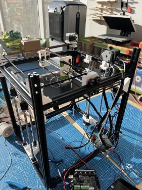
I began m ajor construction of m y new 3D printer in Septem ber (shown to the right) Originally, I intended for there to be a m eter of build length to m ake a truly m axim ized build volum e. W ith the desire to im prove as m uch as possible from m y old 3D printer, I continued work on this through the winter. Som ething was terribly wrong, though
By February, I realized that I needed to change m y approach to construction. This wasn? t new; finding what m aterials and m ethods worked best for m easuring, com bining, constructing, and realizing ideas took years of trial and error The big lesson I learned in February was that for large projects, a com prehensive design is vital for success. W hen I started construction, I knew a solid design would be necessary, but I realized in February that even a bulletproof-sounding plan can topple if it?s incom plete M y lack of foresight had caught up with m e, and com pletion becam e im possible, specifically with the belt system . That?s when I began to design m ore thoroughly in an Onshape assem bly, and I did it right All of the design fit together and included the things I wanted to include, and I just needed to build it, no questions asked. I finished m y design in M arch.

After disassem bling the partly-built 3D printer, I im m ediately began work on the fresh new concept Unfortunately, m y process was heavily delayed because the 3D printers in the lab weren? t operational, so I couldn? t m ake m y parts. Yes, it takes a 3D printer to m ake a 3D printer.
I started by creating the bed assem bly. In the picture to the left, I have the com pleted bed assem bly with the Onshape design in the background The bed assem bly had two Z-steppers and carried the bed, which slid along four rails and two screws.
After the bed assem bly, I built the fram e. The fram e m ade it start to look like a real 3D printer! After securing all of the 2020 extrusions (m etal bars) together, I put the bed assem bly into place. The m ost satisfying part of m aking things is when two separate pieces fit together perfectly. The fram e and bed are shown to the right
W ith a bit m ore work, I added three m ore stepper m otors to control the XY m otion and the extrusion. After a slight design m odification (because I didn? t want to pay $15 for longer screws), I fabricated the XY gantry, the part that carries the nozzle To com plete the m otion m echanism s, I added the CoreXY belts All of the m echanism s m oved properly.