2 minute read
Torque Output Data


Single-Acting Actuators continued
Dimension Data and Mounting Standards
Advertisement
Optional Body Air Connections
• UNI EN ISO 228 G 1/2" (sizes from 110 to 302)
• UNI EN ISO 228 G 3/4" (sizes from 253 to 302)
• UNI EN ISO 228 G 1" (sizes from 300 to 302)
Optional Bottom Flange Drilling
• ISO F04 (for sizes 52, 63, 75)
• ISO F05 (for size 110)
• ISO F07 (for size 143)
• ISO F10 and F12 (for size 190 and 210)
• ISO F12 (for size 127)
• ISO F14 (for size 253)
• ISO F12 and F16 (for size 254)
• ISO F25 (for sizes 300 and 302)
Optional Valve Shaft Interface
• Single square parallel ISO 5212
• Single square diagonal ISO 5213
• Double D
Note: standard is double square ISO 5211.
Model Number Designation
Range and Rotation
GTA = 90° rotation
GTB = 120° rotation
GTC = 180° rotation
DA = Double-acting
FC = Spring-return, fail to close (clockwise)
FO = Spring-return, fail to open (counter-clockwise)
30, 31, 32 (not applicable for double-acting)
Travel Stop
X0 = No end stop (33, 34, 43 and 44 body size only)
K0 = Single direction +/- 5 degrees
K1 = Single direction +5 to -90 degrees
W0 = Dual direction +/- 5 degrees open, +5 to -25 degrees close
W1 = Dual direction +5 to -90 degrees open, +5 to -25 degrees close
Z0 = Blocked end stop
Temperature Range
ST = Standard -50 to +70 ºC (-58 to +158 ºF)
HT = High -15 to +160 ºC (+5 to +320 ºF)
ET = Extended -60 to +200 ºC (-76 to +392 ºF)
SX = Special (consult factory)
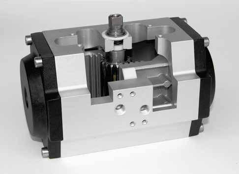
Assembly Configurations
The graphics below show the relative orientation of the piston and pinion for each configuration, as viewed from the top side of the actuator. In the descriptions that follow, that perspective is assumed. Pinion rotation is indicated for each as CW (clockwise) or CCW (counter-clockwise).
Port 2 is connected to the inboard side of the pistons. Pressurising port 2 will force the pistons out until they reach the travel stops. The direction of pinion rotation is determined by the assembly configuration. Venting is through port 4.
Port 4 is connected to the outboard side of the pistons. Pressurising port 4 will force the pistons in until they reach the travel stops (if the actuator is so equipped as they’re optional). The direction of pinion rotation is determined by the assembly configuration. Venting is through port 2. Note that on spring-return actuators, as with double-acting, pressurising port 2 will move the pistons out. When port 2 is depressurised, spring force will move the pistons in. Venting is through port 4. Port 4 is not to be pressurised on springreturn actuators.
C STANDARD OPTIONAL OPTIONAL OPTIONAL
2
PORTS
B 4
PORT 4 (OUTBOARD) PRESSURISED Shown at end of stroke PORT 2 (INBOARD) PRESSURISED Shown at end of stroke

