$16.50 inc. GST
October 2026
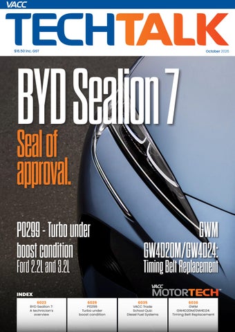
BYD Seal i o n 7 Seal of approval.
P0299 - Turbo under boost condition Ford 2.2L and 3.2L
GWM GW4D20M/GW4D24:
Timing Belt Replacement
INDEX 6023
BYD Sealion 7: A technician’s overview
6029
P0299 Turbo under boost condition
6035
VACC Trade School Quiz: Diesel Fuel Systems
6036
GWM GW4D20M/GW4D24: Timing Belt Replacement
Driven by
DOWNPOURS
Clear visibility for your safety Power Protection Plus (PPP): Makes all the difference. Choose Bosch Aerotwin Wiper Blades, the advanced Wiper Blade range from Bosch featuring an innovative adapter system and patented coating. The Aerotwin Wiper Blade range with PPP rubber provides perfect wiper performance, long service life and gentle wiper action.
boschaftermarket.com.au
1300 130 116 AUS 0800 024 192 NZ TechTalk is published by: Victorian Automotive Chamber of Commerce - Technical Services. VACC House 650 Victoria Street, North Melbourne VIC 3051 ABN: 63 009 478 209 03 9829 1111 | vacc.com.au TechTalk Technical Editor Rodney Lofts 03 9829 1292 | techtalk@vacc.com.au Technical Contributors Matthew Tan, Michael Massey, Michael Wakefield, Salvatore Cilmi and the feedback of VACC members and MotorTech subscribers.
6022
Disclaimer This publication is distributed with the understanding that the authors, editors and publishers are not responsible for the results of any actions or works of whatsoever kind based on the information contained in this publication, nor for any errors or omissions contained herein. The publishers, authors and editors expressly disclaim all and any liability to any person whomsoever whether a purchaser of this publication or not in respect of anything and of the consequences of anything done or omitted to be done by any such person in reliance, whether whole or partial upon the whole or any part of the contents of this publication.
Information on products and services contained in this magazine is published as a service. It does not imply the endorsement of any product or service by the Chamber. Copyright Tech Talk is copyright and no part may be reproduced without the written permission of VACC. Subscriptions VACC adheres to its obligations under National Privacy Principles legislation. Advertising Advertising accepted for publication in Tech Talk is subject to the conditions set out in the Tech Talk rate card, and the rules applicable to advertising.
OCT 2026
BYD Sealion 7: Seals the deal 2025-Onward BYD Sealion 7 In mid-2026, the Australian new car market reached a turning point as sales of traditional internal combustion engine (ICE) cars dropped to around 50.8%. Meanwhile, battery electric vehicles (BEVs), plug-in hybrids (PHEVs), and hybrids surged, capturing nearly half (49.2%) of all new vehicle sales (VFACTS). One of the EVs that has made a big impact is the BYD Sealion 7, which has earned a reputation as a great-value car with features that make the transition to an EV easier for new buyers. However, there are pros and cons from a service perspective. DIAGRAM 1
The BYD Sealion 7 is a batteryelectric mid-size crossover SUV that was first launched in China in 2024. The Tesla Model Y was its main benchmark, and the vehicle appears to borrow several Tesla-inspired design choices. The export-market Sealion 7 uses the older e-Platform 3.0 with a 400V electrical system. This platform incorporates BYD’s Blade batteries into the chassis, making them a structural part that not only maximises space but also doubles the vehicle’s stiffness, greatly boosting its collision resistance. However, the battery
pack can still be removed from the vehicle if needed. See Diagram 1
The Blade Battery BYD’s Blade Battery was publicly announced in 2020, and in 2021 BYD’s CEO Wang Chuanfu stated that they aimed to “erase the word ‘spontaneous combustion’ from the dictionary of new energy vehicles.” To achieve this, they have used a lithium iron phosphate or LFP battery, because of its low cost, high safety, low toxicity, long cycle life, and other advantages. Although this chemistry has a lower energy density, BYD’s packaging of cells into long, thin modules (or
BYD Sealion 7 e-Platform 3.0 Front Drive Motor
OCT 2026
BYD Blade Battery Pack
Rear Drive Motor
6023
DIAGRAM 2
Electric retracting door handle
Retracting door handles are used to improve looks and aerodynamics but could be on the way out as a design feature due to safety concerns in post-accident situations.
blades) increases the battery pack’s space utilisation when compared to most conventional lithium block batteries. These batteries have a much lower risk of catching fire and appear safe even when punctured.
Thermal management The Sealion 7 uses an advanced, highly integrated 16-in-1 thermal management system that acts like an intelligent central energy router. Instead of treating cabin climate control and powertrain cooling as separate systems, it merges them. When you need cabin heat in cold weather, the system activates an electric compressor and uses a plate heat exchanger to actively harvest “free” waste thermal energy from the car’s electric drive motors, powertrain electronics, and the battery pack itself. This significantly increases its low-temperature driving range and protects long-term battery health. DIAGRAM 3
However, this heat pump system may take a minute or two to compress refrigerant and cycle warm air into the cabin. So an auxiliary PTC (Positive Temperature Coefficient) heater is fitted which is a specialised electric resistance heater used in many electric vehicles as they get red hot almost instantly. PTC heaters use a ceramic material whose resistance rises as it gets hotter, which throttles the current flow. Pairing the heat pump with PTC heating gives instant cabin warmth while preserving battery efficiency.
Performance and specification In Australia, the Sealion 7 was released in February 2025 in two variants: Premium RWD and Performance AWD. They both share the same 82.56 kWh Blade battery; they differ in price, range, and performance figures. At launch the Premium RWD costs $54,990 and
features a single 230 kW/380 Nm rear motor, 0–100 km/h in 6.7s, and a range of approximately 480 km. While the Performance AWD costs $63,990 at launch, adding a front motor unit for a combined output of 390 kW/690 Nm, 0–100 km/h in 4.5s, and approximately 450 km of range.
Electric door handles
Like many other modern cars, the Sealion 7 uses electric pop-out door handles to improve aerodynamic efficiency, reduce wind noise, and create a sleek, futuristic exterior look. However, this trend could be coming to an end, as concerns arise that if the vehicle is in an accident, the handles may not work, hampering rescue efforts. See Diagram 2 China is introducing a worldfirst ban on fully hidden, purely electronic retractable car door handles, scheduled to take effect on 1 January 2027.
Front dual ball joint suspension
Like many other performance vehicles the BYD Sealion 7 uses a dual ball joint suspension system. This layout is also used in BMW, Audi, Mercedes Benz, Lexus and Tesla vehicles.
6024
OCT 2026
DIAGRAM 4
Front underside service points
The new rules require that all passenger doors have a physical, mechanical link that allows them to be opened from both the inside and the outside. The door must open even if the car completely loses battery power. Many other countries are considering adopting similar regulations.
Front drive motor identification number
Filler plug
Transmission filter
Drain plug
Transmission filter lock bolt
DIAGRAM 5
Centre console layout
What is it like to drive? The vehicle we had was the Performance AWD, and it was fun. Once sports mode was selected, acceleration was seamless through the single-speed directdrive transmissions attached to the motors. The traction control software was up to the task with no wheel spin. To match this type of performance with an ICE vehicle, you might have to spend well over $100,000 on a European performance model. OCT 2026
Unlike Tesla’s minimalist approach, BYD kept physical buttons and a gear selector where most drivers expect it. This makes the vehicle more familiar to drivers who may not have driven an EV before. You don’t have to read the manual or learn how to get it going.
6025
DIAGRAM 6
Under bonnet service points To access these service points, you will need to unclip and remove the panel below the wipers.
Brake fluid
AC Service points
Firstresponder loop
Coolant Fuse box Washer bottle
VIN Location
Jump start point
To access these service points, you will need to unclip and remove this panel to the left of the frunk
The front suspension system uses a dual lower ball joint layout (often called a double-pivot or virtual-axis suspension). By splitting the lower arm into two pieces, the point where the front wheel pivots changes as you steer. This creates a “virtual” steering line that sits further outward, right in the centre of the tyre’s contact patch. See Diagram 3 This is a common suspension design for premium, heavy, or high-performance EVs, as it helps counteract the immense weight of floor-mounted battery packs, keeping the steering light and responsive. This is where ICE models still have an advantage in the corners, as the Sealion is approximately 2.3 tonnes, and you can feel the weight upsetting the suspension when pushed. The rear suspension is a sophisticated 5-link design that assists road holding. 6026
The interior is well laid out, with all the luxury features now expected. One nice feature was the gear selector in the centre console. It is only a short, stubby paddle, but it is big enough to use and feel confident to do a three-point turn without needing to look at the selector. See Diagram 5
On the hoist Once we raise the car on a hoist and remove the few aerodynamic covers, the service points are easy to identify and access. The drive motors have drain and refill plugs for the transmission oil. Both motors also have a cartridge oil filter, which is screwed on and secured with a bolt. There were no obvious components that appeared vulnerable to damage, and all welds and castings looked good. See Diagrams 4 and 7
Under the bonnet
There is a large storage area under the bonnet, which is handy for the owner and is very reminiscent of the Tesla frunk. This is an excellent example of packaging components to make use of this extra space, as many other EVs have no, or very little, storage under the bonnet. However, apart from the lid for the washer bottle, all other service points are under the various covers. Removing the covers to access the service points was a trial, as many clips are hard to remove without damaging them. To access the brake fluid, remove the cover below the wipers. Accessing the AC service ports, fuse box, and other service points requires removal of the panel to the left of the frunk. There are no service points on the other side. See Diagram 6 OCT 2026
DIAGRAM 7
Rear service points
Filler plug
Drain plug Rear drive motor identification number
5-link rear suspension
Transmission filter Transmission filter lock bolt
DIAGRAM 8
Battery pack diagnostic information
You will need to select the Chinese market name HaiShi 07 EV to read the battery data on the Sealion 7.
The battery management system conveniently gives you SOC and SOH readings, which are handy. For more details, you will have to scroll through the data pages to check the battery condition.
OCT 2026
6027
DIAGRAM 9
Service specifications for the BYD Sealion 7
Fluid specifications
Wheel alignment
Coolant Specification
Ethylene glycol
Front Toe Total
0.2° ± 0.16°
Coolant Capacity RWD
6.05L
Front Toe Individual
0.1° ± 0.08°
Coolant Capacity AWD
6.65L
Front Camber
-0.5° ± 0.75°
Front Drive Motor Oil Specification
Castrol BOT 383
Front Drive Oil Motor Capacity
1.6L ± 0.05L
Front Caster
6.09° ± 0.75°
Rear Drive Oil Motor Specification
Castrol BOT 383
KPI
8.33° ± 0.75°
Rear Drive Oil Motor Capacity
1.55L ± 0.05L
Rear Toe Total
0.24° ± 0.16°
Refrigerant Type
R-1234yf
Rear Toe Individual
0.12° ± 0.08°
Refrigerant Capacity
1700 ± 10g
Rear Camber
-1.00° ± 0.5°
A/C Oil Type
POE
Front Toe Lock Nut
70 Nm
A/C Oil Capacity
470 ml
Rear Toe Eccentric Bolts / Nuts
140 Nm
Brake Fluid
DOT 4
Driveshaft Nuts
300 Nm
Wheel Nuts
130 Nm
Torque specification
Brake specification
Front Drive Motor Filler Plug
37 Nm
Front Drive Motor Drain Plug
50 Nm
Front Rotor Min. Thickness (fixed caliper)
Front Drive Motor Oil Filter
24 Nm
Front Rotor Min. Thickness (floating caliper) 26 mm
Front Drive Motor Oil Filter Lock Bolt
6 Nm
Rear Rotor Min. Thickness
18 mm
Rear Drive Oil Motor Filler Plug
37 Nm
Front Caliper Bolt
190 Nm
Rear Drive Oil Motor Drain Plug
50 Nm
Rear Caliper Bolt
30 Nm
Jump starting
For guidance to interpret this information, see the following articles.
As with most other EVs, there is a 12-volt battery to power the vehicle’s control systems and accessories. It is mounted under the passenger front seat and requires the seat to be removed to access it. Conveniently, there are jump starting points under the bonnet in the fuse box if the 12-volt battery fails or goes flat. See Diagram 6
Diagnostic Tool Connection The OBDII connector is easy to find under the driver’s dashboard, and the Our Auto Diagnostic tool communicated with it easily. However, we had to select the Chinese market name for the vehicle: HaiShi 07 EV. In the tool, navigate to the Battery Detection function to view battery data. See Diagram 8
Feedback
techtalk@vacc.com.au 03 9829 1292
6028
Lithium-ION batteries: What you need to know TechTalk Sept 2026, page 6009 How to test Li-ION Battery in an EV or PHEV TechTalk Sept 2026, page 6015
Conclusion Automotive journalists mostly agree that the cheaper Premium RWD variant is the smarter buy. It delivers more real-world range and a softer and more comfortable ride while still providing ample daily performance. But the Performance AWD is still good fun.
30 mm
Unlike other new EVs, BYD kept physical buttons and a gear selector where most drivers expect it to be, so there is not big learning curve to adapt to the car. It is a comfortable car that is hard to beat on value and features. From a service perspective, apart from the difficult-to-remove covers under the bonnet, there is nothing overly tricky to deal with for maintenance and repair tasks. And with the way sales figures are trending, there will be a lot of these and similar EVs on the road soon. For more information on how to access repair and service information on vehicles with HV systems, log onto VACC MotorTech or call VACC’s TechAdvisory Service.
Thank you to Chris and the team at Smarter Choice Auto in North Melbourne for their assistance with this article.
smarterchoiceauto.com.au 03 9828 4237 OCT 2026
P0299-Turbo under boost condition: Ford 2.2L/3.2L DIAGRAM 1
Genuine, aftermarket and cheap online turbochargers can all look similar, but there are calibration differences that can cause you trouble if you are not careful.
2011-2022 Ford Ranger / Everest • 2011-2020 Mazda BT-50 The Ford Ranger and Everest as well as the Mazda BT-50 have used variants of the 2.2L and 3.2L Puma engines over the years. These engines use similar but not the same turbos across the range, and they are not all interchangeable, which has got some people into trouble, especially if they are buying a cheap replacement from a questionable online source. We will tell the story of a couple of our VACC MotorTech subscribers’ issues with a P0299 code that they had some fun with to find the root cause of the lack of boost. The lesson is, don’t replace the turbo before you find the root cause. Turbochargers are very mechanically simple; however, the engines and electronic control systems associated with them are where the fun begins. The 2.2L and 3.2L Puma have been used from 2011 to 2022 in various DIAGRAM 2
Ford models, and until 2020 in the Mazda BT-50. “Puma” is commonly used in the trade for this engine family, although Ford marketing documentation more often describes them as Duratorq TDCi engines. They have all used variable-geometry turbochargers (VGTs), which use electronically controlled actuators to adjust boost. See Diagrams 1, 2 and 6 For more information on VGT operation, common faults and diagnostic tips, see the following articles:
Variable Geometry Turbochargers: Operation and Common Faults TechTalk March 2018, page 4475 Boost System Performance: Common Faults and Diagnostic Steps TechTalk Dec 2022, page 5325
Turbocharger Boost Control Diagnostic Tips: P2563 TechTalk Jan/Feb 2026, page 5867
P0299 – Turbo under boost condition DTC P0299 means the powertrain control module (PCM) has detected that the actual boost pressure is lower than the commanded boost pressure under conditions where boost should be produced. This is a relatively common fault code across turbocharged vehicles from many manufacturers. This code can be triggered in various ways. In the system used in Puma engines with VGTs, a combination of sensors and inputs allows the PCM to determine the requested or desired boost pressure at that moment and send a signal to the turbo actuator to produce that amount of boost. The PCM will then monitor a wide range of sensor inputs to check that the desired boost has been achieved, which is the actual boost pressure.
Vanes in the VGT This type of turbocharger controls boost by altering the vanes’ positions; in this case, it is actuated electronically. These vanes should move smoothly through their full range, but mechanical damage or carbon buildup can prevent this, which could trigger P0299.
OCT 2026
6029
Some important sensors include the BARO sensor, which measures barometric or atmospheric pressure in the outside air, which can change with the weather and altitude if you have driven into the mountains. This sensor is intergrated into the PCM. Then there is the MAP (Manifold Absolute Pressure) sensor, which measures the changing pressures inside the intake manifold. When the engine is off, these two sensors should read the same pressure. When the engine starts and produces boost, the MAP sensor pressure signal should change with engine speed and load. See Diagram 4 There is also a position sensor inside the turbo actuator that reports the current turbo vane position to the PCM, which should change with the desired boost. The MAF (Mass Air Flow) sensor signals should also change in line with engine speed, load, and boost. These signals, along with many others, form a closed-loop system in which the PCM compares sensor inputs. If any one of these signals is out of range or doesn’t match what the PCM expects, fault codes could be triggered. There are many electrical and mechanical reasons these signals are out of range. DIAGRAM 3
The following diagnostic steps are based on Ford OE testing for P0299, which appears to be common across engine types, with industry feedback included.
5.
Check the gaskets and seals between the MAF sensor and manifold for damage.
6.
Check the operation of the PCV (positive crankcase ventilation) system, the oil filler cap seal, and the dipstick O-ring, and ensure they all seal correctly.
7.
Check for leaks or restrictions in the Charge Air Cooler (CAC), which Ford calls its intercooler.
8.
Look for any obvious loose clamps, split hoses or other possible intake leaks.
9.
Raise the vehicle and check the exhaust system for any modifications or damage that might increase or decrease exhaust flow and repair as required.
MAP and BARO codes first With a compatible diagnostic tool, scan the vehicle and repair any BARO or MAP DTCs before continuing. MAP code P0069 could be a simple fix, as the sensors are known to become clogged with carbon buildup, and some MAF cleaner could improve the signals. It is still recommended to replace the sensor if this is the case for a reliable repair. See Diagram 4
Visual inspection Visually inspect the following: 1.
Inspect the vehicle for aftermarket accessories, such as air filters, exhaust systems, intake systems, performance chips, turbochargers, or other performance upgrades or modifications that could be outside the OE specifications. Repair or return to standard specifications as required.
2.
Check for modifications to the engine control software and remap as required.
3.
Look for restrictions to air flow.
4.
Check for water in the intake system.
10. Check for any exhaust leaks from the manifold to the tailpipe and repair as required. 11.
Check the wiring to the turbo to the PCM and check for any issues. There is a known common issue with the wiring rubbing through on the timing cover. See the following article for more details:
Common Fault Ranger and BT-50 2.2L 3.2L: P2563 TechTalk Jan/Feb 2026, page 5873 Test-drive after any repairs and recheck for any codes. If the code persists, continue with the following tests.
A smoke machine is your best friend There are many types of automotive smoke machines available on the market, and it is recommended to get one that can apply high-pressure to the system, as some boost leaks will only show up under pressure. They save hours of guesswork and diagnostic time.
6030
OCT 2026
DIAGRAM 4
Common causes of low boost
The MAP sensor is mounted on the intake manifold near the throttle body, and it can get blocked with carbon buildup that could trigger a low boost code.
The intercooler is mounted in front of the radiator, and original units can split or blow the seals out of the end tanks.
Smoke test of the intake system The automotive diagnostic smoke machine has had a major impact on modern vehicle diagnosis, primarily by enabling technicians to quickly and easily locate small intake and exhaust leaks that would have taken much longer to find in the past. The following OE base diagnostic steps recommend using a smoke machine, which is now an essential tool in a modern workshop. See Diagram 3 WARNING: Pressures above 241 kPa can damage engine management components. Ensure the workshop air supply is set to 137.9 kPa before connecting it to the engine. 1.
Remove the air filter element, place it in a plastic shopping bag, and refit it into the housing.
2.
The OE recommendation is the Rotunda Smoke Machine, Fuel Evaporative OCT 2026
Split intercooler hoses are a common problem on many turbocharged vehicles. You will need to check both of them. Use a mirror to check the undersides. Make sure you give them a squeeze while the high-pressure smoke is on, which could help show a split.
Emission System Tester 21800001 (522), but reputable aftermarket machines that can produce the required pressure will be fine. 3.
Remove the crankcase ventilation hose and connect the hose from the smoke machine to the intake. NOTE: Many in the trade would connect to the intake by removing the hose from the air cleaner assembly. Use your professional judgment.
4.
Fill the intake system with smoke and pressurise to 137 Kpa.
5.
Check for leaks or restrictions. Repair as required.
6.
Common areas for leaks are the upper and lower intercooler hoses (give them a squeeze while under pressure to see if any leaks show up). The intercoolers have been known to split and leak, as well as develop cracks in the plastic manifolds and various sensor seals. See Diagram 4
Smoke test of the exhaust system 1.
Ensure the ignition is off.
2.
With an appropriate method, plug the exhaust tailpipe.
3.
Connect a smoke machine to the exhaust.
4.
Fill the exhaust system with smoke and pressurise to 137 kPa.
5.
Check for leaks or restrictions and repair as required.
Check for input sensor bias 1.
Connect a compatible diagnostic tool, with the engine off and ignition on, and access the PCM to monitor live data from the BARO and MAP sensors. The MAP should be within 5 kPa of the BARO.
2.
If it is, move on to check the turbos.
3.
If not, check the MAP sensor and repair or replace as required.
4.
If the MAP is ok, check the BARO sensor, clear the PCM DTCs and repeat the self-test. If it is still out of range, install a new PCM. 6031
Turbocharger actuator operation 1.
Connect a compatible diagnostic tool.
2.
With the ignition on and the engine running, monitor the MAP live data PID.
3.
Command the EGRTP CMD PID (which stands for Exhaust Gas Recirculation Throttle Position Commanded) fully closed.
4.
Command the RPMDSD (which Ford uses to describe Desired Engine Speed RPM) PID to 1500 RPM.
5.
Command the VNT CMD PID fully open and fully closed.
6.
The MAP PID reading should increase and decrease as the VNT CMD PID is open and closed.
7.
If not, check the turbocharger compressor wheel to ensure it spins freely, without making any abnormal noises. Visually inspect the vanes on the compressor
DIAGRAM 5
wheel for damage and check the housing for debris. Repair or replace as required. See Diagram 5 8.
9.
Next, repeat the command VNT CMD PID, fully open and fully closed, while watching the actuator arm; it should move through its full range. If not, and if you can unclip the linkage from the actuator to the turbo, conduct the test again to see if the range improves.
If it does, it could indicate a problem with the VGT vanes inside the turbine housing. You should be able to move the linkage freely through its full range by hand, which would indicate that the vanes are ok.
10. If not, it is not uncommon for the vanes to seize from excess carbon buildup. Repair or replace as required. See Diagrams 2 and 6 11.
If the range doesn’t improve with the linkage disconnected, there could be an issue with
the turbo VGT actuator. Repair or replace as required.
VGT turbocharger boost pressure test If all of the above tests are ok or you have found issues and repaired them, check the boost pressure with the following steps. 1.
Start the engine and allow it to reach operating temperature, then idle.
2.
Connect a compatible diagnostic tool. Access the PCM and monitor the BARO and MAP sensor PIDs.
3.
Via the TPS CMD PID, decrease its value to 5%.
4.
Via the RPMDSD PID, increase the engine speed to 1500 RPM.
5.
Via the VNT CMD PID, command it to fully open, then record the MAP PID value.
6.
Then, command the VNT CMD PID to fully close, and record the MAP PID value.
7.
If the MAP PID is within 5% of the BARO PID reading at fully
Turbo and actuator location
Turbo actuator With the engine out of the car, the turbo and its actuator are easy enough to access. In the car, you will need to remove some components to inspect the turbo for mechanical issues or the actuator for electrical issues.
6032
OCT 2026
DIAGRAM 6
Not all replacement turbo units are made equal
A wide range of replacement turbochargers is available for these engines; some are expensive if you buy genuine or from a reputable aftermarket manufacturer, while others are bargains if you shop online. These bargains might look the same, but there are very important differences.
Across the 11 years these engines were produced, there have been various updates and changes to turbochargers and their actuators. Depending on the year, model and engine type, they can use different PCM calibration settings and control strategies, and the actuators are coded to specific engines and emission standards. When ordering parts, it is essential that you confirm the engine identification code and the turbo identification numbers (provided they are still the original units).
Most reputable turbo brands and suppliers should be able to help you match the right turbo to your vehicle. However, there is no guarantee that a cheap online turbo will have an actuator that has the correct calibration for your car, which could result in codes you can’t clear.
Linkage from the actuator to move the vanes in the turbine housing.
closed, and the MAP PID increases by more than 48 kPa when fully open, then the turbocharger is operating within specifications. If not, you have other problems. The OE recommendation is to replace the turbocharger at this point. However, we have some industry feedback that may offer additional clues.
Industry feedback VACC’s TechAdvisory Service received two separate calls from VACC MotorTech subscribers on the same day who both had Ford Rangers with a 2.2L engine and DTC P0299, and they both were having trouble getting it to clear.
Case study one
The owner of the first Ranger, a 2013 model, had replaced OCT 2026
the turbo themselves with an aftermarket unit they found on online, but it still went into limp mode, and P0299 would not clear, so it was brought to our subscribers’ workshop. They went through a diagnostic process that included smoke tests and inspections of the wiring, signal, live data, and the actuator’s operation, and there were no obvious issues. The turbo was suspected to be faulty, and the customer was informed. The customer then provided another online bargain turbo against the workshop’s recommendation. The owner insisted that the second turbo be fitted, but the fault code persisted, and the vehicle still entered limp mode. The workshop then persuaded
the customer to let them fit a turbo from a trusted aftermarket source, and the code cleared, restoring the full output. See Diagram 6
Case study two This second Ranger, a 2018 model, was an abused company work ute that delivered freight, with a laundry list of issues. The vehicle would enter limp mode after about 15 minutes of driving. The workers would then pull over, turn it off and on again, and drive for another 15 minutes, then repeat. It had been taken to a workshop where the glow plugs and the EGR valve have been replaced, along with an intake carbon clean. But it was still going into limp mode, which brought it to our subscribers’ workshop. 6033
After a full diagnostic check, P0299 was found as well as high PCV pressure and blow-by, caused by failed injector seals. The injector seats were recut, new seals were installed, and blow-by returned to normal. The intake and exhaust systems were then smoke-tested, and a leak was found from the turbo oil drain seals. A new genuine turbo was fitted, which fixed the leak. However, P0299 was still present, and the vehicle still went into limp mode. The wiring and sensors were checked, and all were found to be ok, except for the differential pressure sensor for the DPF. Its live data showed 0.1 kPa at idle and did not increase with RPM. A mechanical backpressure gauge was installed in the exhaust, which showed 27 kPa at idle and over 68 kPa at WOT (Wide Open Throttle), 0.5 to 3 kPa at idle and 20 to 35 kPa at WOT would be considered ok. The hoses to the differential
pressure sensor were found to be completely blocked, which would then not indicate to the PCM that the DPF was also completely blocked. This blocked exhaust created high back pressure, which is a possible cause of the turbo seal failures. If the exhaust can’t flow, the turbo won’t be able to produce the boost required, which would trigger P0299 and the limp mode. The DPF was removed and cleaned, and the hoses to the differential pressure sensor were unblocked. Once reassembled, the code was cleared, and performance was restored, and the DPF can now regenerate as required.
Find the root cause There were many problems with this car, and it took a methodical diagnostic process to identify the root cause. As this Ranger was used as a delivery vehicle, some drivers ignored the DPF
Thank you Jai and the team at JK Mobile Auto in Mordialloc for their assistance with this article. jkmobileauto.com 03 8566 8248
Thank you Rick, Cam and the team at Mathos Mobile Mechanic in Shepparton for their assistance with this article. 0418 110 924
light, which contributed to a DPF blockage and affected the differential pressure sensor’s ability to read correctly. Then, continuing to drive while in limp mode creates a blocked exhaust, which triggers P0299 but not any DPF codes. This article has covered the diagnostic steps for P0299, based on the OE procedure and industry feedback, to broaden the possible causes, which should help you get to the root cause sooner rather than later. However, we don’t claim to have covered every way this code can be triggered and repaired, so if you have any other verified fixes, we would like your feedback. It is recommended that you complete a full diagnostic process before committing to replacing the turbo. If a replacement is required, ensure it is a highquality unit compatible with your vehicle, as a cheap one could end up costing more. For more information, diagnostic hints, and tips on Ford Rangers and Mazda BT-50s, log onto VACC MotorTech or call VACC’s TechAdvisory Service.
Feedback
techtalk@vacc.com.au 03 9829 1292
Good news! Your super will now be paid each payday
See how it works! caresuper.com.au/login Consider the PDS and TMD at caresuper.com.au/pds. Issued by CareSuper Pty Ltd (Trustee) (ABN 14 008 650 628, AFSL 238718). CareSuper (Fund) (ABN 74 559 365 913).
6034
OCT 2026
VACC Trade School Diesel Fuel Systems
The following quiz questions are based on assessment tasks from the unit of competency Inspect and service diesel fuel injection systems. Let’s see if you can answer the questions your apprentice is being tested on.
QUIZ
Multiple-choice questions 1. When servicing a highpressure diesel fuel system, which procedure should always be performed first?
A. Remove the injectors immediately B. Depressurise the fuel system following manufacturer procedures C. Disconnect the alternator D. Drain the engine oil
2. Why is diesel fuel considered safer to store than petrol? A. Diesel evaporates faster than petrol B. Diesel produces more vapour than petrol C. Diesel has a much higher flashpoint than petrol D. Diesel burns at a lower temperature than petrol
3. What is the primary purpose of the common rail in a common rail diesel injection system?
A. To filter contaminants from the fuel B. To cool the injectors during operation C. To store high-pressure fuel and dampen pressure fluctuations D. To return excess fuel to the tank
Feedback
techtalk@vacc.com.au 03 9829 1292
4. A technician loosens a common rail injector pipe while the engine is running. What is the greatest danger?
8. What is the likely result of restricted airflow caused by a blocked air filter in a diesel engine?
5. A fuel rail pressure sensor is sending an incorrect signal to the ECU. What effect could this have?
9. What could occur if air enters the diesel fuel system after a fuel filter replacement?
A. Fuel contamination B. Damage to the injector seals C. Increased engine RPM D. High-pressure fuel injection injury penetrating the skin
A. Reduced fuel pressure only B. Increased battery charging voltage C. Black exhaust smoke and poor engine performance D. Increased tyre wear
A. Incorrect fuel delivery B. Low engine oil pressure C. Excessive coolant flow D. To cool the fuel system
A. Engine oil contamination B. Increased coolant temperature C. Hard starting or failure to start D. Automatic transmission slipping
6. Why do common rail diesel systems use extremely high fuel pressures?
A. To improve fuel atomisation and combustion efficiency B. To improve engine cooling C. To reduce fuel tank size D. To reduce engine compression ratio 7. Which statement best describes the operation of a HEUI (Hydraulically Actuated Electronically Controlled Unit Injector) system?
A. Fuel pressure alone operates the injectors B. Vacuum pressure controls injection timing C. High-pressure engine oil is used to assist fuel injection D. Injector timing is mechanically controlled by gears only
10. A diesel engine fitted with a common rail system is producing excessive knocking noise and white smoke. Which fault is MOST likely?
A. Blocked air conditioning condenser B. Incorrect injector operation or injection timing fault C. Worn windscreen wipers D. Increased engine RPM The VACC and TACC apprenticeship programs are among the largest employers of automotive apprentices in Australia, supporting apprentices across Victoria and Tasmania while helping address critical skills shortages in the industry. For more information about our apprenticeship programs and the training and assessment resources we produce, visit autoapprenticeships.com.au or call 03 9829 1130.
Answers 1. B 2. C 3. C 4. D 5. A 6. A 7. C 8. C 9. C 10. B OCT 2026
6035
GWM GW4D20M/GW4D24:
Timing Belt Replacement With the increase in sales of the GWM vehicles, VACC’s TechAdvisory service has been receiving requests for the timing belt procedure for the 2.0L and 2.4L turbo diesel engines. However, this engine family doesn’t all share the same procedures, and there is a detail that can cause some trouble.
2020 Onward GWM Cannon Ute GW4D20M 2024 Onward GWM Cannon Alpha GW4D24 2024 Onward GWM Tank 300 GW4D24 DIAGRAM 1
GW4D20M and GW4D24 Timing belt layout
Camshaft pulley NOTE: This bolt is single use only
The primary advantage of a timing belt over a timing chain is that it is far less expensive for manufacturers to make and install, which helps keep the car’s initial purchase price lower. They also provide a lightweight, reliable, and quiet valve train. The downside is that they need to be replaced regularly as they have a finite lifespan.
Rear timing belt cover
High-pressure pump pulley
Replacement intervals The timing belt replacement interval is relatively short for a modern engine: 75,000 km for the GW4D20M; for the GW4D24, the first change is at 70,000 km, and subsequent replacements are at 75,000 km. You should refer to your vehicle’s owner’s manual to be sure.
Timing belt tensioner NOTE: This bolt is single use only
Luckily, this replacement procedure is straightforward, doesn’t require any special tools or removal of the radiator, and is commonly completed in under 2 hours.
The GW4D engine family Great Wall Motors developed the GW4D engine family in-house: a series of four-cylinder, common-rail turbo-diesel engines. The family naming system for the engines is that GW stands for Great Wall, 4 denotes the number of cylinders, D denotes Diesel, and the final digits represent the engine displacement. In Australia, three specific engines from the GW4D family have been used across different generations of Great Wall and GWM vehicles. GW4D20 is the early 2.0L engine 6036
Large idler
Small idler
Crankshaft
Coolant pump
OCT 2026
used in the Great Wall V200 dualcab Utes, Great Wall X200 SUVs, and the later Great Wall Steed utes. The early GW4D20 engines use a timing belt layout that drives the engine oil pump. See Diagram 2 GW4D20M, the updated 2.0L engine, is used in the GWM Cannon ute from 2020 onwards. The GW4D24 is a larger 2.4L engine that was first released in May 2024, debuting as part of a powertrain update for the GWM Cannon Alpha and the GWM Tank 300. These two later engines share a timing belt layout that doesn’t include the oil pump, as it is now driven directly off the crankshaft. See Diagram 1
7.
Remove the middle timing cover, six bolts.
8.
Remove the rear timing belt cover and the two bolts.
1.
Disconnect the negative battery terminal.
2.
Remove the alternator and power steering pump belts.
3.
Remove the dipstick, two bolts. See Diagram 7
4.
Remove the crankshaft pulley, four bolts.
5.
Remove the lower timing belt cover, five bolts.
6.
Remove the upper timing cover, nine bolts.
DIAGRAM 3
GW4D20 Belt Layout
The earlier GW4D20 engine has the oil pump driven by the timing belt.
Timing belt removal 1.
Rotate the engine clockwise to align the timing marks with TDC for No.1 cylinder. The mark on the crankshaft pulley should align with the large, second arrow cast into the oil pump housing. See Diagram 3
2.
The hole in the camshaft pulley should align with the hole in the front of the cylinder head when in the 6 o’clock position. Fit an appropriately sized pin punch or drill bit through the pulley into the hole to lock the pulley in place. NOTE: It is also good practice to mark the pulley and belt as the locking pins have been known to come out. See Diagram 4
This article will cover the procedures for the GW4D20M and GW4D24 variants as they are similar. However, you will have to take note of the differences in torque specifications when necessary.
Timing cover removal
DIAGRAM 2
3.
Loosen the fastening bolt for the timing belt tensioner pulley and release the tension on the timing belt. See Diagram 6
4.
Remove the belt from the engine. NOTE: If the belt is to be reused, ensure you mark the direction of travel before removal. See Diagram 1
The OE timing belt procedure continues with the removal of the crankshaft, camshaft, and fuel pump pulleys, which seem unnecessary if you are just
For the procedure for the earlier variant of this engine, log onto VACC MotorTech and look in the TechOnline Timing Belt section or call VACC’s TechAdvisory Service.
replacing the timing belt, unless you want to replace the oil seals while you are in there. You will have to use your professional judgement. Many aftermarket timing belt kits include a new tensioner and idlers, which should be removed and replaced for a reliable repair. The OE kit only includes a belt.
Timing belt installation 1.
Install a new timing belt small idler and tighten the NEW bolt to 27-36 Nm.
2.
Install the large timing idler
Crankshaft Timing Marks
These engines have two timing marks for the crankshaft alignment, which can cause some confusion. When assembling the belt, the mark on the crankshaft sprocket must align with the smaller first arrow. Once the tensioner has been released and the engine rotated twice, with the camshaft tool reinstalled, the crankshaft mark must align with the second larger arrow for the correct cam timing.
First smaller assembly arrow
Second larger timing arrow
Groove on crankshaft sprocket
OCT 2026
6037
DIAGRAM 4
Camshaft timing marks
Make your own marks as a backup.
Install an appropriately sized drill bit, Allen key or pin punch through the hole at 6 o’clock and into the hole in the cylinder head to time the camshaft correctly.
bracket and tighten the M8 bolt to 24 Nm and the M10 bolt to 45 Nm. 3.
Install the larger timing belt idler and tighten the bolt to 45 Nm.
4.
Install a new timing belt tensioner with a NEW bolt, but don’t tighten the bolt fully at this stage. Ensure the tensioner lug is in the Welsh plug hole in the cylinder head. Position it so the tension is being held off to make installing the belt easier. See Diagram 6
DIAGRAM 5
5.
6.
If the fuel pump pulley was removed, reinstall it, ensuring that the keyway is aligned with the key on the shaft and the spiral spring is installed. Hold the pump with an appropriate tool and tighten the nut. 2.0L - 65 Nm. 2.4L - 85-90 Nm. See Diagram 5 Align the dot on the outer edge of the fuel pump pulley with the horizontal bar on the
pump casing. See Diagram 5 7.
If the camshaft pulley was removed, reinstall it, ensuring that the keyway is aligned with the key on the shaft. Hold the pulley with an appropriate tool and tighten the NEW bolt to 90 Nm. This is the same for both engines
8.
Align the camshaft so an appropriately sized pin punch or drill bit can be fitted through the pulley into the hole in the cylinder head in the 6 o’clock position to lock the pulley in place. See Diagram 4
9.
If the crankshaft pulley was removed, reinstall it, ensuring that the keyway is aligned with the key on the shaft. Hold the crankshaft with an appropriate tool and tighten the bolt in two steps. 2.0L - 1st: 40 Nm, 2nd: 90°. 2.4L - 1st: 120 Nm, 2nd: 90°. See Diagram 3
High-pressure fuel pump timing marks Align the dot on the highpressure pump sprocket to the horizontal line cast into the pump housing
If the pump sprocket has been removed, take note of the difference in torque specification between the 2.0L and 2.4L engines.
10. Ensure that the groove on the crankshaft pulley is aligned with the first small arrow mark on the oil pump housing. If not, rotate the engine clockwise to align. See Diagram 3 11.
Fit the timing belt around the pulleys, ensuring that the slack is at the tensioner pulley. See Diagram 1
12. Release the tensioner 6038
OCT 2026
DIAGRAM 6
Timing Belt Tensioner
When fitting the tensioner, ensure the tang fits into the Welsh plug hole in the cylinder head.
Insert an Allen key into the hexagon hole in the tensioner and wind the tensioner off, then temporarily tighten the bolt to hold it off during assembly.
Once the belt is assembled, release the bolt to apply tension to the belt. Ensure that the pointer is aligned with the line, then tighten the tensioner bolt.
After rotating the engine twice, recheck the belt tension. If the pointer is between the lower edge of the groove and the assembly mark, this is acceptable. If it is not within this range readjust the belt tension.
bolt to allow the tensioner to apply force to the belt.
13. With an appropriately sized Allen key, adjust the belt tension so the arrow pointer is aligned with the assembly mark, 4° from the lower edge of the groove. See Diagram 6
DIAGRAM 7
Front view of the engine and timing belt covers
Upper cover
14. Tighten the tensioner bolt to 25 Nm. This is the same for both engines. 15. Remove the pin from the camshaft pulley.
16. Rotate the engine slowly clockwise for two revolutions, then recheck that all the timing marks can be aligned; if not, retime the engine. NOTE: After the engine rotation, the crankshaft timing marks should align with the second larger arrow on the oil pump housing. This is correct, as the tensioner will take out the slack and move the belt’s alignment. See Diagram 3 17.
Check the indicator on the timing belt tensioner. If the indicator is within the range between the lower edge of the groove and the 4° scale, it is acceptable. If not, readjust as required. See Diagram 6
Dipstick tube
The crankshaft pulley has a notch that must align with the roll pin in the crankshaft sprocket.
Middle cover
Lower cover
Timing cover installation 1.
Install the rear timing cover, then tighten the two bolts to 7 Nm.
2. Install the middle timing cover and tighten the M10 bolts to 45 Nm and the M8 bolts to 24 Nm. See Diagram 1 OCT 2026
NOTE : If the roll pin is pushed in too far, you might be able to remove it by fitting a self-tapping screw into the end of the roll pin to allow you to pull it out for replacement.
6039
DIAGRAM 8
Scissor gear timing marks
3. Install the lower cover and tighten the bolts to 7 Nm. See Diagram 7
4. Install the upper cover and tighten the bolts to 7 Nm.
5. Install the crankshaft pulley and ensure that the locating roll pin
on the crankshaft aligns with the
notch in the pulley. See Diagram 7
If you have removed the camshafts for other work, ensure the timing marks on the scissor gears match each other and are level with the top surface of the head.
WARNING – It is a common error to fit the crank pulley in the wrong position; this will push the roll pin into the sprocket, bottom out, and crack the pulley once the bolts are tightened. 6. While holding the crankshaft with an appropriate tool, tighten the four bolts to 35 Nm.
DIAGRAM 9 No start after software update There is a known issue in the dealership network that, in some cases, after a software update, the vehicle will not start. If the engine has had a timing belt replaced in the past and the wrong crankshaft timing marks have been used, the engine will run fine at the time. However, the new software updates seem to have tightened up the camshaft timing parameters and will prevent the engine from running. To check for this issue, unplug the camshaft sensor on top of the engine; the engine should start. If so, the timing belt needs to be refitted to the correct timing marks. See Diagram 3
6040
7.
Refit the dipstick and tighten the M6 bolt to 10 Nm and the M8 bolt to 24 Nm.
Camshaft timing
If you have had to remove the camshafts as part of a larger job, they will need to be timed correctly upon installation. The GW4D engines are double overhead camshaft (DOHC) designs. The camshafts are driven by a pair of gears, one of which has a scissor gear to remove any backlash. For the GWD420M this gear set is at the rear of the head, while the GWD424 is at the front. No matter where it is, the timing is the same, as the two gears need to be meshed, with their timing marks aligned and level with the top surface of the cylinder head. See Diagram 8 For more information about a wide range of GWM models and other Chinese vehicles, log on to VACC MotorTech or call VACC’s TechAdvisory Services.
Feedback
techtalk@vacc.com.au 03 9829 1292
OCT 2026