5948 Jeep Grand Cherokee WK2: 4WD system overview and diagnostics
5956 VACC Trade School quiz: Emissions 5953 Ford 10R80: Park manual release
5957 Hybrid compression testing
Jeep Grand Cherokee WK2 4WD system
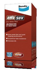
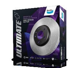
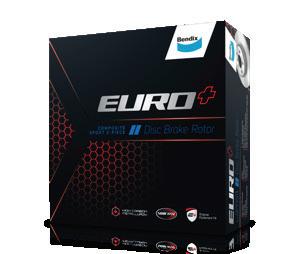
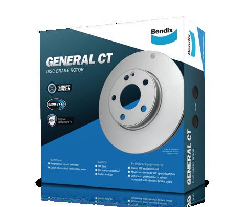
FOR EVERY DRIVING STYLE,
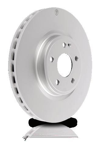
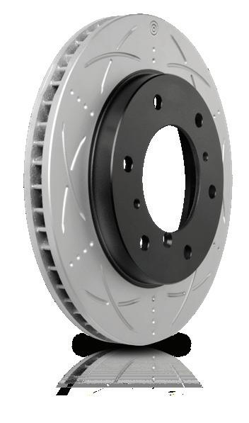
BENDIX HAS THE RIGHT BRAKE PAD & DISC BRAKE ROTOR.
To achieve the best possible braking performance and stopping distance, it’s important to match the driving style and vehicle with the right brake pad and disc brake rotor formulation. You can find and fit the right Bendix brake pad and disc brake rotor for virtually every application with absolute confidence. Check online for your vehicle.
Find solutions for every brake job at www.bendix.com.au
Or freecall the Bendix Brake Advice Centre on 1800 819 666 Bendix is a trademark of Garrett Advancing Motion Inc.
TechTalk is published by: Victorian Automotive Chamber of Commerce - Technical Services. VACC House 650 Victoria Street, North Melbourne VIC 3051
Matthew Corney, Matthew Tan, Michael Massey, Michael Wakefield and the feedback of VACC members and MotorTech subscribers.
Disclaimer This publication is distributed with the understanding that the authors, editors and publishers are not responsible for the results of any actions or works of whatsoever kind based on the information contained in this publication, nor for any errors or omissions contained herein. The publishers, authors and editors expressly disclaim all and any liability to any person whomsoever whether a purchaser of this publication or not in respect of anything and of the consequences of anything done or omitted to be done by any such person in reliance, whether whole or partial upon the whole or any part of the contents of this publication.
Information on products and services contained in this magazine is published as a service. It does not imply the endorsement of any product or service by the Chamber.
Copyright Tech Talk is copyright and no part may be reproduced without the written permission of VACC.
Subscriptions VACC adheres to its obligations under National Privacy Principles legislation.
Advertising Advertising accepted for publication in Tech Talk is subject to the conditions set out in the Tech Talk rate card, and the rules applicable to advertising.
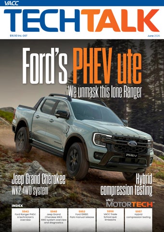
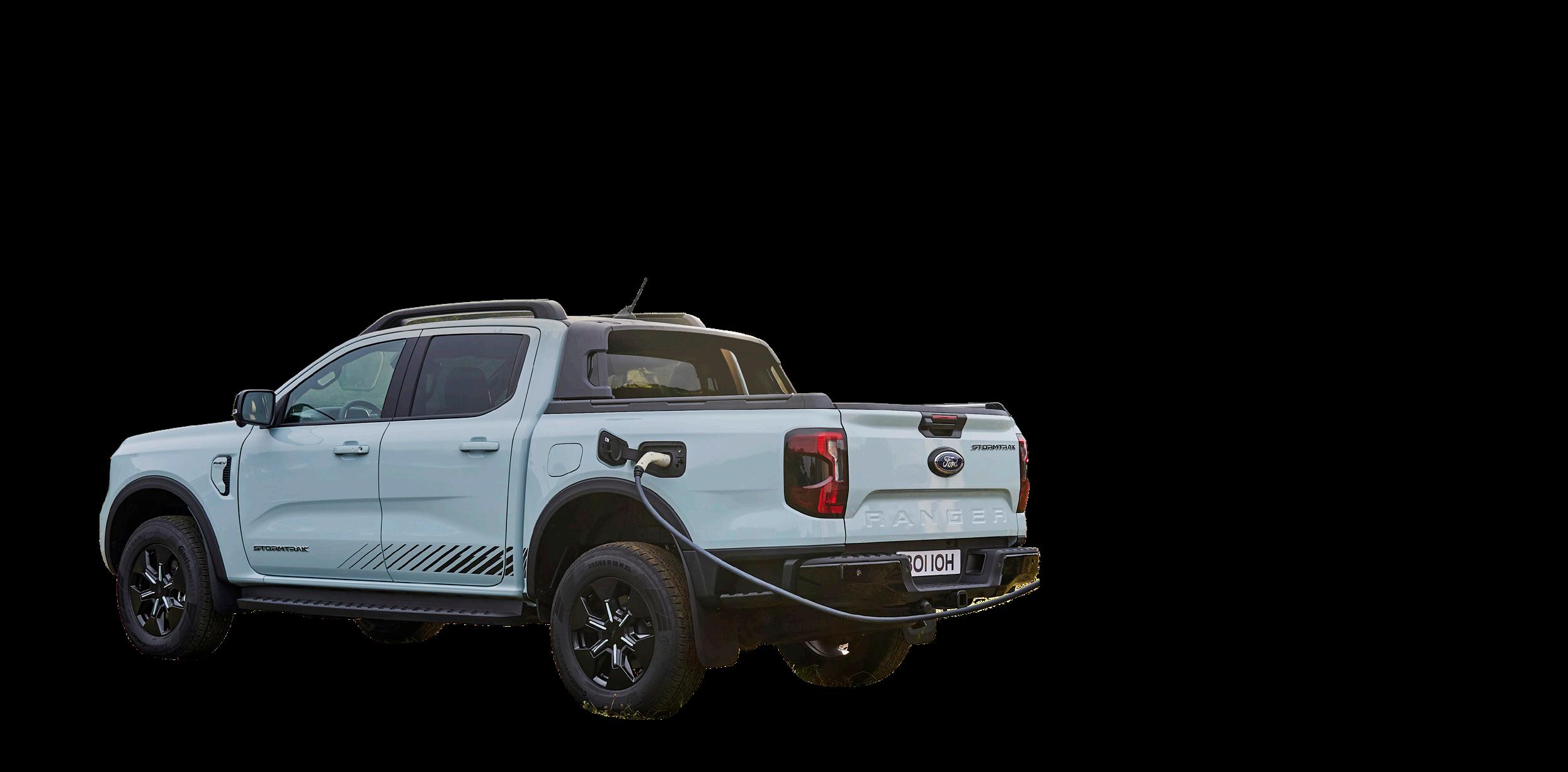
‘Timing is everything’ is a piece of folk wisdom that suggests the success of an action depends less on what you do or how you do it, and more on when you do it. In relation to the new trend of Plug-in Hybrid (PHEV) dual-cab 4WDs in the Australian market, being first will get you remembered as an innovator, and all that follows will be compared to this new benchmark.
The Ford PHEV Ranger was the third to be released and only stacks up ok for the price. However, it seems easy enough to work on once you know what you are looking at.
The BYD Shark 6 was the first PHEV ute to be released into the Australian market, with the first deliveries in January 2025. Its excellent
performance, good EV range and affordability make it popular. See TechTalk March 2026 for more details. Next was the GWM Cannon Alpha PHEV in April 2025, which featured better towing and a more traditional mechanical 4WD system. Then, in June 2025, the Ford Ranger PHEV is released, which seems to have prioritised its core towing and off-road capabilities over its electric drivetrain potential, which some could say does not stack up well against the benchmarks set by the new competition.
Recently, VACC had access to the Stormtrak version of the new Ranger PHEV, which is the current top-ofthe-line model with all available options for an inspection and review.
Driveline Overview
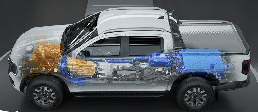
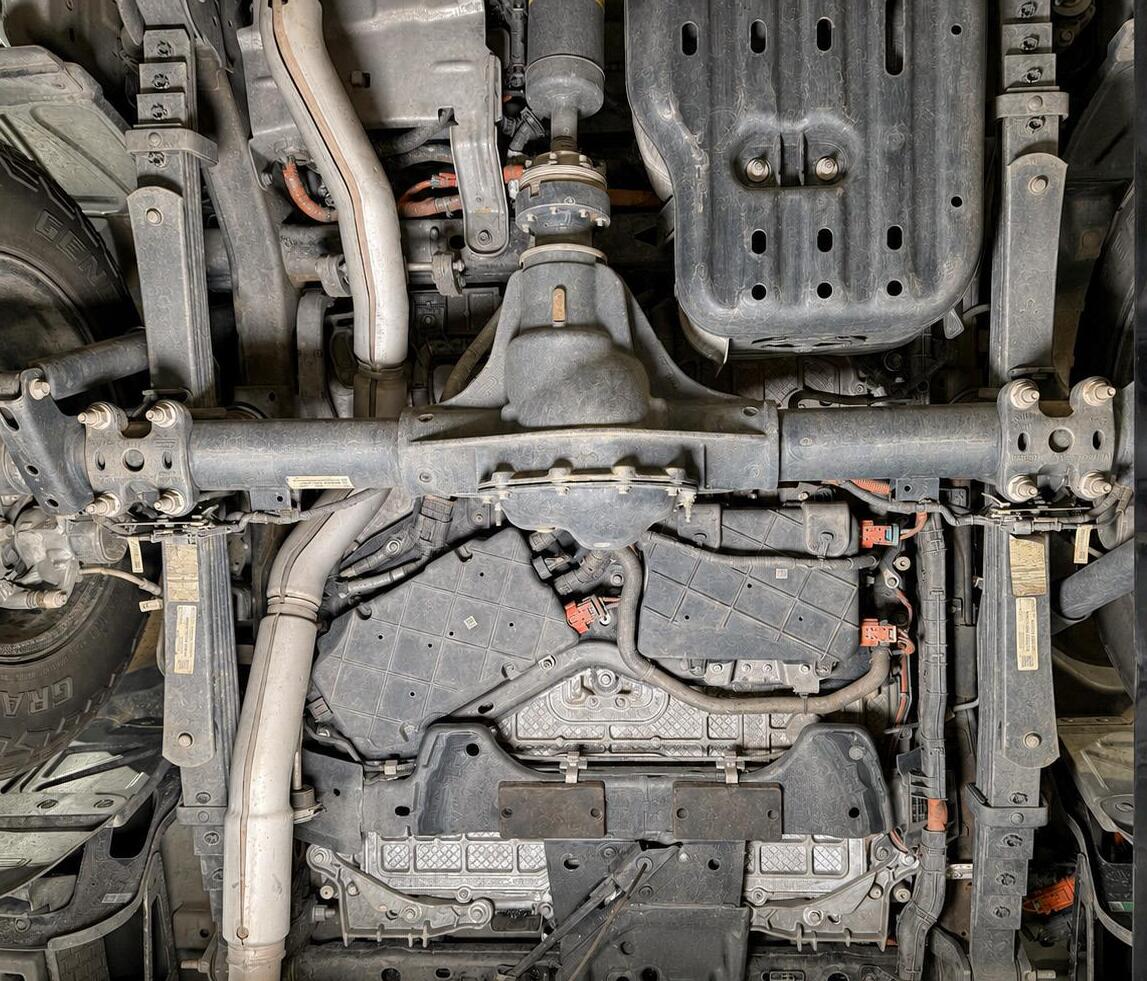
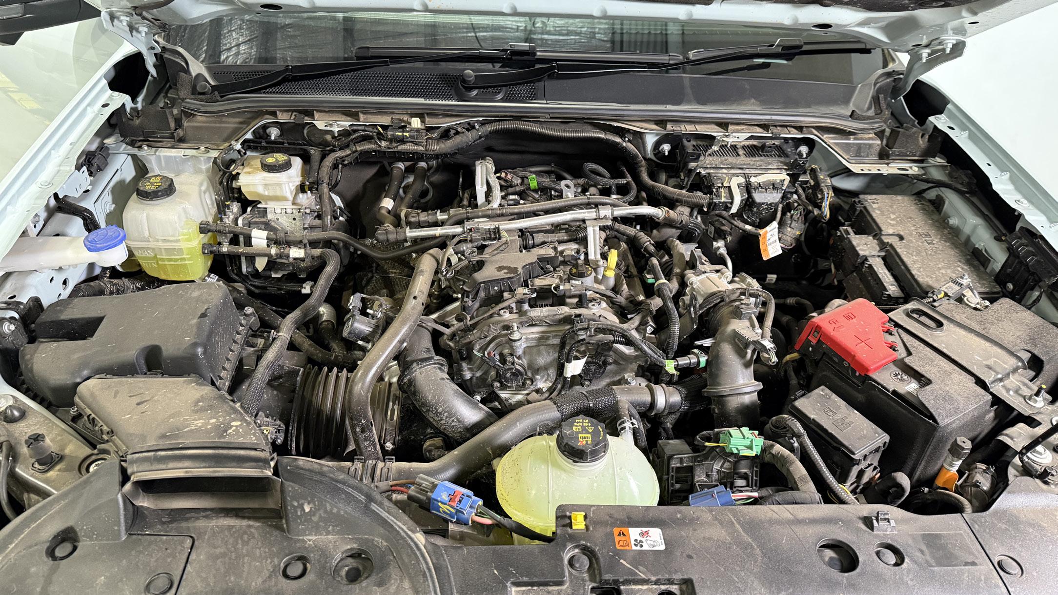
The Ford Ranger PHEV drivetrain is built around a 2.3-litre EcoBoost turbocharged petrol engine, a variant of the engine used in the Mustang from 2015 to current models and in the Focus from 2020 to 2022. A 75kW electric motor is mounted between the engine and the 10R80 10-speed automatic transmission, which Ford calls a Modular Hybrid Transmission (MHT). This allows for a standard 4WD system with a low-range transfer case, the same as its diesel-powered brethren. It uses an 11.8 kWh lithium-ion battery mounted between the chassis rails under the tray. See Diagram 1
DIAGRAM 1 Driveline component locations
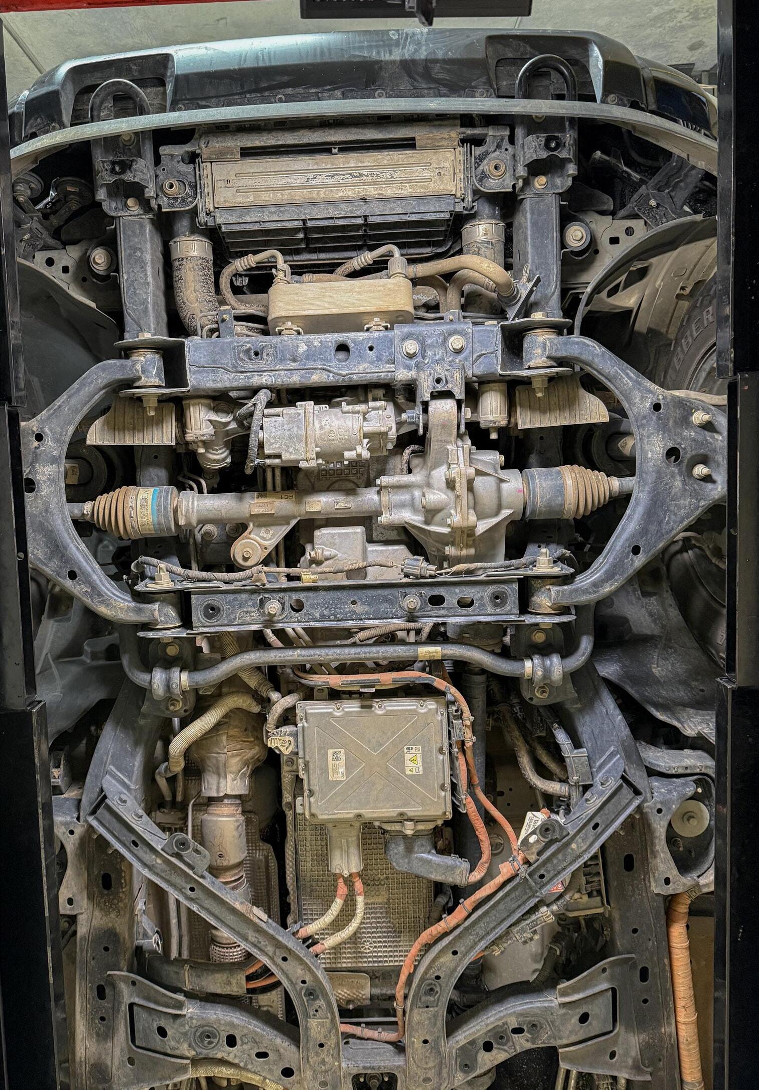
2 Front under body service points
Inverter System Controller (SOBDMC)
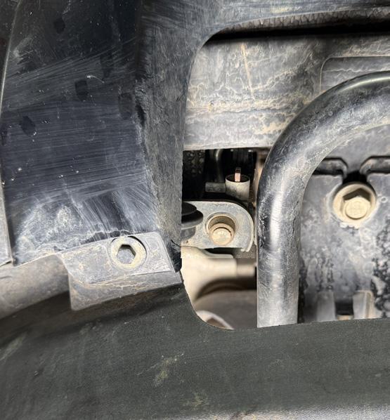
Radiator drain plug
Engine sump plug
Front diff filler plug
Front diff drain plug
DIAGRAM
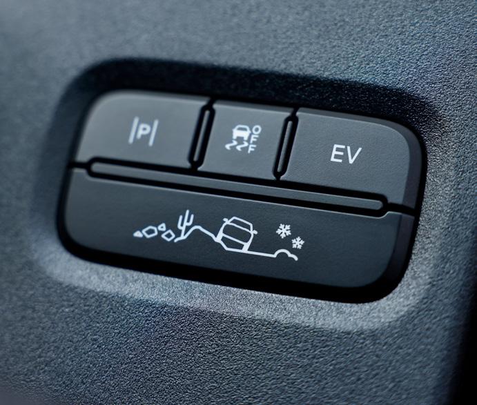
The operating voltage for the system is not stated; the OE information describes the system as high-voltage, so it can be assumed this is not a mild hybrid. So, the appropriate high-voltage qualification will be needed for RWC inspections and service information. The drivetrain features four specific EV modes, alongside standard terrain settings, to manage power delivery, which can be selected via a set of buttons on the centre console. See Diagram 3
• Auto EV: Automatically blends petrol and electric power for the best efficiency.
• EV Now: Operates purely on electric power for silent driving.
• EV Later: Preserves the current battery charge for use at a later time.
• EV Charge: Uses the petrol engine to recharge the battery while the vehicle is in motion. This system uses many different high-voltage components spread around the vehicle with confusing acronyms used to describe them.
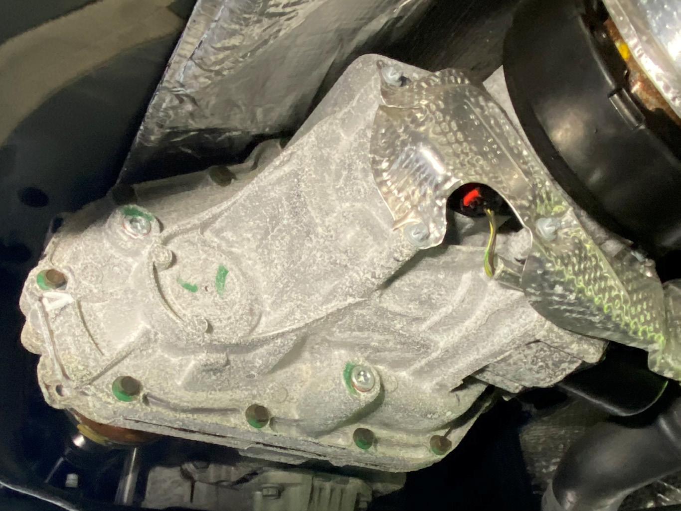
The SOBDMC (Secondary OnBoard Diagnostic Control Module C) is the Inverter System Controller responsible for monitoring and controlling high-voltage battery management and charging functions and is mounted under the transmission. See Diagram 2
The SOBDM (Secondary OnBoard Diagnostic Control Module) manages charging functions, including AC charging, charging schedules, and charge port indicators and is mounted under the battery. See Diagram 4 In front of the battery is the DC/ AC Inverter, used for the Pro Power Onboard system that acts as a
mobile generator, converting DC power from its 11.8kWh battery to AC power. It supports up to 6.9kW total power output, featuring two 15-amp 240V outlets in the tray and one 10-amp outlet in the cabin, allowing it to power tools and appliances. See Diagram 4 Then there is the DC/DC converter, which steps down the high voltage to 12 volts to power the low-voltage system around the vehicle. See Diagram 1 Engine cooling system
An interesting feature of the engine that some may not be aware of is the use of a cold-side thermostat. It works in the same way as a conventional wax thermostat, but it is placed at the inlet side of the engine (lower radiator hose), rather than the outlet side (upper radiator hose). It works by regulating the coolant returning from the radiator to the engine, rather than managing the hot coolant leaving the engine. This system appears to be used across the entire Ecoboost engine family and has caused issues overseas with incorrect aftermarket thermostats being fitted.
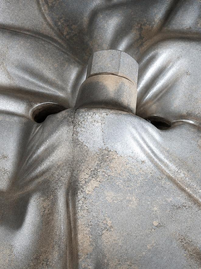
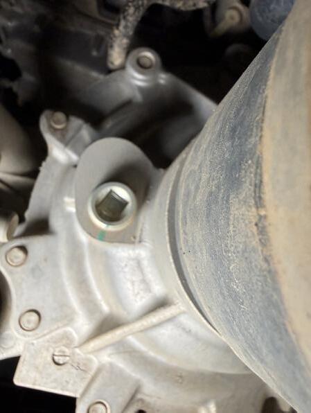
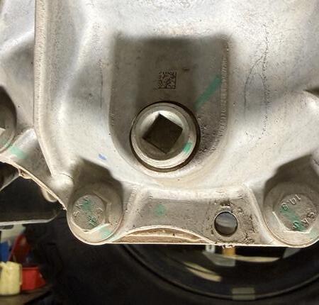
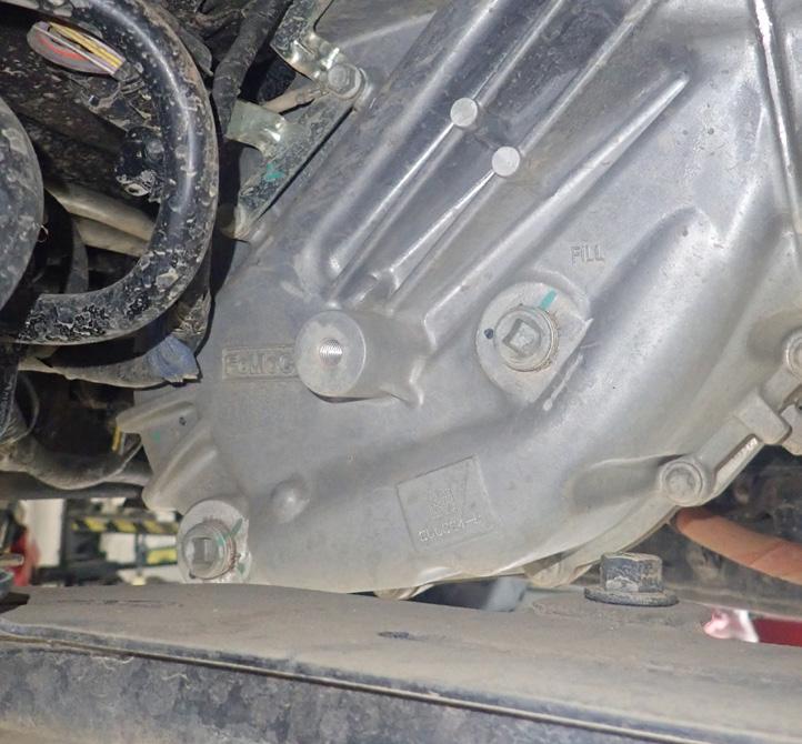
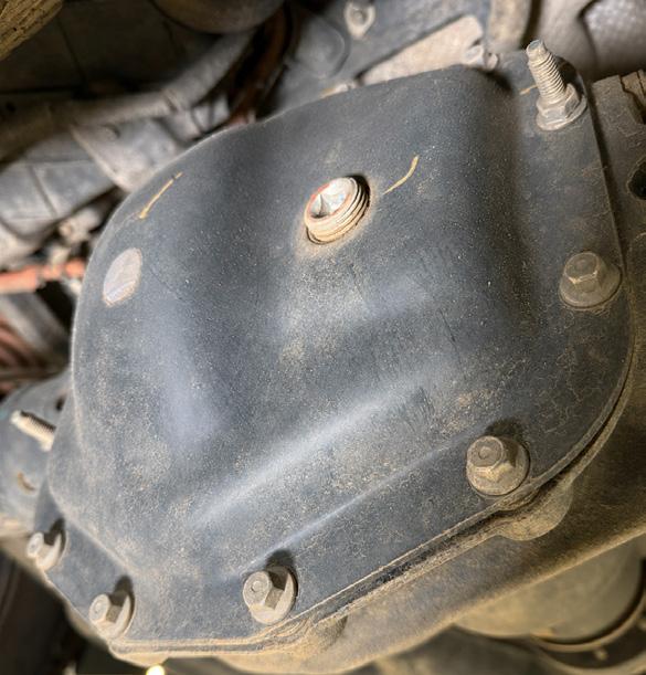
NOTE: There is no drain plug for the final drive. You will have to remove the rear cover or suck out the old oil via the refill and level plug.
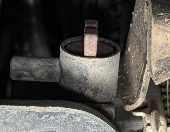
From a service perspective the drain for the radiator is hard to find, but it is at the right hand front behind the bumper and as a red tap. See Diagram 2 Hybrid cooling system
As with all other hybrid vehicles, there are extra components that require their own cooling system. The battery, onboard charger, and
(Use
Nm (Use New Plug)
Nm (Use New Plug)
Wheel Alignment
Use the specifications in the following article: Ford Ranger PY Features and Specifications TechTalk March 2024, page 5525
Brake Specification
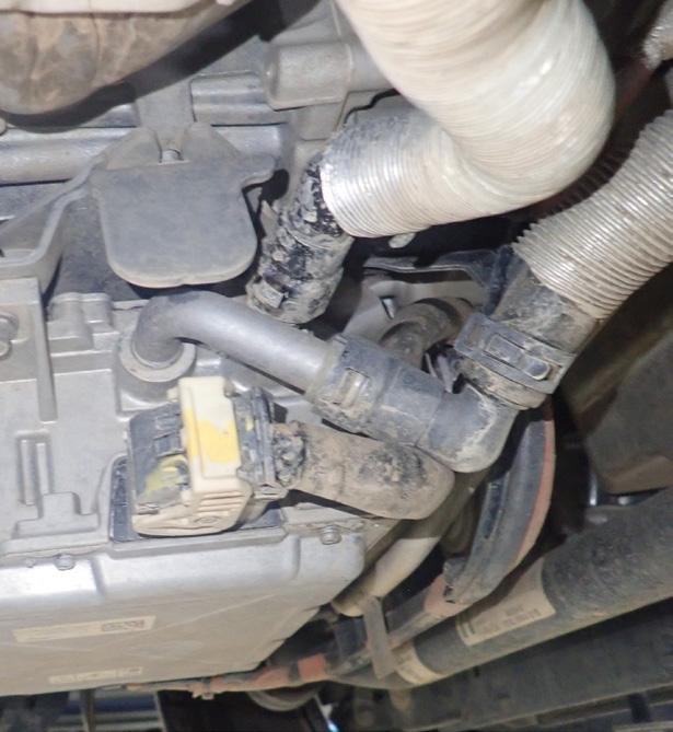
DC/DC inverter are liquid-cooled, so there are additional electric coolant pumps and coolant hoses running from the front of the vehicle to the components in the rear. In front of the main engine radiator is a smaller radiator for the HV cooling system. Draining of this system requires the removal of a quick-release fitting on the inverter unit SOBDMC under the transmission. See Diagram 2
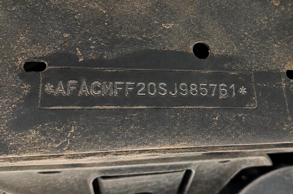
into the chassis rail on the outer right side. It is also visiable through the windscreen.
Transmission Service.
As this vehicle uses a variant of the 10R80 transmission, its service seems similar to that of other vehicles with this transmission. See the following article for more information.
Ford 10R80 10-speed Auto: ATF Drain and Refill Procedure.
TechTalk June 2020, page 4878
DIAGRAM
DIAGRAM
DIAGRAM
The VIN is stamped
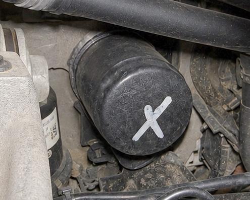
The engine oil filter can be access via the left front wheel arch.
This is hard to see from under the bonnet.
Fuel System
The fuel filter is a part of the fuel pump and sender unit in the fuel tank and is claimed to be a lifetime filter. There are no convenient access panels to remove the fuel pump assembly. Fuel tank removal looks like it is a relatively straightforward job.
Conclusion
The Ford Ranger PHEV Stormtrak is a nice car with some great features. It has all the performance you need, and it has a good level of fit and finish from the South African factory where the PHEV models are made. The adaptable racking system in the tray and
on the roof makes carrying long gear easy, and the 240 V plugs in the cabin and tray will be great at the camp or work site. And it maintains the benchmark 3,500kg towing and high payload capacity of the conventional Rangers. However, it seems to be lacking some features available on its more affordable competitors. You can’t give the high-voltage battery a quick top-up from the growing network of fast chargers around the country, as it only supports Type-2 AC charging. The HV battery is the smallest in the PHEV class, with roughly 31–45km of realworld EV range, which is barely enough to commute with when
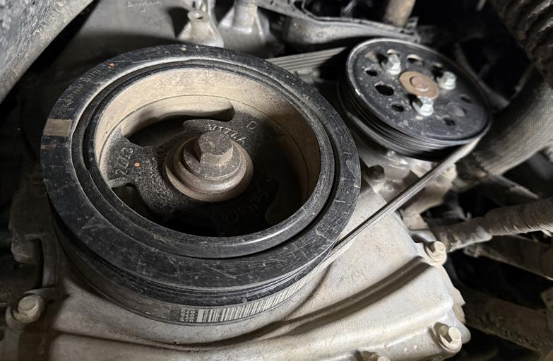
DIAGRAM 9 Coolant pump belt is the only belt
The advantage of a PHEV system is the simplicity of the belt layout. The DC/ DC converter replaces the alternator, and the AC compressor is driven by an HV motor. The power steering is electric. I would not be surprised if the coolant pump is replaced with an electric drive in future models
compared to the others, which have approximately 100km of EV range. It also lacks the sheer acceleration performance that the other more affordable PHEV utes can unleash. From a service and repair perspective, all of the service points seem easy enough to access, if not, no worse than any other Ranger. There seems to be room for an average-sized human hand to be able to fit and reach most components. The PHEV components are all easy to access once the spare wheel is removed. I think Ford might have come to the party late with a PHEV system that’s too conservative and expensive compared to the competition. The number of new vehicles with high-voltage drivelines entering the Australian market is growing rapidly. It will be interesting to see whether the legacy manufacturers can adapt fast enough to what customers now expect.
12V battery
Fuse and relay box
Engine number VIN location Engine compartment fuse box
Hybrid system coolant reservoir
AC service points
Engine coolant reservoir
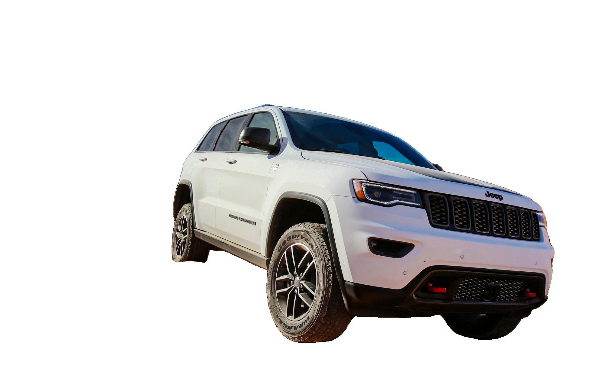
The Jeep Grand Cherokee WK2 has a polarising reputation in Australia, often described as a vehicle that offers “exceptional bang for your buck” and is respected for its ability to handle difficult 4WD tracks right off the showroom floor, though it also has some reliability issues. This is an overview of the WK2 4WD systems and diagnostic tips for common problem areas.
Jeep has had many 4WD systems over the years, and the Grand Cherokee WK2 features two main types of transfer cases in three different configurations. They are categorised by their capability, ranging from lightduty all-wheel drive to heavyduty off-road systems. These are called Quadra-Trac I, QuadraTrac II, and Quadra-Drive II. Quadra-Trac
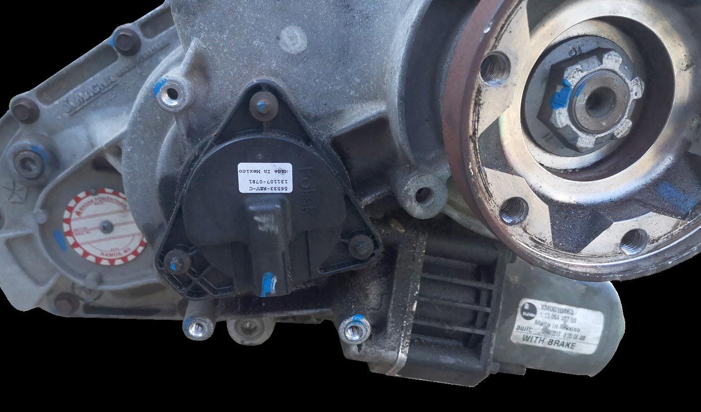
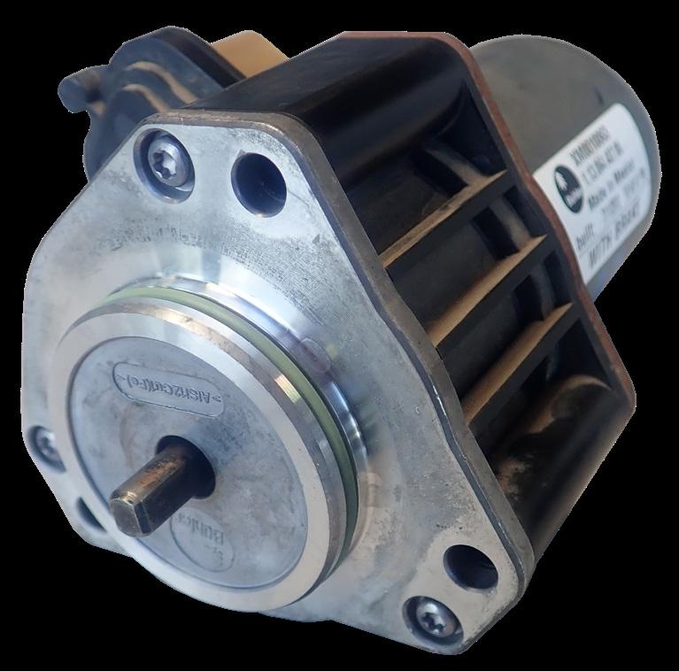
Quadra-Trac refers to Jeep’s brand of full-time four-wheel-drive (4WD) or all-wheel-drive (AWD) systems. It automatically alters the torque split between the front and rear axles, via the shift motor mounted at the rear of the transfer case. See Diagrams 2
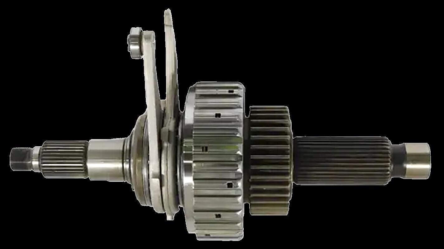
This motor will alter the clamping force applied to a wet multi-plate clutch inside the case. See Diagram 3
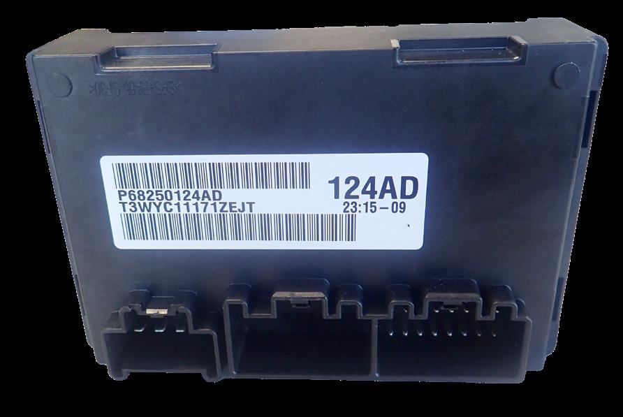
The signals to the shift motor are generated by the drivetrain control module based on inputs from various vehicle sensors. This module is mounted under the front passenger seat. There is a potentiometer-style position sensor at the rear of the
transfer case that reports the position of the transfer case shift mechanism. See Diagrams 2 & 5
Quadra-Trac I uses the singlespeed MP2010 transfer case and is found on base models, most commonly the Laredo. There is no low-range option.
Transfer case for all of the different variants of the
Jeep Quadra-Trac/Quadra Drive II transfer case
DIAGRAM 1
4WD systems are similar.
Drain plug
Fill and level plug
DIAGRAM 3
Wet clutch assembly and actuation levers
As the shift motor rotates it will move the two levers. When spread apart, they will apply more force to the clutch pack. This is how the the torque to the front or rear axles is altered depending on tyre grip conditions.
Quadra-Trac Active on Demand uses the single-speed MP3010 transfer case, which is commonly used in high-performance SRT models, to handle the higher torque output.
Quadra-Trac II uses the twospeed MP3023 transfer case, which also allows the driver to select low range via an added planetary gear set. The same shift motor is used and is commanded to rotate further to engage low range.
Quadra-Drive II
Quadra-Drive II is Jeep’s most advanced, full-time four-wheeldrive system designed for superior off-road capability and traction. It uses the same MP3023 transfer case as in the Quadra-Trac II system,
with the addition of an Electronic Limited Slip Differential (ELSD) in the rear axle for improved offroad capability. This system is standard on Summit, Trailhawk trim levels, and optional on V8 Overland/Limited models.
The trouble
This system has been known to produce common faults that can cause the 4WD lights to flash and a “Service 4WD System” message to appear on the instrument cluster, along with various drivability symptoms.
Shift motor failure
As the shift motor is constantly driven forward or backward to adjust clutch pressure, it tends
to cause trouble after a while. The following code is common. C1403-92 - Transfer Case Range Position Sensor – Performance or Incorrect Operation
This code could have many causes, but is commonly a failure of the shift motor. Depending on where in its travel it fails, it can present with various symptoms in addition to the fault codes.
If it fails with the clutch fully released, then the transfer case will only direct drive to the rear axle. If it fails anywhere else in its travel, the clutch will be partially engaged, but will not adjust to the changing drive requirement during cornering. This will cause shuddering and driveline binding and will prematurely wear out the transfer case clutch if left unrepaired. The transfer case could also be stuck in 4 Low if the shift motor fails
The OE workshop manual does not provide any testing for the shift motor and uses an eliminationbased diagnostic process, replacing parts until the problem goes away. We have checked the resistance of a known-good shift motor, and the specifications are as follows.
• Between terminals 1 & 4 = 2.3Ω
• Between terminals 2 & 3 = 4.9Ω
See Diagram 8
The shift motor can be unbolted from the transfer case, and a large screwdriver can be inserted into the slot of the shift mechanism drive. You should be able to
Front Axle
This clutch assembly is used in all variants of the WKII transfer case
Rear Axle
Transfer case position sensor
Transfer case shift motor
Transfer case shift motor drive shaft. It can be fitted in any position.
Diagnostic code list for 4WD system
Code Description
C140A-13 Transfer Case Motor Control – Circuit Open
C140A-92 Transfer Case Motor Control – Performance or Incorrect Operation
C140E-00 Transfer Case Motor Blocked
C1403-8F Transfer Case Range Position Sensor – Erratic
C1403-11 Transfer Case Range Position Sensor – Circuit Short to Ground
C1403-12 Transfer Case Range Position Sensor – Circuit Short to Battery
C1403-92 Transfer Case Range Position Sensor – Performance or Incorrect Operation
C1406-11 Transfer Case Brake Control – Circuit Short to Ground
C1406-12 Transfer Case Brake Control – Circuit Short to Battery
C1406-92 Transfer Case Brake Control – Performance or Incorrect Operation
C1415-92 Transfer Case Motor Current – Performance or Incorrect Operation
Possible Cause
Shift motor control A or B circuit open or high resistance; circuit shorted to voltage or another circuit; faulty transfer case shift motor; wiring or connector faults; faulty DTCM
Shift motor control circuits shorted to ground or another circuit; faulty transfer case shift motor; wiring or connector faults; faulty DTCM
Mechanical transfer case issue; faulty transfer case mode sensor; faulty transfer case shift motor; wiring or connector issues; faulty DTCM
5volt supply circuit faults; sensor signal or return circuit faults; faulty transfer case mode sensor; wiring or connector issues; faulty DTCM
Mode sensor signal short to ground; 5volt supply circuit faults; faulty mode sensor; wiring or connector issues; faulty DTCM
Mode sensor signal short to voltage or another circuit; faulty transfer case mode sensor; wiring or connector issues; faulty DTCM
Mode sensor wiring or connector faults; faulty transfer case mode sensor; transfer case mechanical issue; faulty DTCM
Battery solenoid supply circuit faults; step motor control circuit faults; faulty shift motor; wiring or connector issues; faulty DTCM
Battery solenoid supply circuit faults; step motor control circuit faults; faulty shift motor; wiring or connector issues; faulty DTCM
Shift motor control circuits shorted to voltage or another circuit; mechanical resistance in transfer case; faulty shift motor; faulty DTCM
C1438-00 Transfer Case Differential Clutch Worn Worn transfer case clutch; transfer case differential damage
C1444-00 Transfer Case Motor Overuse
C1472-92 Transfer Case Clutch Control – Performance or Incorrect Operation
Driving in adverse conditions; selector switch wiring issues; faulty transfer case selector switch; faulty DTCM
PCM, TCM, or ABS data not received; incorrect clutch kiss point; transfer case mechanical issue
C1476-00 Transfer Case Clutch Position Out of Range Clutch kiss point not learned correctly; shift motor or sensor circuit faults; faulty mode sensor; faulty shift motor; faulty DTCM
C1477-4B Transfer Case Clutch – Over Temperature
Driving in adverse conditions; low or degraded transfer case fluid; shift motor circuit faults; worn clutch; faulty DTCM
C2108-11 Drivetrain Supply Voltage – Circuit Short to Ground 5volt supply circuit shorted to ground; faulty shift motor; faulty DTCM
C2110-11 Sensor Supply 1 Voltage – Circuit Short to Ground 5volt supply circuit shorted to ground; faulty shift motor; faulty DTCM
C2110-12 Sensor Supply 1 Voltage – Circuit Short to Battery 5volt supply circuit open or shorted to voltage; sensor return circuit faults; faulty mode sensor; faulty DTCM
C2129-16 Battery Voltage – Circuit Voltage Below Threshold Charging system DTCs present; fused B+ circuit open or high resistance; ground circuit faults; faulty DTCM
C2129-17 Battery Voltage – Circuit Voltage Above Threshold Charging system DTCs present; faulty DTCM
C2201-00 FDCM/DTCM Internal
C2206-00 Vehicle Configuration Mismatch
C2221-00 ELSD DTC Present
U0001-00 CAN C Bus
U0100-00 Lost Com with ECM/PCM
U0101-00 Lost Com with TCM
U0121-00 Lost Com with ABS Module
U0136-00 Lost Com with ELSD
U0140-00 Lost Com with BCM
U0212-00 Lost Com with Steering Column Control Module
U0401-00 Implausible Data Received from PCM
U0402 Implausible Data Received from TCM
U0415 Implausible Data Received from ABS
U0422 Implausible Data Received from BCM
Internal DTCM failure
Incorrect vehicle configuration; faulty or misconfigured DTCM
DTCs present in the Electronic Limited Slip Differential (ELSD)
CAN C bus open or short; CAN related module; splice or connector fault
CAN communication fault; wiring or connector issues
CAN communication fault; wiring or connector issues
CAN communication fault; wiring or connector issues
CAN communication fault; wiring or connector issues
CAN communication fault; wiring or connector issues
CAN communication fault; wiring or connector issues
PCM or BCM DTCs present; faulty DTCM
BCM misconfiguration; TCM DTCs present; wiring or connector issues
BCM or ABS DTCs present; faulty DTCM
BCM, PCM, or CAN bus DTCs present; faulty DTCM
U0429 Implausible Data Received from Steering Angle Sensor CAN bus fault; SAS DTCs present; faulty DTCM
U0437 Implausible Data Received from ELSD
ELSD, BCM, or CAN bus DTCs present; faulty DTCM
DIAGRAM 5
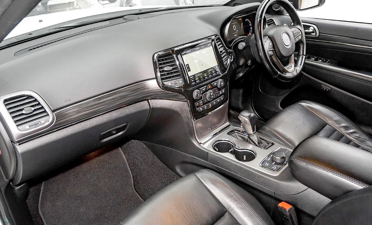
Component locatons in the cabin
The Drivetrain Control Module (DTCM) is mounted under the front passenger seat.
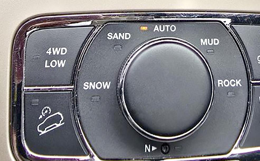
The 4WD Low button is only on variants with transfer case with the low range planary gear set fitted.
This mode switch will alter the traction control system and the torque split of the transfer case.
rotate the mechanism easily. If not, there may be an internal issue with the transfer case.
With a compatible diagnostic tool attached and reading the live data you should see the reading for the position sensor change, when the mechanism is rotated. There is no specifications for the changing resistances of the sensor.
DIAGRAM 6
Industry feedback suggests that if the shift motor has failed, it is
Jeep Grand Cherokee WK2 4WD system wiring diagram
This button will allow you to select Neutral if the vehicle needs to be towed.
recommended to replace the drive train control module as well. This is due to the additional current the failing shift motor draws, which damages the module even though it remains operational.
The wiring diagram below is compatible with all variants of the 4WD system.
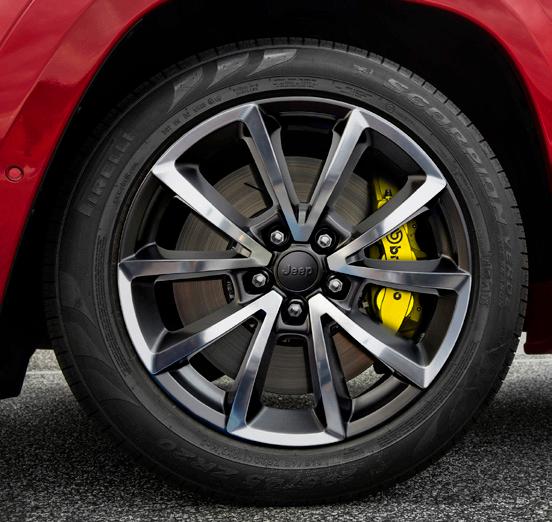
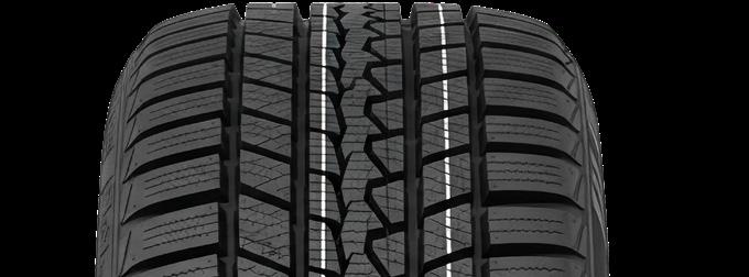
Check that all tyres are the same brand and model, have the same tread depth, and are inflated to the correct pressure.
If the tyres are different brands, or if you want to be sure, measure the tyre circumference at the centre of the tread with a flexible tailor’s measuring tape or a piece of string.
There have been reports of shift motors being replaced, only for the vehicle to return soon after with a failed module.
As a rule of thumb, all tyres should be within 6 mm of each other.
The drivetrain control module is plug-and-play with no programming required, and the shift motor can only be fitted in one way without timing. However, you will have to conduct a “DTCM non-volatile reset command” with a compatible diagnostic tool.
Mismatched tyre sizes
This is an issue with many AllWheel-Drive vehicles that lack a central differential. If the tyres on one axle are a different
size or are excessively worn compared to the other axle, this will cause a constant difference in rotational speed, which can prematurely wear out the transfer case clutch assembly.
The Quadra-Trac II and QuadraDrive II systems are highly sensitive to tyre circumference. Using different-sized tyres or worn tyres paired with new ones causes the computer to think the vehicle is constantly slipping, which can burn out the clutch plates. This situation could present as jerking and shuddering through the driveline with clicking and binding noises while cornering.
If you are dealing with a vehicle with this situation, repair as required to clear any fault codes and ensure that all the tyres match. To reliably repair the situation, a new transfer case clutch is required, and it might be more economical to replace the transfer case.
To avoid this situation recurring, it is important to educate your customers and your staff about the damage that can be caused by mismatched tyres on All Wheel Drive vehicles. For more information, see the following article.
All Wheel Drive Tyre Replacement. TechTalk May 2016, page 4152
Kiss point relearn procedure
After carrying out repairs to clear some codes, you might have to perform the “Kiss Point Relearn Procedure”, which allows the system to learn the exact position where the transfer case clutch plates first make contact and begin to transmit torque. The steps are as follows.
1. Start the engine.
2. Place the transmission into neutral.
3. Depress the brake pedal firmly.
4. Turn the transfer case mode selector switch in the centre console to “Auto”.
5. With a compatible diagnostic tool, activate the “DTCM nonvolatile reset command”.
6. Place the transmission into Park.
7. Turn the ignition off.
8. Wait for 10 seconds, then turn the ignition back on.
9. Scan the vehicle for fault codes and clear them.
10. Select 4WD LOW, then select Auto on the transfer case mode selector switch.
11. Scan the vehicle for fault codes and clear them.
This article provides only a brief overview of some issues that can occur in the WK2 Grand Cherokee 4WD system. For more information, log onto VACC MotorTech or call VACC’s TechAdvisory Service.
Ford 10R80: Manual park release procedure
2018-Onward Ford Mustang
2019-Onward Ford Ranger
2019-Onward Ford Everest
As with many other modern transmissions the 10 speed Ford 10R80 has is no physical connection between the shift selector and the transmission, as the various ranges are selected electronically. Lucky, Ford has built in a manual park release to allow you to move the vehicle if power is removed. It is a simple procedure once you know how.
The 10R80 is used in the Ford Ranger, Everest and Mustang from 2018 to the current models and has a variable reputation depending on how they have been used. There are a few different selector types depending on the model which all seem to work in the same way.
Gear Selection
When a gear position is selected by the driver, the selector will send a signal via Can Bus to the PCM or TCM which will ensure that this request can be performed, based on information such as engine speed, vehicle speed, brake pedal position and transmission shift interlock systems. A signal will then be sent to the transmission, and the appropriate solenoids will be activated to engage the requested gear position. See Diagram 2
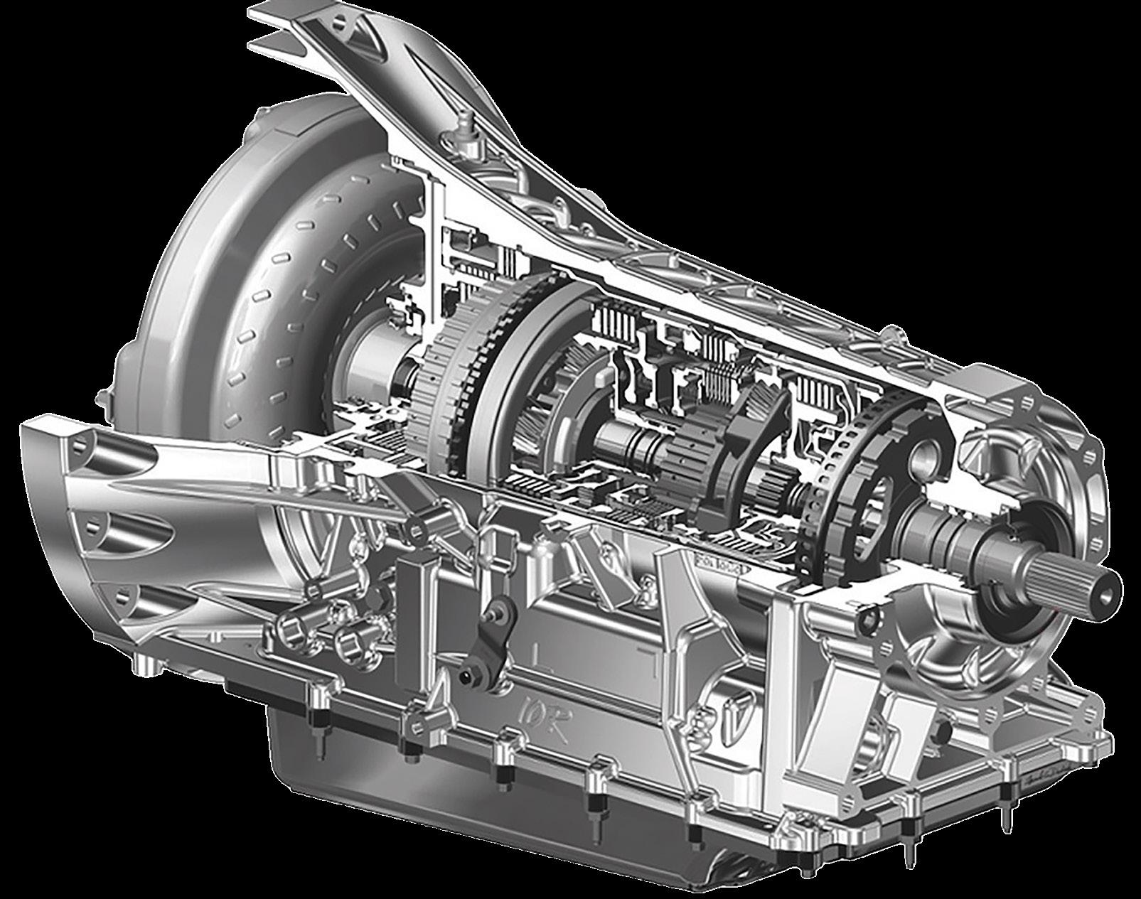
DIAGRAM 1 Cutaway view of a 10R80 transmission
Image: Ford
Image: Ford
This lever on the side of the transmission is connected to a cable that runs up into the cabin to disable the park mechanism.
Park mechanism
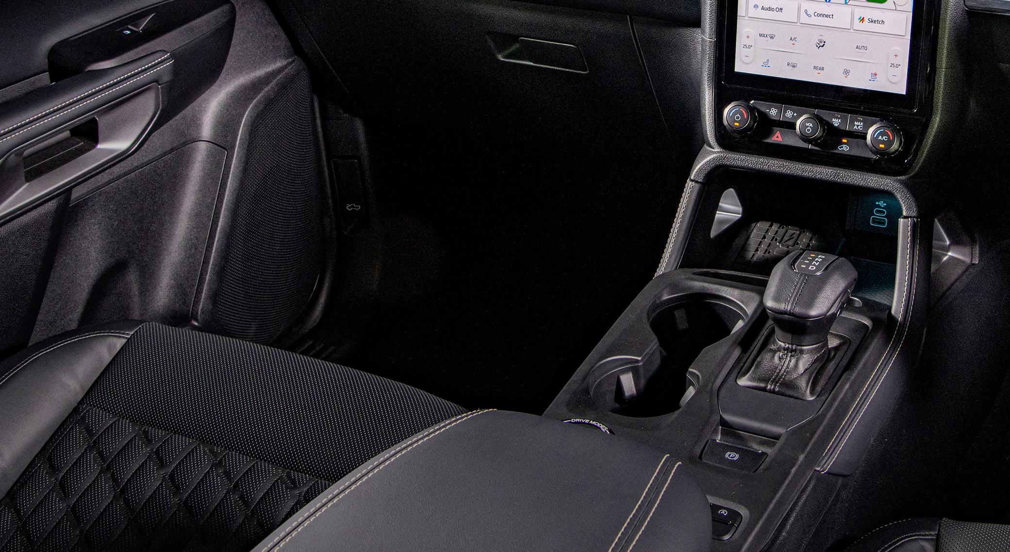
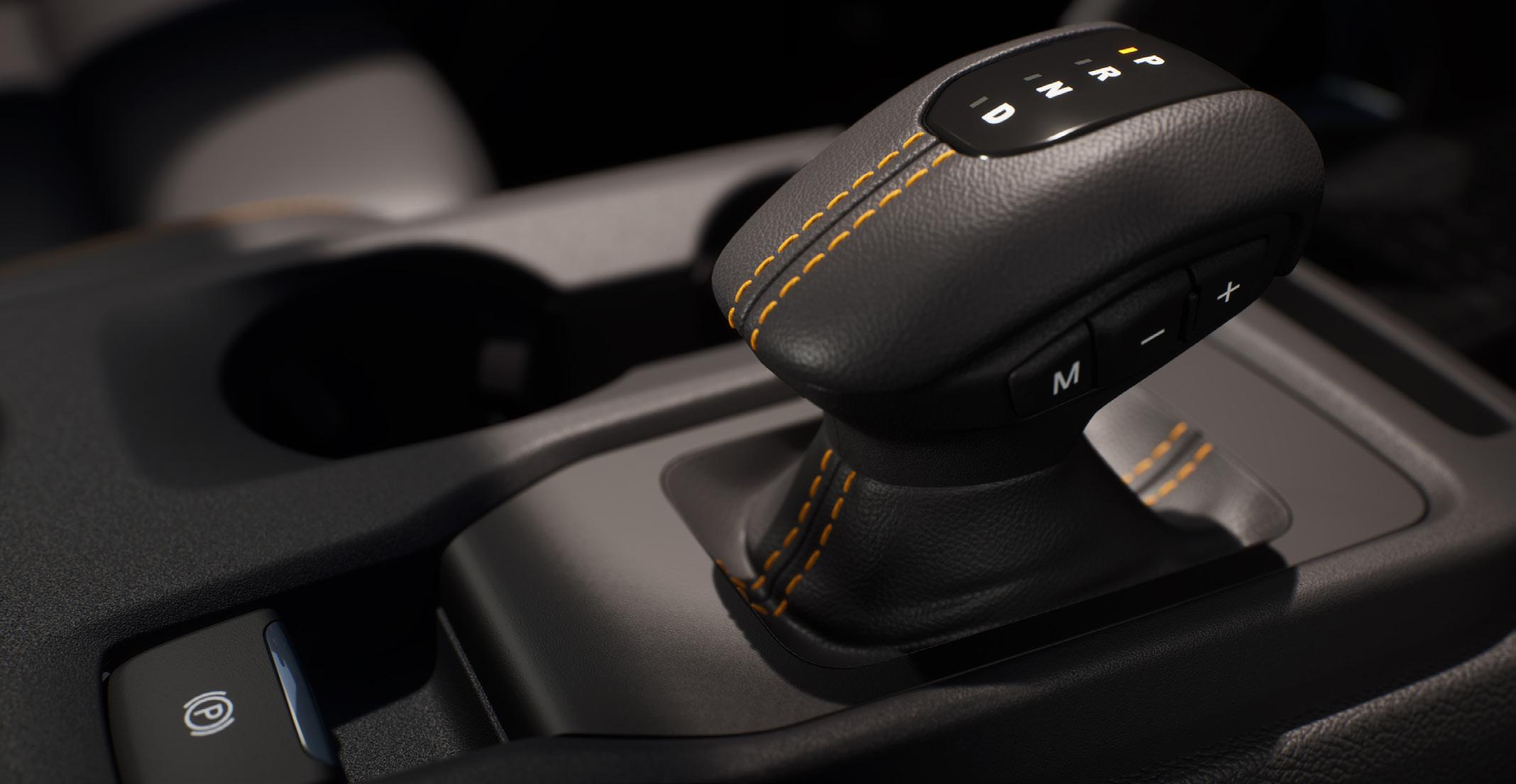
Traditional T-bar “stick” shifters for the automatic transmission are primarily featured on the lower-trim models of the Ford Ranger, while higher trim levels have an electronic shifter (e-Shifter), as shown. The e-Shifter is a short, stubby shifter that returns to centre after selecting a range. However, there seems to be a trend to revert to a T-bar shifter across most trim levels from early 2025 production. Other models could have a dial-type selector. This “shift-by-wire” technology enables advanced automated safety features, including Automatic Park, which engages the parking pawl without driver input under specific conditions.
No matter the type of shifter, it will still send a signal to request a change in the transmission selected range. There is no physical connection to the transmission.
The one mechanical link from the cabin to the transmission is the cable which runs from under the centre console to the lever on the side of the transmission. When this cable is pulled, it will override the park lock pawl valve and will keep the park pawl from engaging with the external teeth on the planetary gear carrier. See Diagram 1
Manual Park Release
The procedure is as follows.
1. Apply the parking brake.
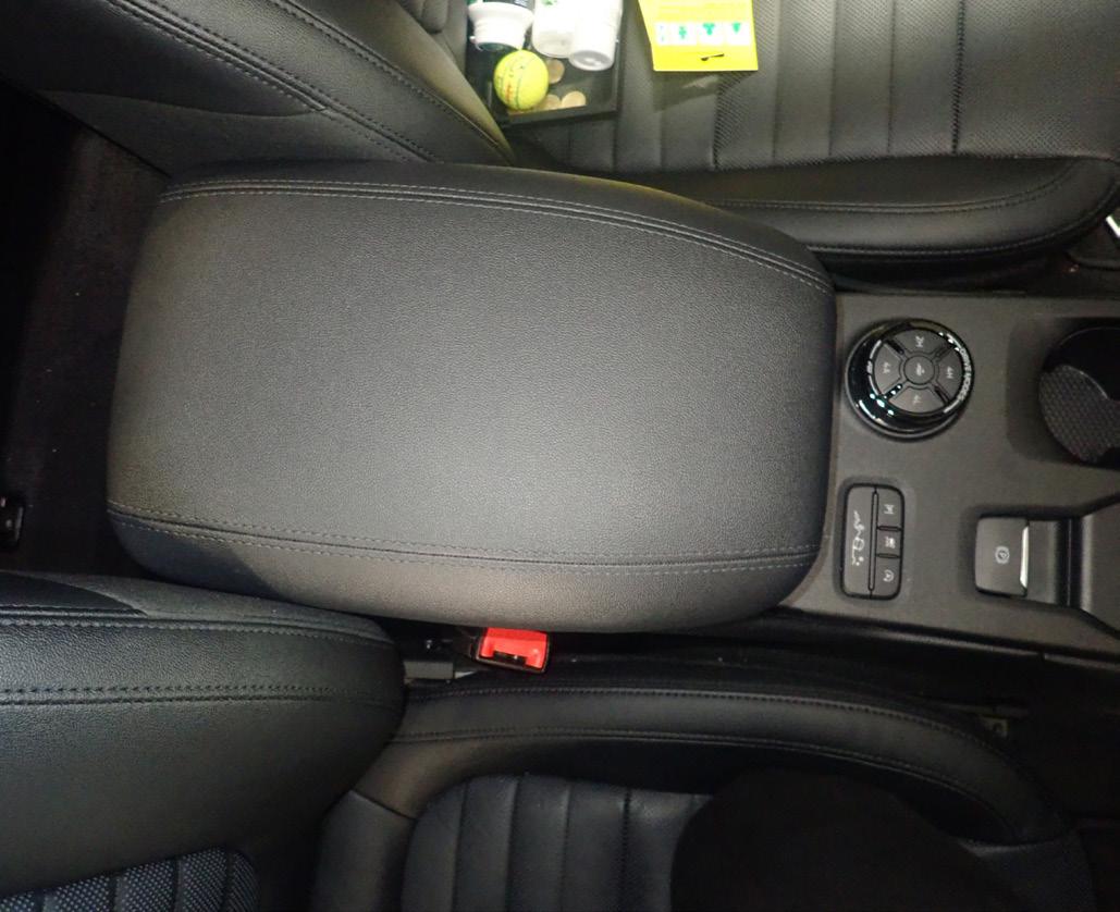
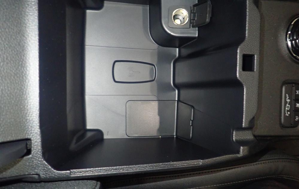
2. Open the centre console lid.
3. Remove the rubber mat
from the bottom of the storage area. See Diagram 3
4. Using an appropriate trim removal tool, remove the transmission park manual release access panel on the driver’s side at the bottom of the console storage area. See Diagram 3
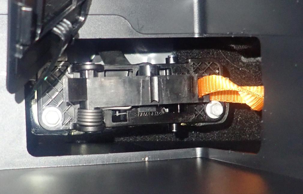
5. Release the tether or wire from the retention tab.
6. Switch the ignition on, but don’t start the engine.
NOTE: Don’t attempt this while the engine is running, as various components could be damaged.
If
7. With someone sitting in the driver’s seat, depress the brake pedal.
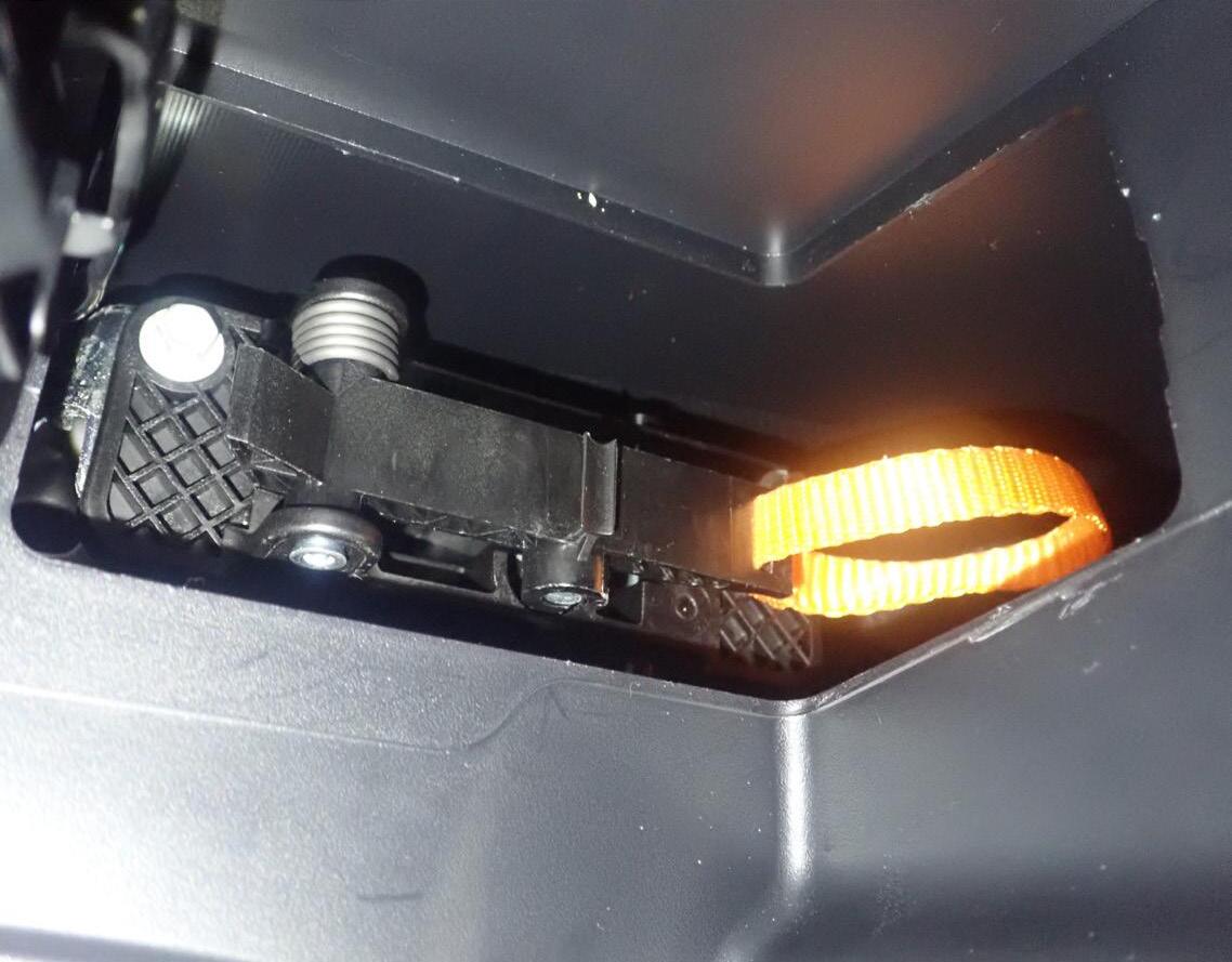
8. Pull the tether straight up until the handle locks into the “Park Override” position. This will place the transmission into “Neutral”. See Diagram 4
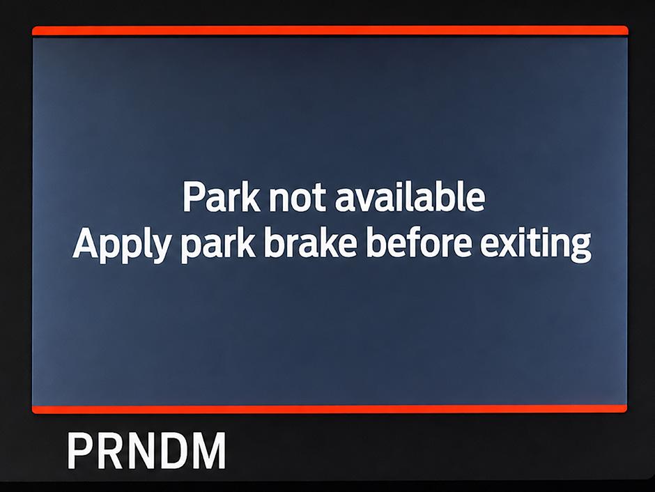
NOTE: A warning will be displayed on the instrument cluster. See Diagram 5
9. With your foot still on the brake, release the parking brake.
10. Turn the ignition off.
11. Disconnect the negative battery terminal.
After opening the console and emptying the vehicle owner’s worldly possessions, you may need to remove a rubber mat from the bottom of the storage area to reveal the cover for the park release.
NOTE:
the battery in the key fob goes flat, this is the area to place it to start the vehicle in the Ranger and Everest.
Image: Ford
With the cover removed, in this example, an orange strap or tether is attached to a spring-loaded lever. This lever is attached to the cable, which is connected to the other lever on the transmission’s side.
Deactivation
1. Connect the negative battery terminal.
2. With someone sitting in the driver’s seat, depress the brake pedal.
3. Pull the tether up to the end
Park is disabled warning DIAGRAM 5
of its travel to release it. Then maintain tension on the tether while it retracts back into its stowed position
4. With your foot still on the brakes, start the engine and confirm that “Park” is indicated on the instrument cluster.
This warning will be displayed on the instrument cluster when the manual park release is engaged. Ensure that the park brake is on or the wheels are chocked to prevent unexpected vehicle movement.
5. If so, refit the retention tab over the tether.
6. Refit the transmission park manual release access panel If you are planning on servicing this transmission there are various methods of ensuring the correct fluid level depending on the model and type of dip stick used. See the following article for more details. Ford 10R80:
Drain and Refill Procedure TechTalk June 2020, page 4878 For more service and diagnostic information on these and many other transmissions, log on to VACC MotorTech or call VACC’s TechAdvisory Service.
Hook a finger into the strap loop and gently pull up
VACC Trade School Light vehicle emission systems QUIZ
Since 1993, the VACC Skills Development Centre has been a leader in automotive apprentice training and employment in Victoria. VACC SDC develops training and assessment resources for Registered Training Organisations (RTOs) across Australia to provide automotive apprentices and their trainers with user-friendly, compliant, and up-to-date resources.
The following quiz questions are based on any assessment task from the unit of competency AURLTZ101, Diagnose and repair light vehicle emission systems, in AUR30620 – Certificate III in Light Vehicle Mechanical Tech. Let’s see if you can answer the questions your apprentice is being tested on.
Multiple-choice questions
1. If you discover the power cord to a gas analyser is damaged and has exposed wires, what is the required action?
A: Fix the wires with electrical tape.
B: Continue the test but do not touch the cord.
C: Tag-out the equipment, isolate it, and notify the supervisor immediately.
D: Use a different power outlet.
2. When working with fuel systems, what safety precaution must be taken regarding ignition sources?
A: Keep a heater nearby in cold weather.
B: Test systems away from flames, sparks, and other ignition sources.
C: Use a lighter to check for fuel vapour.
D: Ensure all electrical tools are plugged in nearby.
3. What is a primary control measure to reduce risk when working on an engine emission system while the engine is running?
A: Working in a sealed, quiet room.
B: Working in a well-ventilated area or using an exhaust extraction system.
C: Increasing the engine idle speed.
D: Wearing loose-fitting clothing for comfort.
4. What is the main purpose of the Evaporative Emission Control System?
A: To convert unburnt fuel and carbon monoxide into carbon dioxide and water
B: To prevent the release of gases from the engine crankcase to the atmosphere
C: To stop the release of hydrocarbons or fuel vapour into the atmosphere
D: To reduce the formation of oxides of nitrogen during combustion.
5. Which component in the fuel tank provides space for fuel expansion and cools/condenses fuel vapours?
A: Purge valve.
B: Charcoal canister.
C: Vapour space.
D: Fuel pump.
6. In the Crankcase Ventilation System, what are the gases that leak past the piston rings called?
A: Over-flow.
B: Blow-by.
C: Exhaust leak.
D: Purge-gas.
7. During a purge cycle in the evaporative system, what is drawn into the charcoal canister’s base?
A: Liquid fuel.
B: Fresh air.
C: Exhaust gases.
D: Engine oil.
8. What is the specific purpose of the Air Injection System?
A: To cool the exhaust manifold.
B: To oxidise any unburnt hydrocarbons.
C: To increase the boost of the turbocharger.
D: To inject fuel into the exhaust.
9. Under which engine condition is the PCV (Positive Crankcase Ventilation) valve forced closed by manifold and spring pressure?
A: Engine idling.
B: Engine at cruise (low load).
C: Hard acceleration, turbo boost, or engine backfire.
D: Engine driving at 2000 RPM (high load).
10. What precious metals are used in the framework of a reduction catalytic converter?
A: Gold and silver.
B: Copper and nickel.
C: Platinum and rhodium.
D: Iron and aluminium.
VACC and TACC apprenticeship programs are the largest employers of automotive apprentices in Victoria and Tasmania, and among the largest Australia-wide, helping fill skills shortages in our industry.
For more information about our apprenticeship programs and the training and assessment resources we produce, visit autoapprenticeships.com.au or call (03) 9829 1130.
How to compression test a hybrid engine
Back in the day, the list of basic diagnostic checks to assess an engine was short and relatively simple, but now the list has grown, and the simple checks are more difficult. One of these diagnostic procedures is the compression test, but with the rise of hybrid drivelines and hard-toreach spark plugs, it can be timeconsuming. However, it could give you the answers you need.
The basic layout of the four-stroke engine has not changed since it was introduced over 150 years ago; at its core, it acts as a gas pump. Air and fuel are drawn into the cylinders (Intake), then compressed (Compression), ignited to release energy and push the piston down (Combustion), and finally, the exhaust gases are expelled (Exhaust). See Diagram 2
For this gas pump to function properly, even though it might have various computer controls and a hybrid driveline, the pistons must
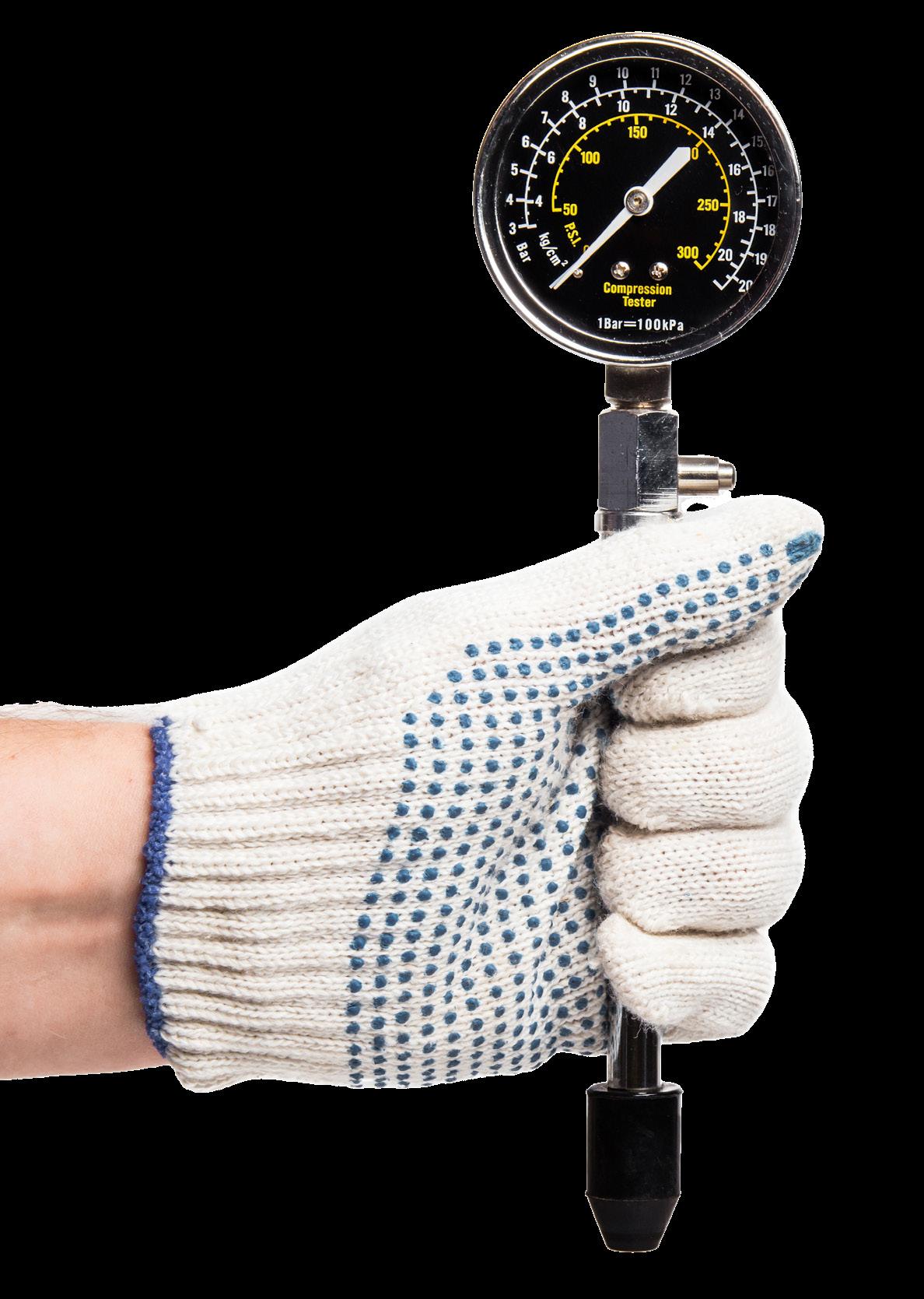
There are many types of compression-testing gauges that fit into the spark plug hole. Some have tapered tips, and others have threaded connectors. You will have to pick the right one for your application.
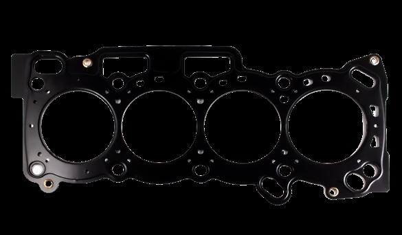
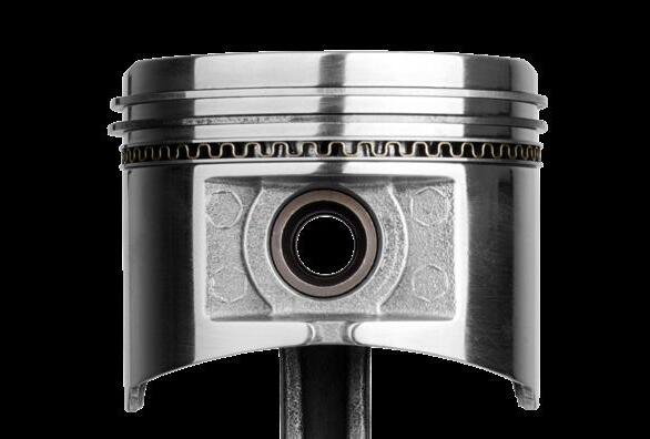
still seal against the cylinders, and the valves must seal to the head. If any of these leak, the compression stroke won’t properly squeeze the air/fuel mixture, reduce the engine’s power output or causing a cylinder miss when combustion doesn’t occur. See Diagram 3
Electric starter motors have been used for nearly as long to crank the engine over and get the four-stroke cycle pumping so the engine will start and keep going. So to complete a compression test, you would turn the key to start, or these days, press the start button while holding down the brake pedal, and the starter motor would engage.
But how do you crank a hybrid?
All of the above is ok with a conventional car, but what do you do with a hybrid drivetrain? There are many different types of hybrids, from 48V mild hybrids, which might still have a conventional starter motor, to high-voltage hybrids,
which may use the electric motor in the hybrid transmission to crank the engine. In some of these cases, the engine may not crank when the ignition is turned to start or when the start button is pressed, as cranking depends on engine temperature and the state of charge of the traction battery, among other factors.
Toyota and Lexus
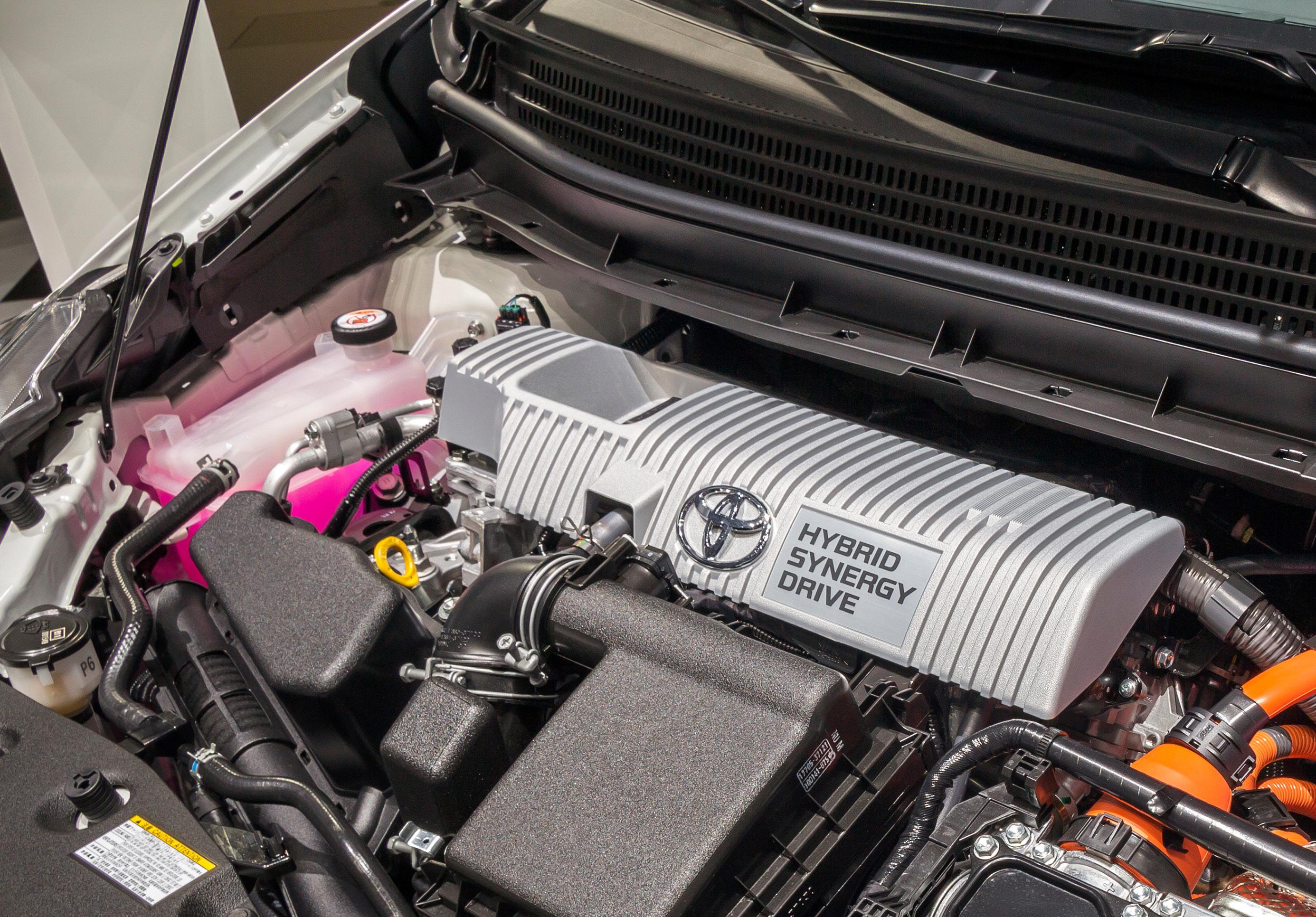
The Toyota and Lexus hybrid systems, which are very common on Australian roads, use their high-voltage motor generator (MG1), mounted between the engine and transmission, to crank the engine using power from the large traction battery. There is no conventional starter motor, and the vehicle’s 12-volt battery is used only to power the control units and doesn’t contribute to cranking the engine.
To conduct a compression test on one of these Toyota or Lexus hybrids, the following is an overview based on comparing the steps across a few models as they share similar procedures.
DIAGRAM 1
Compression testing
To check that the combustion chamber is sealing to an acceptable level, a compression test is required. The basic steps are as follows.
1. Ensure that the engine is at operating temperature.
2. Remove all of the spark plugs.
3. Disable the ignition and fuel delivery systems.
4. Insert your compression test tool. Some will have a threaded attachment, others will have a rubber taper, which you will have to hold in firmly. See Diagram 1
5. Hold the accelerator fully down. Many modern vehicles will go into “Clear Flood” mode when the throttle is held open and cranked; this will also disable the injectors in most cases.
6. Have the engine cranked over until the highest reading is recorded. In modern cars with pushbutton start, you will have to hold the brake pedal down, then press the start button to crank the engine. NOTE: Don’t crank for more than 30 seconds at a time, as you might overheat the starter.
7. Then complete the steps above on all cylinders so the readings can be compared.
As a rule, all compressions should be between 10 to 15% of each other. Refer to VACC MotorTech for the specification on compression pressures for a known-good engine of the type you are testing.
1. Connect a compatible diagnostic tool to set the vehicle to “Inspection Mode” or sometimes called “Maintenance Mode”. This will force the engine to start and idle, allowing it to reach operating temperature.
2. Then disconnect the wiring from the injectors, remove the coils, and remove the spark plugs.
The previous test will give you an overall engine condition and whether the compression is low, uneven or normal and is considered a Dry Test. If one or more cylinders have low compression, a wet compression test will narrow down the cause.
Wet compression test
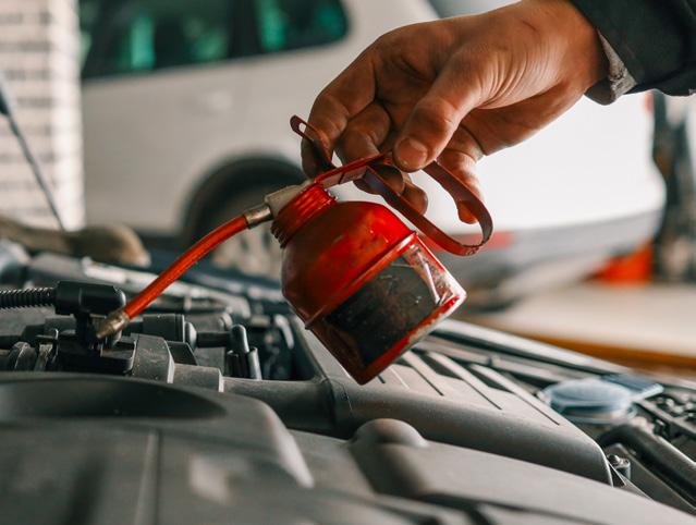
If you add a small amount of oil down the spark plug hole (5-10ml) of the cylinder with low compression, this will temporarily improve the piston rings seal to the cylinder wall. If another compression test shows a significant improvement (approximately 20% over the dry test), it can be assumed that worn piston rings are the problem. If the compression doesn’t improve, then it could be burnt or bent valves or a failed cylinder head gasket. If two cylinders have low compression next to each other, the cylinder head could have failed between these cylinders. Dry low + Wet high = piston rings/cylinder wear
Dry low + Wet unchanged = valves or head gasket
3. Turn on the ignition and, with the diagnostic tool, navigate to “Compress Test” via the following OE menu options (these may be different in aftermarket tools).
For a 2008 Prius Diagnosis>OBD/MOBD> HV ECU > Active Test > Compress Test
For a 2020 Hybrid RAV4
Powertrain > Hybrid Control > Active Test> Compression Test
4. Once engaged, with the brake pedal depressed, press the start button to crank the engine.
NOTE: Refer to VACC MotorTech for the manual procedures to enter “Inspection Mode” which will allow you to crank the engine without a diagnostic tool.
Other manufacturers
There are many different types of hybrid systems from a growing number of manufacturers that could have similar active tests via a diagnostic tool. Unfortunately, our research has shown that some workshop manuals for Chinese brands don’t give a procedure for a compression test, which seems like an oversight. One example we have found is in a 2024 Jaecoo J7 PHEV, which leaves some steps to the imagination
1. Turn the power state to “OFF” by swiping down on the central display and selecting “Power Off”.
2. Remove the ignition coils.
3. Remove the spark plugs.
4. Fit the compression gauge to the cylinder to be tested.
5. With the transmission in Park, depress the accelerator pedal fully.
6. Then crank the engine. There are no instructions for this, as this vehicle does not have a start button or key. One would assume that you would have to depress the brake pedal, but this is not stated.
7. Once you have made the engine crank for 3 to 5 seconds, you should have a reading on your compression gauge.
Relative compression testing
If you are looking for a quick way to check if all cylinders are producing a similar amount of compression, a relative compression test was once also quick and simple, but hybrids may have complicated this as well.
In a conventional internal combustion engine with a starter motor, if your workshop has an oscilloscope with an amp clamp, you could disable the engine and then engage the starter motor with the amp clamp around the negative battery cable. The oscilloscope pattern would show a rise and fall in current with each engine compression stroke, and if you add a second channel to the scope for the ignition signal for cylinder No 1, you could quickly identify which cylinder had a lower current bump by following the firing order.
See Diagram 5
This indicates that the cylinder has lower compression, as less current is required to turn the engine over on that one. There are also methods of checking the voltage pattern to produce a simllar pattern. With a hybrid engine without a conventional starter, there is no known or safe way of measuring the current while cranking. Some suggest that you can pick up the crank angle sensor signal, and
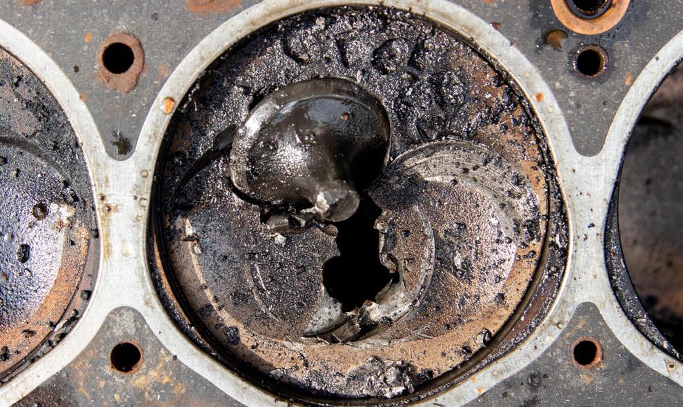
In this example, something has gone catastrophically wrong with the cam timing, or the valve has dropped out of the head and smashed a hole in the piston. The wet test will not show any differences in this case.
with the correct maths channel, you can interpret the output as a relative compression test. But this is beyond the scope of this article. Some OE and aftermarket diagnostic tools may offer a relative compression test, which is convenient. You should remember that a relative compression test should be used as a guide only. If all actual compression pressures are low, this test will not show
DIAGRAM 3 Areas where compression can escape
DIAGRAM 4 When things go horribly wrong
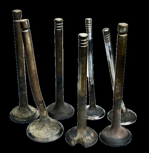
Burned and bent valves
A failed head gasket can allow compression gases into the coolant passages or adjacent cylinders.
Failed piston rings allow compression gases into the crankcase, causing excessive blow-by.
any problem, but it is very useful for identifying problems with individual cylinders or between banks (e.g., cam timing issues).
Conclusion
Conducting a compression test with an accurate gauge is a great way to assess the engine’s condition and identify mechanical wear and damage in one or more cylinders. Once you have confirmed that the compression is within specification, you can confidently move on to other areas if you are looking for performance issues or engine misfires. This article is an overview and should only be used as a guide. However, a compression test on a hybrid vehicle can be performed with the appropriate equipment
DIAGRAM 5 Relative compression test wave pattern
With an oscilloscope and an amp clamp over the negative battery cable on the 12-volt battery, you can see the rise and fall of each compression stroke. This example is a 4-cylinder engine with No.1 cylinder ignition pattern showing. The wave of No 1 cylinder is lower than the others, indicating that the compression could be low for this cylinder relative to the others.